


Design
Test Track Construction I - Plan to Roadbed
26 August 2017 22:14
After entirely too long dithering about, it’s time to actually lay some track. Or at least, begin the process.
As I mentioned in my earlier post on Planning a Test Track, this is going to replicate the crossovers west of Ochanomizu Station, which will allow me to test prototypical signaling, as well as operation of trans through some complex crossovers on my planned code 55 rail. If I’m going to have problems with that, this is where I want to discover it.
First, I made some basic tests, running cars by hand on Micro Engineering Code 55 flex track, both with wood and concrete ties. This was just to determine if typical wheels would have problems with the low profile (e.g., bumping into moulded-on spikes, etc). I tested with Kato, Tomix and Micro Ace models, both passenger and freight, and all worked flawlessly. These were all of relatively recent manufacture, but it suggests that I’ll be able to use code 55 rail without problems.
My fallback plan was to switch to code 70 track if this didn’t work, and that still might happen if problems turn up on the test track. But I’d really prefer to have the lower-profile rail if possible.
Designing the Track Plan
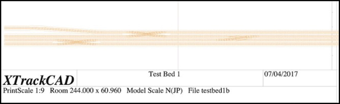
I laid out a track plan eight feet (244 cm) in length, to fit my pair of four-foot long boards. A print of this is shown at the top of the post. For this I just included two #8 double crossovers and a single crossover, the latter made from facing #8 switches. I also tried my hand at widening the inter-track spacing of one line, mostly to see how well i could do this in XTrackCAD (see my XTrackCAD page for details), but it would also provide a test of car behavior on an S-curve (I put a 20 cm straight section between the two curves).
This is slightly compressed from the prototype. The actual distance from the bridge at the end of Ochanomizu station where the half-crossover is located to the second double crossover is about 550 meters, or nearly long enough for three ten-car trains (each of which are about 200 m in length). The total distance on my test board is eight feet, which in 1:150 (Japanese N Scale) equates to about 366 scale meters, slightly shorter than two “200 m” model trains (which are about 4’ 5” each), and the crossings are even closer to each other.
One goal of my modeling is to make the space between stations large enough that a train seems to spend time traveling from one to another. On the original Sumida Crossing my two stations were about 2.5 m (7.5 feet) apart, but that was with a curve, which made the space look even longer. So another purpose of this track is to let me see how models will look on such a replica of prototype track if I do a “scene” of the interlocking between the two stations as a mostly-straight track.
I left a roughly 6” (150 mm) margin on the “front” of the board, and most of the back half is empty. This will provide mounting space for electronics and circuit prototyping boards (where I’ll put LEDs and resistors to fill in for signals). I was also careful not to place any of the switches near the edge of one of the physical boards, so that I could have removable track across the gap of sufficient length to adjust for any minor alignment problems.
Most of the track plan creation followed the same basic process I described in my Learning XTrackCAD post last year, but the S-curve was new. As described on my XTrackCAD page I created this using two eased curves over a total length of about 50 cm, creating a smoothly flowing widening of the inter-track spacing. This looks good, and the numbers seem to be right, but I’m going to have to build it and run some trains through it to be sure it works as well as I expect it to.
One potential construction problem I have is that the 28 mm center-to-center track spacing I’m using is less than the 31 mm width of the base of the Woodland Scenics foam roadbed I plan to use, which will mean I need to trim each piece when creating paired tracks, which will be most of my track. The result is likely to be less than perfect, but I should be able to hide that under ballast, and the outer edges can remain untrimmed.
As I’ve mentioned before, the 28 mm spacing is enforced by the double-crossover jig I’m using (hand-laid tracks, #8 double-crossover). This differs slightly from the 26 mm spacing I’d originally planned to use (NMRA standard straight-track spacing equates to 26.2 mm). For prototype Japanese commuter lines, the minimum legal spacing equates to just over 24 mm (see my Track Standards for Straight Track page for much more detail) and I found spacings much wider than 26 mm looked “unrealistic” to my eye. So 28 mm is not ideal, and I may use closer spacing on the final layout, away from crossovers, which aren’t all that common on most lines.
Transferring the Plan
Having drawn the plan, I then printed it out in 1:1 scale. Doing this was yet another learning experience (the online instructions skip over some of the important details). First, I used page setup in XTrackCAD to select landscape mode, since my layout was long and narrow. I also selected “any printer” and “US Letter” paper, since that’s what I’m using.
Then in the XTrackCAD print dialog, I selected a “Print Scale” of 1, meaning full-size, and set the width of the roadbed outline to 3.100 (it is in cm, as are nearly all metric measurements in XTC). In addition to checking “Print Roadbed” and leaving “Print Rulers” checked (it was on by default), I also checked “Ignore Page Margins”, “Print Registration Marks”, and unchecked “Engineering Data” (which meant I didn’t get page numbers, but I’m aligning these based on the rulers).
The registration marks are important, as you can measure spacing between them and check alignment over longer distances using a yardstick or long board, to make sure minor errors don’t slip in when you place the paper on the layout.
The thing it took me some time to figure out is that you have to “select” areas to be printed by clicking on the main XTrackCAD window after you have the print dialog open. This is useful since you don’t have to print everything, but it is very badly documented and without doing it the “Print” button is grayed out and won’t work.
I then clicked “Print”, which brought up a second window where I could select the printer. Here I selected “Print to File” and PDF format, and “all pages”, which gave me a PDF with all of the layout I’d selected.
Now at this point, things will vary by operating system. I’m on a Mac, so I used Preview to open the PDF and clicked Print, which gives me my Operating System’s print dialog. Here I changed from “Scale to Fit” (the default) to “Scale” and “100%” (the default for the printer I was using was 97%, which would have distorted the measurements). Here you can choose to print subsets of the pages, in case you have a problem and need to reprint one, or are only working on part of the construction at a time.
I did find that some of the track near the edge of the paper didn’t print in this mode. The benefit is that “Ignore Page Margins” means that you can line up the paper edge to edge and the registration marks will be the correct distance apart, which simplifies laying the paper out on the baseboard.
I then trimmed the printed paper so that only the track outline plus some extra bits for the registration marks every 10 cm remained. Holes were punched along the centerline, and then the paper was laid on the boards. Once I was sure it was all correct, a Sharpie was used to trace the edges of the roadbed and the track centers.
Next up: I need to start laying track.
Planning a Test Track
20 May 2017 00:31
I’ve been thinking about this for about two years now, but it’s finally made it to the head of my “things to do” list: I want to build a short test track using the techniques I plan to use for the new layout: code 55 flex track and turnouts made using the Fast Tracks soldering jigs.
There are several reasons for this: first, I want to refresh my flex-track skills. Second, I want to learn how to use the jigs to make turnouts. Third, I want a fairly complex interlocking where I can try out electronics for detecting trains and controlling signals and interlocking those with turnouts, as well as interfacing all of that to DCC and JMRI running on a computer. And finally, I need to test some trains and see if they have any issues with this type of track.
So the first order of business was to figure out what I want the interlocking to look like. I started by sketching out an interlocking with a couple of tracks and some sidings, which was a nice, generic, interlocking, but not really representative of what I want to model. I’m modeling high-density urban commuter passenger lines in Tōkyō, and those are double-track with few sidings.
So that turned my thoughts to the junction between the Chūō Line and Sōbu Line at Ochanomizu Station, and the set of interlockings just to the west of there, between Ochanomizu and Suidōbashi stations. I’ve done a lot of research on that area, and know the layout of the track and associated signals fairly well. It has a mix of 3, 4 and 5-lamp signal heads, so I can test most and maybe all of the signal types I’d use. Plus it’s a very complex environment, which makes for a good test.
Read More...
Learning XTrackCAD
18 June 2016 23:32
Today's post is about my latest (and more successful) attempt to learn to use XTrackCAD for layout design (see diagram above). I've made a few half-hearted attempts in the past, but was always turned off by the amount of up-front work needed to learn the dang thing. It's not at all obvious, at least not to me. This time I started knowing it was going to be a pain, but with the commitment to see that through.
Much of what I learned was basic, but some of it was very specific to what I'm doing, which is a flex track layout in Japanese N scale. If you weren't already aware, Japanese N is 1:150 scale rather than the usual 1:160 used in American/European N, and, oddly, for Japanese Shinkansen models, but I'm modeling normal trains for the most part. And I'm also planning to hand-lay at least some turnouts using the Fast Tracks jigs, although that turned out to be a lot simpler to design in XTrackCAD than I'd expected.
Read More...
Ochanomizu Station Signals
03 April 2016 23:28
JR’s Ochanomizu Station (御茶ノ水駅, Ochanomizu-eki) is an important part of my modeling plans. As seen in the photo above, it’s a mix of old and new architecture. And it’s built along the bank of the Kanda river (the temporary construction platform on the right is actually erected over the river). It’s slightly below street level, with a city skyline climbing up behind it from a front rank of buildings around six stories in height to taller ones further away. It’s pretty much ideal as a modeling subject visually, and it sits at the junction of two busy lines, so there is a lot of activity.
I have been trying to figure out how the signals here and nearby work so that I can include a reasonable subset in my model, but photos in and around the station tend to focus on other subjects than signals for some reason. Thanks to one of my readers, George Roberts, I now have a number of photographs taken around the station and adjacent areas that include these signals (and other interesting details).
Read More...
Modeling Prototype Signaling I
15 March 2016 23:24
Today's post follows my earlier series on prototype signaling (Part I: Development and Part II: Blocks), but it's about how to capture a specific prototype environment on a model railroad. For example purposes, I'm going to look at a real-world location I plan to model, Ochanomizu station and the crossovers just west of it. This is a fairly complex case, as it involves a junction of two double-track lines. On the other hand, it's a relatively simple station without multiple platforms per track, which simplifies things a bit.
The question at hand is: how would I replicate somewhat realistic prototype signals for this location? It's an important question, as I'll eventually need to do it. And determining the right answer is a good way to clarify my understanding of the topic, so I can create similar solutions for other locations on the layout. I may or may not actually do it this way when the time comes, but working through this example now helps clarify my thinking.
But I’ll get into the detail of that in another post. For now I’m going to focus on the signals and related systems around a simple crossover (above) so that I can introduce the various pieces that make up the whole, and explain how they fit together.
I started by studying everything I could find about the real signals at this location, which I wrote up as part of my post about this line. Mostly that involved looking at photographs, although before that I'd studied the MLIT document (PDF) that defines how Japanese railroads are supposed to use signals, as well as checking Wikipedia and other sources. I cover all of that in my prototype Signals pages.
Read More...
Scene Planning - Chūō Along the Kanda
15 February 2016 22:51
My next layout is still very much in the back-of-a-napkin planning stage. I’m thinking about what goes into it more than the details of how I realize that. I have several things I know I want: multi-track urban commuter railroading, “layered” scenery with water, roads and railroads crossing each other at different levels, and prototype scenes from the core of Tōkyō. But just exactly what that means hasn’t fully come together yet.
One thing I do know that I want is a riverside scene or scenes along the Kanda river. This is a small river, running east to west and ending at its intersection with the much larger Sumida river in the center of the city. Near the eastern end it passes just south of the famous Akihabara district. A four-track mainline runs west along its south bank for a mile or so (about 2 km) before turning southwest along a different waterway and ultimately disappearing into a tunnel and turning north into Shinjuku station.
The railway along these two waterways lies in the center of Tōkyō, between the eastern and wester sides of the Yamanote line loop, which passes through Tōkyō station on the eastern end and Shinjuku station on the western end, and it serves as a shortcut across the middle of that line. Originally this was part of the Kōbu Railway, built in the late 1890’s, although portions were completed shortly after nationalization of the railways occurred in 1906. This can be seen in the largely wooden construction of the stations, with complex riveted girderwork in places.
Read More...
New Plans for a New Year
01 January 2016 01:06
I'm going to usher in the new year with a new project, and try to get back to doing more frequent but smaller posts than I've done of late. I'm not quite back to railroading yet, although this is ultimately in support of that. But for the moment, I'm still playing with microelectronics. And today's post is just a summary of where I'm going and what I've done so far, which doesn't amount to much when you put it down in words.
I'm still thinking about and planning the next layout. Control systems are a big part of that, because I was never happy with the DCC-throttle control of turnouts I used on Sumida Crossing, and my attempt at a single big computer-driven system never got off the ground, and would have had some of the same issues if it did.
As you may have noticed, I've spent a lot of time looking at control bus systems over the last two years. I'm still on the fence about what to use, as I don't particularly like any of the current systems. LCC has promise, but so far that's all it has, and I'm not expecting much from it in the next couple of years; it's too new.
Read More...
Track, Turnouts and Servos
19 April 2015 22:46
If you follow the RSS feed on the main page, you can see that my interest in signals continues. However today’s topic is about what signals describe: track, and in particular the turnouts, or track switches, or just switches, used to direct the motion of trains, although I do mention the relation to signals briefly. And yes, it’s finally a post about the layout, even if it is about the as-yet unbuilt future layout.
I’ve been spending some time thinking about how I’ll do turnouts on the new layout. As part of my overall design, I’m planning to use code 55 rail on a mixture of concrete and wooden tie track (I’m undecided between PECO and Micro Engineering). And I may custom-build some track to replicate slab-type track, which is used by both Shinkansen (sometimes) and in some newer construction for narrow-gauge track, particularly in stations and on viaduct. Although I dislike unnecessary work (and hand-laid track is, to me, generally more effort than it’s worth), I do plan to put substantial effort into getting the track to both operate reliably and look as prototypical as I can. And thus hand-laying some portion of it for appearance purposes may be worth the effort.
Note: some Japanese models have issues with code 55 track due to larger-than-spec wheel flanges, and I’ll need to do some testing. But most of my models are Kato, and they generally use low-profile flanges that should work.
I’m also planning for very wide radius curves, although I have not yet picked a specific standard or minimum radius. I want both Shinkansen and commuter stock to look good on curves, with minimal overhang. That means I need much wider curves than the minimum operating radius. I may skimp a bit for storage and yard tracks, including modeled layover terminals where trains are kept off-peak. But mostly I’m considering track radii in the 30” or larger (750 mm or larger) range. And that raises the related question: what type of switches do I want to use?
Read More...
Signals and Signaling with Arduino
28 March 2015 22:28
I’m going to vary from my normal focus on modeling Japanese railroads today to talk about signals and modeling them in a more general sense. Heck, who am I kidding, there haven’t been many posts on modeling Japanese railroads of late. But I digress from my digression. Back to the subject: signals.
If you want to cut to the chase: I’ve written an Arduino library for controlling lineside LED-based signals. It’s only part of a complete signaling system that I’m working on, and at present you’d have to do more work to make practical use of it. But the code is public and can be used independently of anything else I’m eventually going to create; skip down to the end for details.
Read More...
More on Layout Lighting
07 September 2014 23:03
I’ve been thinking about a number of things related to the layout this month, but mostly about lighting the layout itself. The current layout is lit by a mix of my original track lighting system (using compact fluorescent bulbs) and the newer fluorescent tube valences.
That experience convinced me of the merits of fluorescent tube lighting. It also convinced me of the need to build the lighting valence as part of the benchwork, rather than trying to suspend it from an irregular ceiling. As you can see above, the heating ducts caused some difficulty in attaching the lighting units in this part of the basement.
Read More...
Transition Curves and Superelevation
04 August 2014 00:18
All of my Japanese-themed layouts to date have used sectional track, either Kato Unitrack or Tomix Finetrack. I haven’t built a layout using flex track in more than twenty years. And that layout was a relatively simple one, modeling an American freight shortline, with low-speed trains and no “mainline” trackage. That let me cut a few corners.
But now that I’m thinking of building a new layout using flex track, and particularly one with mainline track for both moderate-speed commuter and high-speed Shinkansen, it’s time for me to confront two of the more complicated aspects of trackwork that I’ve so far been able to avoid: transition curves and superelevation (for more information on these, see my Easements page). And it turns out, neither is really complicated after all.
Read More...
Going Around the Wall
05 July 2014 23:41
Benchwork is fundamental to a model railroad. It provides the structure that ties everything together, and over the long term dictates what can and cannot be done. While I created Sumida Crossing, I was intent on recreating the “tabletop” approach I’d used on the Kitchen Table Layout, but as a sectional layout with permanent scenery, something that would hold up well to moves.
That led to a number of decisions on how to build my benchwork. But now that I’m thinking of a different kind of layout, I need to re-think that, examine my past decisions, and decide on a new structure. Read on for the details.
Read More...
That led to a number of decisions on how to build my benchwork. But now that I’m thinking of a different kind of layout, I need to re-think that, examine my past decisions, and decide on a new structure. Read on for the details.
Read More...
Rethinking Sumida Crossing
28 June 2014 23:22
Well, that was a long break. Two months without a post. No, it wasn’t anything serious. In part, just life getting in the way of this hobby, but more a realization that I’d lost my motivation somewhere. Not really intentionally, I took a break to clear my head.
It was really longer than two months. In March of 2011, about 40 months ago, I took apart the wiring for the functioning DC-powered Sumida Crossing and began the conversion to DCC. The railroad had been designed for this. It should have been simple. It turned into a nightmare. I distracted myself by focusing on other (important) aspects of the layout, and kept the two outer tracks live as switchable DC/DCC, but without all the bells and whistles of DCC I’d planned, so I could continue to run trains. And for a time I kept working on the conversion, but less and less got done there.
Last year I set out to make a short tram layout, something I’m still interested in, but that was really a distraction, and my latent unhappiness with the main layout colored that work. As did my tendency to perfectionism; I kept not doing things while I tried to work out the One True Way to do them, and that never works. After a burst of activity in April, that all came to a halt.
Read More...
Occupancy Detection Yet Again
23 October 2013 00:49
About fifteen months ago work on adding occupancy detection to Sumida Crossing stalled. That was in part because I’d planned to use the BDL168 detectors to also do transponding, and a few months earlier had abandoned that plan since I was unable to get that aspect to work reliably, even on a simple test track. The number of solder joints on the BDL was also a nuisance that caused me to put off further work.
Recently I’ve been rethinking my approach. The BDL168 is an amazingly cost-effective solution. Ignoring the transponding part, you get 16 detectors on a board that includes a LocoNet bus interface for US$120 (street price). That’s $7.50 per detector (if you can use all 16). That’s really hard to beat for a bus-connected detector. I’d originally planned to install one per table on the layout, and my cost would have worked out to around $10 to $15 per detector on average.
On the other hand, I’m thinking that I might want to move to either a OpenLCB/NMRAnet bus (if I want a feature-rich bus for the future) or a really dumb serial bus (like S88 or C/MRI). The latter is attractive since I can potentially interface to it with an Arduino, opening up some room for home-brew devices. Of course I could do that with NMRAnet, but today that requires a US$45 shield to add to the Arduino (or one with it built in), which kind of takes away from the appeal of using $10 Arduinos to do things like drive signal masts.
While thinking about this, I went off and started researching what was available commercially or as home-brew circuitry and software libraries for these busses and for doing occupancy detection with them, as the latter would be a good way to get my feet wet and solve my “don’t want to solder those #$@! BDL168s any more” problem.
But in the past week I’ve been sidetracked into looking at homebrew inductive-coil detection circuits.
Read More...
Central Station I - Design
05 October 2013 23:39
After initially thinking I’d build my own viaduct for the One Point Five Meter Line’s urban station, I’ve decided instead to use Kato’s Viaduct Station Entrance building (I had a spare one), possibly supplemented by one of the Station Shops buildings, as seen above. This will be fine even though I’m using Tomix track and station platforms, since the viaduct station simply creates a flat base for track, and isn’t specific to Kato’s track. The height would be, but I’m not connecting it to Tomix viaduct track, so that doesn’t matter.
Read More...
Read More...
Arduino Signals II - Video and Flickering
29 September 2013 00:25
I’ve continued working on the code to drive LED signals with an Arduino. I’d previously discussed my approach, and provided the code I was using at that time. I’ve learned a bit since then, and cleaned up the code significantly. I’ll provide a link to the current example program at the end of this post.
Fundamentally nothing has changed. I’m still planning to use NJI common-anode SMD LED signals (in fact, I’ve ordered them). What I did do was change the code so that a “bank” of two signals would always have both lit (meaning two of the four LEDs would be on when the bank was active) so that I could get through the full set of signals more quickly. One reason for this has to do with video camera shutter speeds. I think it’s worth saying a bit about that issue.
I’ve also made some changes to make the time wasted in turning the pins on and off less, since at these speeds that is becoming a significant percentage of the total LED cycle, and I need that time for the eventual Tram Controller program to be doing other things. These changes consisted of adding a library that provides faster versions of writeDigital and pinMode, as well as keeping track of what state pins are on, and not trying to change them unless the new state differs (this got rid of a number of “change disabled pin X to disabled” changes).
In my test program, when cycling at 8 milliseconds, I’m now spending just a quarter millisecond changing those pins with three banks (6 signals) in use. My One Point Five Meter line will only use four signals, as it doesn’t have the extended double-track section of the full Tram Line, which needs six. And so it will run even more efficiently. Read More...
August 2013 Status - a Retrospective
03 September 2013 23:49
And not only another month, but another year has passed. Not much happened in August; as I mentioned last time I’ve mostly been working on the Arduino project. So this month’s post will focus on the past, but will also look forward to the future.
This month marks the fourth anniversary of Sumida Crossing, dating things from the start of construction. Planning actually started earlier, around June of 2009 in earnest although there had been a lot of thought prior to that. And the first real train didn’t run until early 2010 (unless you count a test on a loop of temporary track). And actually, although the first post in this blog dates from September 16, it wasn’t actually online until the end of November. Prior to that I’d been working on the initial version of the website offline, and hadn’t bought the domain name or space on a server until I judged it ready. I don’t think it even had a name before November; I’m pretty sure I made that up when I bought the domain name.
Read More...
Tram Controller Status
31 August 2013 22:47
I’m continuing to work on the Tram Controller project (main page, past musings), to the exclusion of all else layout-related, which doesn’t make for interesting posts here. But I’ve made a number of decisions in the past month, and it’s probably worth summarizing them and where that puts the project overall. Short answer: making good progress, but slower than anticipated (what else is new; all my projects run “slower than anticipated”).
I’ve also been thinking about the diorama-like layout I’m going to initially use this with. The current candidate plans for that are on the new One Point Five Meter Line page.
Read More...
I’ve also been thinking about the diorama-like layout I’m going to initially use this with. The current candidate plans for that are on the new One Point Five Meter Line page.
Read More...
Signaling with Arduino
19 August 2013 23:43
t seems that I can never resist the impulse to make things more complicated. While working on my Arduino sketch (program) for the Tram Controller, the thought struck me that I could add signals at the stations to tell the fictive operators of the trams when it was safe to leave. These would be “starting signals” in typical Japanese practice, and only require two LEDs, red and green. Of course I’m all out of pins, and the only step up from the Uno, which has 20 pins (14 digital, 6 analog) is the Mega with a whopping 70 pins (54 digital, 16 analog).
Read More...
Read More...
One Point Five Meters
12 August 2013 23:04
One point five meters, or about five feet. That’s how much space I’m giving myself for a short layout designed to display my buildings separate from the main layout. It’s also going to give me a short rail line that I can use with the controller I’m working on for the tram line on the Urban Station scene.
The germ of this idea was a conversation at a local hobby store that holds an annual show in the store to display the model-building skills of its customers. Last month, just before the show, I was asked about some of the pre-built buildings I’ve been detailing for my Village scene. At the time, I didn’t think the couple I’d mostly finished were really in a displayable state, but the idea of perhaps doing some kind of diorama crossed my mind as we discussed how to display something next year.
I also wanted some way to actually see the tram line in operation, as on the layout it’s going to be hidden away behind buildings, providing some background activity without really being visible (something I really need to fix on a future layout). And that led me to think: how small can I make a layout with the tram controller and my buildings?
Read More...
Mocking Up the Hilltop
15 July 2013 01:15
It’s very pink, but with a bit of imagination you can see the forested hill rising behind the houses, which will have a small Shinto shrine tucked in amongst the trees, with a stairway down to street level, a very typically Japanese scene. This mock-up was part of my final refinement of the design for the Hilltop Scene. I’m not quite done, but I’m beginning to accept that I have a sound idea for what I want to do.
Read More...
Read More...
A Small Parking Garage
12 July 2013 00:17
Many people who live in cities, even cities with much poorer public transportation than Tōkyō, can get by without an automobile, and do. Access to work, shopping, and social activities is often possible on foot or via what public transportation exists. Or other methods of transport, like bicycles, may be sufficient. But while that is true, many people who live in cities, particularly large, sprawling cities, do choose to own cars, and Tōkyō is no exception.
People can live a long distance from work, or may simply want a car for weekend use or to visit distant friends or relatives, particularly if they need to travel to rural areas where public transportation is less prevalent. Whatever the reason, many people have cars. And in Tōkyō, you can’t own a car unless you can prove you have a place to park it. Street parking is relatively uncommon.
Much of the city is comprised of small apartment buildings, and even houses. Houses may have a small space inside the property line to park a car, not so much a driveway as a paved front yard. But apartment dwellers need something else, and small parking lots or garages are fairly common. Read More...
Village Construction
02 July 2013 11:09
The title might be a bit overdone, but I’ve moved from the “thinking about it” stage to the “building mockups” stage. It’s still planing of a sort, but it feels more like construction. I was ready to start cutting styrene a couple of days ago, but now I think I need a little more contemplation and review before I do that.
I’ve also started taking apart the buildings to prep them for painting, although I’ve realized that I need to adjust my positions slightly, which has diverted my attention from that work. I’ve also started working on my detailed design for the roads and intersection, which is partly what’s caused that re-think about posiitoning.
After more research on road sizes, summarized on the Roads and Highways prototype page, and a good deal of thought about the actual size of my roads, summarized on my Cars and Roads modeling page, I started drawing a 1:1 scale graphic of the road in my layered drawing program (Omnigraffle). My hope is to replace some of the layers with photographs of concrete, asphalt, and similar, as well as adding in details like manhole covers, and then print the final version as either a decal or photo that would be layered onto styrene. Using styrene as a backing has one benefit for use of a decal: printers can’t print white, so decals leave that color clear. A decal applied to white-painted styrene will look correct even if it contains white lines. I may use a similar technique to create the sidewalk as a separate item, although I’m also considering just using painted “tile” sheet styrene and applying separate delays for things like manholes and “braille” safety strips at crosswalks. Read More...
Planning the Village II
23 June 2013 22:50
Eighteen months on from the first post on this topic, and the scenery in my Village area hasn’t really progressed, but I’ve turned my attention back to it, and am close to having a final layout of buildings. I think. From here, things should start to move. The overall design hasn’t changed: still a broad avenue with commercial buildings up the middle, two typically-narrow side streets, with businesses mixed with residences on one side. The exact selection of buildings, and their placement, has evolved though.
To get here, I finally mapped out the ground I had to work with and put that into a drawing program, then I created outlines of the footprints of each of my candidate buildings, and set to work trying different arrangements by dragging the outlines around on a second layer above the drawing. Layered object drawing programs are so useful for exercises like this; I used Omnigraffle on the Mac, but anything with basic shapes and layers should work similarly.
Along the way I finally decided that the Tomix gas station, as much as I liked the model, really wasn’t going to fit. I’d somewhat realized that last year, which is one reason work on that structure had halted last summer. I may reuse parts of it, although I anticipate scratchbuilding most of the new gas station, which will be sized to fit a spare corner. I also had to abandon plans to use one of the more traditional brown wooden residence/business buildings made by Kato, as they just didn’t fit anywhere.
I also decided, based on purusing Google Earth views of the banks of the lower Sumida River, that some of the oddly-shaped corners could be used as small parks with trees, and perhaps recreational equipment for children, as that’s how such gaps are used in the real world.
Read More...
Arduino Controls and a Simple Throttle
14 May 2013 23:03
Having covered the motor control and the sensors, my next step in creating the automated two tram controller was to deal with the very small number of controls I need to have. In my original design, the plan was to have just three pushbuttons:
- Run: when pressed, the trains would start to move.
- Park: when pressed, the trains would return to their starting locations so the system could be turned off.
- Emergency Stop: when pressed, the trains would come to an immediate stop until run was pressed again.
And all three were to be “on when pressed, off when released” pushbutton switches. I was already thinking this needed to be changed, and when I started playing with switches I became even more convinced.
There are two benefits to using toggles versus “on while held” button switches: first, I eliminate a switch, since I need two toggles rather than three pushbuttons. Second, I avoid using those pushbuttons, which have proven to be problematic in my testing. They tend to “bounce” for a long time, and they may remain “on” only for a fairly brief time, making it hard to avoid all bounces and still reliably tell that they were pressed in the first place.
The other control I wanted to add was a way to customize the top speed of a train (or trains, really), so the different models could be made to run at similar (and prototypical) speeds. I don’t want one train rocketing down the tracks while the other creeps along, even if they have very different motors and gear-trains. So I’m going to add a pair of potentiometers, used as “tram #1 max speed” and “tram #2 max speed” controls. And note that these are for the trains, not the motor shield A/B outputs. At various times each tram will be controlled by one or the other.
My first step was to create a simple throttle that used one pot, three switches, and one motor control to run a train on a simple test track. This gives me a proof-of-concept example that ensures I really understand what I think I understand (always a concern with me and electronics).
Read More...
Detecting Trains with IR Sensors, Part II
04 May 2013 00:11
This is going to be a short post: it’s working! I have my IR LED phototransistor sensor program detecting things (not trains just yet), and I’ve posted the example code, see the bottom of the Tram Controller page for a links to that, and the earlier motor control code. Both example programs are public domain, feel free to use them however you see fit. I’ve benefited from a lot of public domain programs, and I think it’s only fair to give something back. When the tram controller program is a bit more polished, I plan to publish it in the same way, although it may be months before I get to that point.
Read More...
Read More...
Detecting Trains with IR Sensors, Part I
30 April 2013 01:02
In my continuing work on the Arduino-based Tram Controller, I’m now playing around with the part I really wanted to work with, the Infra-red optical sensors themselves. This turned out to be rather more complex than I’d anticipated, but I’m most of the way there, even if I don’t quite have the system working yet. This is a post about what I’ve done so far, and what I’ve learned, with a bit about what remains to be done.
Read More...
Read More...
Arduino CPUs and Motor Shields
21 April 2013 22:08
I’m still playing with Arduinos this week, but the little beasties are multiplying. That’s partly because I want to be able to test with the various CPU architectures, but also because each has unique strengths and weaknesses, and I’m still evaluating which of them is going to be the right choice for my tram controller. At the same time, it turns out that there are a number of options for motor shields, as I mentioned last time, and they too have strengths and weaknesses.
Read More...
Read More...
Modeling Subways
29 March 2013 02:55
I realized that my subway material was scattered over several pages, and I didn’t really have anything that tied them all together. Also, some of the pages were a bit out of date. The main page is the Subway Line page. I’ve updated the outdated material, and here’s a post to describe what I was trying to do, how I went about it, and what I’d do differently next time. I’ll link to other pages in the text below.
A subway isn’t something you find on a lot of model railroads, but then most model railroads are focused on freight operations. Even ordinary railroads back in the steam era had underground stations (New York’s Grand Central Terminal has 44 platforms, all underground). Property costs in modern cities make it even more likely for structures to be built above the tracks, partially or wholly covering the station. Boston’s Back Bay station used to be above ground, largely in a cutting, but today is mostly out of sight below ground except for the entrance building and ventilation stacks.
Despite the high property values in Tōkyō today, most of the stations are surprisingly at or above ground level. In part that’s because the rail lines’ growth came after dense urbanization, so elevated lines were a more practical solution for expanding them. The city does have subways, and most of them use the same gauge track and same voltage power supply as the above-ground commuter lines, so some of these subways provide access to the city center for suburban commuter trains. Several subway lines have underground stations below or near surface line stations, to allow transfers.
I’ve used that as an important aspect of my modeling to capture the “layered” feel of urban railroading. Cities rarely exist on a single level, even ignoring multi-story buildings. There are often below-ground open plazas and hidden shopping arcades, and highways and rail lines exist and cross on multiple levels. Cities aren’t flat, and models of cities shouldn’t be flat either.
Read More...
Computer Support
13 February 2013 23:28
A computer is part of my model railroad. Why, and how do I use it? Well, the answer to the last question is “not very much”, so far, but I have plans. I recently had to re-do the monitor support attached to the layout, and I thought I’d discuss the reason it’s there, as well as the work on the support itself.
Read More...
Read More...
Rethinking Storage Tracks and January 2013 Status
31 January 2013 23:25
While I’m spending a lot of time playing with decoders, that’s not the only thing on my mind. One idea that’s been eating at me for a while now is to redesign the under-table storage tracks. I’d originally planned to locate these under the Urban Station scene, reached by a helix that led down to them from the “unsceniced” end.
On reflection, this was less than ideal. First, any access to the underside of the layout for wiring work would require removing all of the trains from storage. Second, the helix to reach them would be quite long, at five and a half turns, which would be expensive and overly complex. Third, if I needed to work on the trains, I’d be kneeling on the concrete floor and reaching into a narrow space to access the trains on the back track, which pretty much guaranteed I wouldn’t be able to do much. The only thing it had going for it was that I could store a full-length sixteen-car Shinkansen (2.5m or eight and a half feet long) down there.
Read More...
Configuring The EM13 Part I
13 January 2013 02:32
Kato’s EM13 DCC decoder (29-351) is a specialized decoder used for the motor car in an EMU/DMU model or other “DCC Friendly” models made by Kato. DCC Friendly (the English term is used even in Japanese, rendered as “DCCフレンドリー” or “DCC furendorī”) isn’t the same as “DCC Ready”, and it is a phrase used by others to simply mean that a model is relatively easy to convert to DCC. But when Kato uses it, the phrase means “will accept Kato FR11, FL12 and/or EM13 decoders”. And the models that do so are primarily Kato’s N-scale Japanese prototype models: commuter trains, limited express trains and Shinkansen (bullet trains). They also use it in some steam locomotive models, including the American-prototype GS-4.
Read More...
Read More...
DCC Voltage and Cab Lights
23 December 2012 01:58
’m turning my attention to the cab car decoder install now, and a recent discussion with Don along with a question from a reader had me thinking about potential problems with DCC conversion of N-scale EMU cars with cab lighting. And the one that really worried me was overvoltage from high DCC track voltages, and its harmful (fatal) effect on LEDs. DCC decoders essentially pass track voltage (minus a small bit) through to their function outputs.
Read More...
Read More...
Wire
16 December 2012 02:55
I went off on a tangent this past week. It all started when I asked myself: what gauge wire should I use on my decoders? And the root of that question was thinking that the wire I’d used on my first install, two weeks ago, was too thick. The answer turned out to be less obvious than I thought it would be, and consumed (and is still consuming; I’m not done) a lot of time.
Read More...
Read More...
Getting Organized
23 September 2012 22:51
I’m not a very organized person. That may sound odd, given that this “blog” has a fairly extensive set of associated pages that are moderately well organized. But while I’m at least competent at organizing information, that skill doesn’t extend to the real world much at all.
When I started building the layout, I only had a few trains. Over the next two years I bought quite a few more, and partway through that the one shelf I had set aside for storing them became full and I expanded to half of a second. That filled, and there were no more available. Green Kato boxes began getting stacked in odd corners, on the layout itself, on the workbench, on shelves in the living room, and even in a small stack under the coffee table. For a while I managed to at least keep track of what I had and where it was, but late last year even that began to break down. As I mentioned last week, I somehow forgot to photograph one of my new trains (which was one of the few things I’d always done reliably, so I could keep track of them). And this summer it took me a week to find one of my older trains (the box was in a really odd place).
Read More...
The Kato Grade Crossing
31 January 2012 23:49
While I still plan to build my own grade crossing eventually, Kato’s update of their automatic grade crossing (model 20-652) to be compatible with DCC gave me an excuse to put that off some more (see Kato’s Japanese page for some pictures and a video of it in operation). Or at least, that was the plan. What I forgot in my enthusiasm is that I’d put my layout’s one grade crossing on a curve, so Kato’s straight crossing can’t be used. I can move it closer to Riverside’s commuter station, and I think I will. But I may end up using it somewhere else (perhaps on the “subway” tracks where they run at ground level under the Urban Station). I need to think on this some more, but I’ll outline my current plan after describing the crossing itself.
Read More...
Read More...
Planning The Village
22 January 2012 22:42
The “village” is what I call the collection of buildings tucked inside the four-track curve of the River Crossing scene. Today this is just a set of pre-made buildings, mainly from Kato and Tomix, placed roughly on gray-painted foam. The bridge across the river for the “commercial avenue” is likewise temporary, just a slab of gray foam-core with lane markings painted on it.
Once I realized that the road behind the elevated station in the Urban Station scene was largely out-of-sight, the village became the place that I wanted to carefully detail in its entirety. Detailing the buildings of the urban scene themselves is still important, particularly the upper floors of those buildings that will be front and center part of the scene. But the village is going to be where my ability to craft a convincing scene will be most on display. So, no pressure, eh?
Read More...
Hybrid Design and Temporary Scenery
13 November 2011 14:54
There’s a “right” way to build a model railroad: build some subroadbed structure (often plywood screwed and glued in place, sometimes foam held together with glue), add roadbed (paperboard or cork are typical, a type of foam rubber is also used) held in place with wood glue or similar, attach track (held in place by silicone caulk, or temporary nails), and apply ballast (crushed stone or artificial granular substances) glued in place with diluted white glue. Make sure the track works, protect it with tape, wax paper, and other things, then add scenery of carved foam, plaster cloth or other material, paint it, glue down ground scatter, shrubs and other scenery, and plant buildings in places prepared for them.
This approach produces everything from the basement-filling layouts typical of North America, to the smaller layouts found in Europe, right down to the switching layout-on-a-shelf more typical of the space-constrained builder (common in the U.K., but hardly limited to there), as well as modular layouts that only get set up at club meetings and shows. Smaller layouts often use a box structure for the subroadbed rather than the more material-efficient approaches (like L-girder) used in larger layouts.
It is, effectively, the collective wisdom of decades of western modelers (North American and European in particular), promulgated in books, magazine articles, and today web postings. And it’s not a bad approach; it’s the collective wisdom because it works and has proven itself capable of producing long-lasting and reliable model railroads. Read More...
Truth is Stranger than Model Railroading
23 July 2011 23:37
It’s often said that there’s a prototype for everything, and there probably is. But that’s usually meant as “do what you think is right, somebody, somewhere probably did it that way”. Now I’d be the last person to say that there’s a “wrong” way of making a model railroad layout. You can do highly prototype-specific layouts, or completely fictional ones, or anything in between. And scenery can vary from entirely imaginary to near photo-perfect. And if you want to run nineteenth-century steam locomotives alongside twenty-first century electric trains, or whatever, that’s cool too. It’s your railroad.
But I think that if you want to have a railroad that is interesting to someone else, whether than someone else is a family member, friend, or an audience at a show, “anything goes” is perhaps a bit too open-ended. Because ultimately a model railroad is a representation of something. If that something lives entirely in your own head, than it just needs to meet your requirements. But for someone else to participate, they need to understand what it’s representing, and be able to see that themselves. And if, like me, that’s what you want, then you have to make it happen with planning and deliberate action.
Read More...
A Tomix Bus/Tram Coffee-Table Layout
16 May 2011 00:37
I have a number of two-car articulated light-rail vehicles, aka., trams, mostly from the Tōkyū Setagaya Line of western Tōkyō. These, like the new Tomytec bus system, were bought to be used in Sumida Crossing’s Urban Station scene, as small details to make the station more than just a place to park trains. However, because the viaduct station is in the front of this scene, these would both be behind and below it, and largely out of sight. That’s bothered me for some time, but with the addition of the bus I really wanted to be able to run these where I could see them. And there really isn’t any place on the big layout suitable for that. And so, I’m building a small tram layout.
Read More...
Read More...
Kawate Station
13 May 2011 02:15
What’s in a name? I needed signs for my subway station, and I knew what form I wanted from some photos I found online (here and here) But these needed to identify the station, the subway line it was on, and the adjacent stations on the line. What line? And what station name? It’s not supposed to be any specific prototype. I’ve been calling this part of the layout the “riverside scene” and using “Riverside Station” informally up to now. And while I could have named it Riverside, that seemed wrong. Japanese signs use a lot of English, but rarely for place names.
Read More...
Read More...
April 2011 Status, Subway Station Planning and a Bus System
01 May 2011 20:32
April sped by rather quickly, as least in part because I had some non-railroad distractions that took me away from the layout. Not much was done in concrete terms, but planning for the Riverside Crossing Subway Station made good progress. Mostly I acquired parts for some more power management wiring (PM42 circuit breakers, BDL168 occupancy detectors, and RX4 transponding sensors, as well as wire, terminal strips, and miscellaneous connectors). I also painted several sheets of cut-to-size plywood with primer, to which I’ll attach all the electronics and wiring. Then I’ll hang the plywood under the layout, where it can be easily wired to terminal strips, but remain far enough away from the track and bus wires to avoid interference with the transponding sensors. I’ll have more on this after I’ve built the first of these.
Read More...
Read More...
Simplicity in Railway Design
15 March 2011 00:43
It’s a stereotype, and incorrect, to say that the Japanese prefer simplicity in all things. There are plenty of counterexamples. But Buddhist philosophy emphasizes simplicity in life, and some of that mindset has clearly influenced the design of Japanese railways.
Since I started researching for my model railroad, one thing that’s impressed me is the straightforward design of the Japanese railways. Trackwork around stations is usually quite simple, with limited cross-overs and sidings. And mainline track may be one or two tracks in more distant areas, but in urban areas it’s typically a pair of tracks for each line, used in a unidirectional fashion (i.e., each track is always used for trains going in one direction).
That’s not to say dedicated tracks are the rule: there are many single-track lines, even in urban areas, and on single-track lines stations will often have two tracks to allow trains to pass. Also, at secondary stations (particularly on Shinkansen lines) the platform tracks will be separate from the mainline, to allow express trains to pass locals. But in large urban stations, it’s often much simpler, rather than being more complex, which was a surprise to me when I first noticed it. Take a look at the platform assignments described on the Wikipedia pages for Nippori Station or Tōkyō Station, for example.
Read More...
How I learned to stop worrying and love the BDL168
08 March 2011 00:39
Well, perhaps that’s a bit strong, but I’m coming to terms with its design flaws and the poor state of the documentation surrounding it and the PM42. I now have the first set of PM42 circuit breakers and BDL168 occupancy detectors (with two sets of RX4 “transponding receivers”) installed, and have done a bit more reading over the weekend. I’ve discovered a few things and come to a few conclusions as a result of that work, and that’s making me feel that I have a handle on this now. But I had to work through a number of issues to get to this point.
Read More...
Read More...
February 2011 Status - Occupancy Detection Revisited
03 March 2011 23:43
Work has progressed slowly this month, partly from distractions, and partly because I’ve been reluctant to finish up the block occupancy detector wiring. I finally realized that the reason for this was that I wasn’t happy with my hybrid approach to occupancy detection and transponding.
To recap, my Subway and Commuter loop tracks were to be divided into blocks, with Digitrax BDL168 occupancy detectors and PM42 circuit breakers (circuit breakers are typically one per track per table, whereas there may be two, three or even four detectable track sections on a single track on one table, and more in a couple of cases). The PM42 provides for four circuit breakers, which is a nice fit for the four tracks, and the BDL168 is divided into four independent quadrants (so each can be wired to a separate circuit breaker), each with four block detectors. I’d originally planned one PM42/BDL168 per scene, meaning that wires would have to cross a table boundary in the Urban and Riverside Station scenes.
And that was a problem, for several reasons. First, running wires between tables violates my “keep all wires except bus wires local” design goal (it makes the layout harder to disassemble), second while the BDL168 can support 16 occupancy detectors, in some places I needed more than four on one track, which broke the association of the PM42 circuit breaker element to a single track, meaning a short would shut down a second line. And finally, I wanted to do Transponding, and the BDL168 only supports 8 transponding sensors (using a pair of RX4 sets), meaning some blocks would be able to report which train was in them, and some would only be able to report that some train was present, but not which. None of these were fatal flaws, but they were eating at me. And I finally realized that I only needed two more sets (seven instead of five) to fix these problems.
Read More...
Plans for an Arduino-based Tram Controller
13 February 2011 23:13
Today I want to mention one of my other projects: the control system for the Tram line of the Urban Station scene. Now this is a simple, short, out-and-back line, which exists mainly to give me an excuse to buy some of the Tōkyū Setagaya line light-rail vehicles (see the Tram section of my Roster) and to experiment with Tomix’s mini-rail Finetrack. So far I’ve run this manually, with a Kato powerpack. But I want to automate it, since the trams are just supposed to be background activity to make the station look busier, as I concentrate on running my commuter and express EMUs and freight trains.
The problem I had was that I wanted to replicate a two-track line with unidirectional running, and a single track station at each end that let the trains switch between the two tracks, and I wanted to do this with more than one tram running at a time. The track I’m using has slip switches, which allow a train to run through them even with the switch set against it. This lets me leave the switch in one position, and have a train enter the end station from one track and leave on the other, without any switch-control needed. Read More...
The problem I had was that I wanted to replicate a two-track line with unidirectional running, and a single track station at each end that let the trains switch between the two tracks, and I wanted to do this with more than one tram running at a time. The track I’m using has slip switches, which allow a train to run through them even with the switch set against it. This lets me leave the switch in one position, and have a train enter the end station from one track and leave on the other, without any switch-control needed. Read More...
What is a Model Railroad? The Design of Sumida Crossing.
19 December 2010 03:08
What is a model railroad layout, as opposed to a toy train set? Is there a distinction at all? Are they clearly separate or just two ends of a range? I think most people who consider themselves “model railroaders”, even if they will admit to “playing with trains” (and most of us will), would say that there’s a very big difference between a child’s “toy train” and a model railroad layout. Where I suspect we differ is in just what that distinction is. And further, I would also say that model railroaders in different parts of the world have differing views.
Read More...
Read More...
November 2010 Status: Pausing for Thought
29 November 2010 00:56
After completing the outer loop in September, I took a break from construction. Partly this was because I wanted to run trains, and the next bit of construction I had planned would require disrupting that for a time. Partly it was because I had a number of loose ends I needed to catch up on (chronicled in past musings). And a part of it was an inability to nail down the final design of the Riverside Station track, which was the next thing I needed to work on.
Read More...
Read More...
LocoNet: A DCC Control Bus
28 August 2010 03:32
DCC is really about getting power and control information to the track. But there’s another side to it: how do the commands from the throttle (the controls) get to the DCC system, and how do different parts of the DCC system communicate with each other? The first part isn’t covered by the NMRA’s DCC standards, so each manufacturer does the throttle-to-command-station link in their own proprietary manner. The second part is partially standardized, as the NMRA has Recommended Practice RP-9.1.2 Power Station Interface to describe how a command station sends commands to booster stations, but they don’t say anything about how devices like stationary decoders or occupancy detectors report their status, although there’s a draft of a standard for an “NMRAnet” control bus being developed which will probably fill this gap, someday.
Read More...
Read More...
Track Voltage, Motor Voltage, and DCC
22 August 2010 19:38
As I’m finishing up the wiring for the two upper-level loops (one of which will be DCC-only, the other will be the switchable DC/DCC line), I’m also getting my DCC electronics set up and ready for use. There are several aspects to this, and I’ll cover others in future musings. But today I’m going to write about track and motor voltage. I could have just used the command station as it came, and it probably would have worked fine. But I like understanding exactly what’s going on under the hood, and so I ran a number of tests and spent some time researching what the track voltage should be, and why, and what that meant for the motor on a train. And if I ever add a booster, it will be important for it and the command station to be set to output the same voltage (this avoids problems when a train bridges between two power districts), so I may as well pick a voltage now.
Read More...
Read More...
Grade Crossing Plans
30 July 2010 00:26
I should be building the topography under the soon-to-be Riverside Station scene’s Commuter Station, instead I’m still obsessing over the scenery where that scene meets the River Crossing scene, and specifically the exact design of the grade crossing I’m going to build there, someday.
Read More...
Read More...
Riverside Station Subway Foam
28 June 2010 12:15
And finally, work begins on the Riverside Station scene in earnest. The initial focus will be on getting the Rapid/Shinkansen tracks operational. This is the outer loop, that crosses this scene in the front, running above the subway station at the right end of the scene. To do that, foam for the left portion needs to be shaped and painted, which is relatively simple (and was mostly done this weekend, although there’s still a bit of green to be added after some of the primer dries).
The real work will be getting the roof over the subway station built (and putting in the Subway station itself). This hasn’t been done yet, although the plan is final: a strip of foam will form the riverbank, and hold up one edge of a sheet of 0.080” (2mm) styrene that forms the roof of the station as well as the roadbed of the Rapid/Shinkansen tracks. The front edge will be held up by a half-inch strip of 1/8” aluminum supported on wooden posts, just over the cut-out “windows” that provide a view of the subway.
Read More...
More Electrical Work
20 June 2010 23:16
Rather than turning my attention immediately to the Riverside Station scene, I decided to get the electrical systems ready for the eventual use of the two “ground level” loops, which will require DCC. And that meant I needed to finalize my plans. And although most of them had been worked out last year, and revised (in my head if nowhere else) over the winter, there was still a bit of planning needed before I was ready to start cutting wire. This had to encompass the DCC systems (both power and the LocoNet control bus) as well as the various power strips to supply them, and some additional power supplies for eventual LED lighting. I’d started thinking more intensely about this while I was working on the wiring recently, but needed to bring that to conclusion and write down the results.
Read More...
Read More...
May 2010 Status - Carving Foam
31 May 2010 23:31
Time marches on, but it seems to be crawling on the banks of the Sumida. The hillside covering the subway has made little apparent progress over the last month, going from squarish blocks of pink foam to carved, but still pink, sections, which only just received a first coat of primer (and have yet to be glued in place).
Read More...
Read More...
Riverbank Scenery and April 2010 Status
06 May 2010 09:52
April was a fairly busy month. The Urban Station scene received a tram line, and had the viaduct station structure finished. I also built the second level of the unsceniced return curves at the far end of the layout. And then I began working on the other bank of the large river (I’d done the far bank back in February).
I hadn’t done much on the riverbank by the end of the month, although it’s progressed a bit since then. The temporary expressway has been “completed” with the addition of some construction paper guardrails and support beams, as well as being lowered 1.5 cm. I’ve also rough-cut the foam that will go under it, although it needs to be trimmed back a bit, and then shaped to provide a levee up to the level of the bridge crossing the river, with a sloping hillside above it. Read More...
I hadn’t done much on the riverbank by the end of the month, although it’s progressed a bit since then. The temporary expressway has been “completed” with the addition of some construction paper guardrails and support beams, as well as being lowered 1.5 cm. I’ve also rough-cut the foam that will go under it, although it needs to be trimmed back a bit, and then shaped to provide a levee up to the level of the bridge crossing the river, with a sloping hillside above it. Read More...
Temporary Bridge and Expressway
27 April 2010 00:16
In trying to plan out the shape of the hillside that separates the large river from the two lengthwise scenes, I started laying out the road that will cross over the hill using white posterboard marked with lanes using black pen. This worked pretty well, and led to the idea of constructing a temporary bridge over the river using gray-faced foam core marked with fine-tipped paint markers I found in a local arts & crafts store. Read More...
Viaduct Station Extensions
22 April 2010 01:00
The elevated station was originally intended to be made entirely using Kato’s Viaduct Station (23-230) and Viaduct Platform Extension Set (23-232) sets. The problem was that at the ends, the flat supports I was using to hold it up would come down into the space needed by the subway train, and raising it up another quarter inch wasn’t very desirable. Without those supports, the plastic tended to sag where it was unsupported. Read More...
Upper Level Return Tracks
19 April 2010 00:26
I took a short break from working on the elevated station to assemble the upper level of the unsceniced end, as well as a couple of lower-level (i.e., subway or “water” level) sections of plywood adjacent to and extending the Urban Station and Riverside Station scenes. I also decided how to end the Urban Station scene: on the extension will be a small canal, with the “commercial avenue” continuing over it on a bridge. This is based (very roughly) on the Yoko-jikkengawa river. Read More...
A Tram Line for Sumida Crossing
06 April 2010 21:58
The latest change to the evolving design of the Urban Station scene is the addition of a light rail line, or tram as they’re commonly called in Japan. This is a simple half-loop of double-track, with stub terminals at each end, and one mid-route station. The line begins immediately under the main station, heads towards the river and curves across the “commercial avenue” that parallels the station, then runs along behind the row of buildings until it reaches the far end of the scene, away from the river. This use of a private right-of-way running behind buildings is typical of the two remaining tram lines in Tōkyō. Read More...
February 2010 Status - Upper Level Beginnings
28 February 2010 22:55
The “village” section of the River Crossing scene has been painted, with cork and basic ground cover (plaster cloth) applied. Much remains to be done, including the stonework of the embankment against the river, before scenery is likely to progress beyond this. But the goal of hiding the pink foam here, and getting the track in place, is done. Read More...
A Final Track Plan, I Hope
11 February 2010 23:27
I spent most of the last month refining the track plan, first with the height and approach tracks of the Urban Station, and more recently with the mess of track at the right end of the Riverside Station scene (above). This last part has always been a headache, as I just couldn’t get everything I wanted to come together.
Read More...
Read More...
Looking at Catenary
20 January 2010 01:05
Catenary, the wire hanging above the track, is a significant scenic element of an electric railroad line. There are many types of catenary wiring, and probably even more types of poles or other structures from which it hangs.
Read More...
Read More...
December 2009 Status - Subway Track in Place
31 December 2009 01:55
The subway level track is nearly complete, with the underlying foam and cork glued down, and the Unitrack in place. Read More...
Inaugural Train
06 November 2009 23:21
The first train ran tonight. As you can see, the table is still a bit unfinished. I added the legs and framing for the end that won’t have scenery, and put down the plywood for the subway level return loop. Read More...
September 2009 Status
29 September 2009 02:58
The tables (phase 1, excluding the end section with the helix) are all assembled and mounted to the legs, with scenery backdrops and paint. That’s taken more than a month (after a couple of months of planning, mostly deciding on a track plan). I’m still in the design phase for the electrical systems. After some experiments with foam height and bridges, the design of the subway (and its implications for how many foam layers I will use) is done (I hope). Read More...
