


DCC Protection and Detection Systems
A DCC command station or booster putting out 5 Amps of 12V power is powerful enough to weld metal or melt plastic when things go wrong. These systems have circuit breakers that cut the output in a short, but even then they don't react as swiftly as desired sometimes. At the same time, having a short in one place shut down the whole railroad isn't a good idea, particularly with a larger layout.
For that reason, subdividing the layout into electrical blocks with their own individual protection systems is a good idea, and at the same time, block occupancy detectors need similar subdivisions, so it makes sense to do the two together, to an extent.
The core idea is that one or more track feeders will connect to the output of an occupancy detector circuit (more than one may be needed if trackwork is complicated and needs feeders close together and you only need to know in a larger sense where the train is). And ideally each occupancy detector would have it's own circuit breaker, although that isn't strictly necessary.
What I'm using are the Digitrax PM42 circuit breaker board, which has four circuit breakers, and the BDL168 occupancy detector board, which has four independent sets of four occupancy detectors (up to sixteen detectors spread across four separate power inputs). The BDL 168 also provides for up to eight transponding detectors, which may be used 1:1 with an occupancy detector or in various combinations (e.g., several detectors could share a transponding sensor if only one of them is going to be occupied at a single time).
Note: transponding is giving me problems, see the discussion on the BDL168 page.
I originally mounted these to the underside of the layout tables, as seen in the photo below, but this proved unwieldy, and working on this upside-down is going to be a real pain (I did the first one with the layout turned on its side, something that won't really be practical for maintenance).
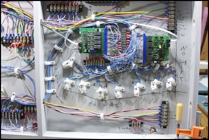
PM42 (left), BDL 168 (right) and RX1 sensors (white) attached to table
In Digitrax’s application note on the PM42/BDL168 (PDF, hidden away in a Knowledge Base article on Transponding) there are a couple of photos showing a system like this mounted to a board that folds down from under the layout. I’d considered something like that in my original design (there’s a small excerpt from one of those photos in the RX4 manual), and decided not to do it due to clearance issues with the storage tracks and electrical power shelf.
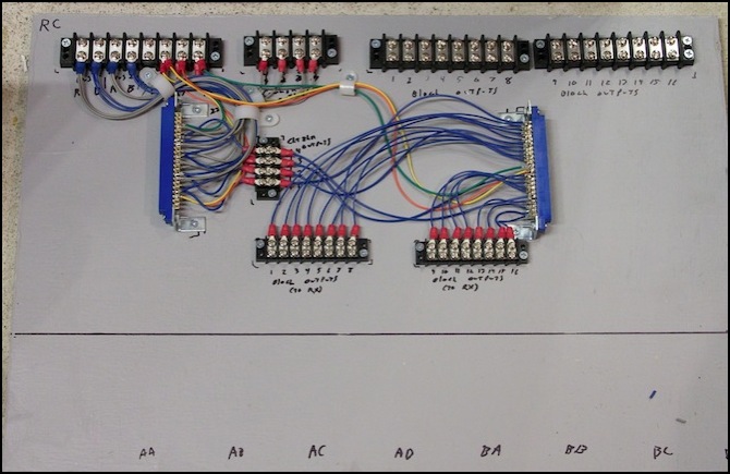
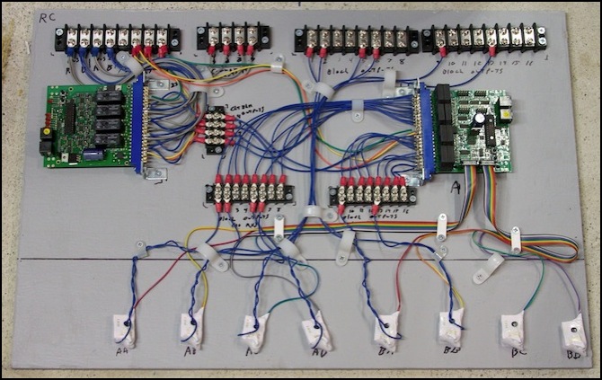
I've now changed my mind, and will work around those problems. So the remainder of the layout was done using separate boards that hang down below the layout, and which (with the disconnection of a couple-dozen screw terminals) can be removed if they need major work done. One of these panels is shown below:
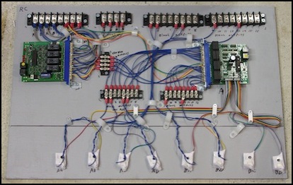
Power Protection and Detection Panel (PM42 left, BDL168 right)
Another interesting thing from this note is the example of wiring PM42's with BDL162s showing both powered by the same power supply (a PS515 powering two PM42s, ten BDL162s and an unknown number of DS54s). This helps to remove any concern I have with using the same "accessory" supply for my PM42s, BDL168s and DS64s). While the note is about the older BDL162, not the current BDL168, there should not be a significant difference in their power needs. One important point is that they do show two additional PS515s being used for track power with the two boosters, so that reinforces the need to keep the track power separate from the PM42 power. In the end, I went with separate accessory power supplies for the set of PM42s (Protection Accessory Power) and the set of BDL168s (Occupancy and Signaling Accessory Power).
Each pair of PM42/BDL168 provides at most 8 occupancy/transponding sections within the bounds of a single table (or in rare instances two tables). This led to more electronics than might have been needed (and a significant increase in cost), but gave me simpler, more modular wiring to facilitate moves, and shorter and less complicated distribution wiring. It was also an annoying amount of work, thanks in large part to Digitrax’s use of soldered edge strips. If I had this to do over, I’d abandon transponding and use circuit breakers and occupancy detectors with built-in screw terminals, to avoid both crimping and soldering, even if the unit cost per device were higher.
Power Supplies
The PM42 and BDL168 both require power to operate. It’s also clear, and I should have realized this, that you can’t power the PM42 from the same supply powering the Booster it’s protecting. The reason appears to be that in a short voltage will drop to close to zero before the circuit breaker severs the connection (that and/or the high current is what causes it to react), and this would affect the operation of the PM42 (you’d think they could do something with a capacitor to ride through this, but apparently they didn’t). So, I can’t use one quarter of my PS2012 for the “accessory bus” as planned. I either need individual supplies (Digitrax's recommended solution, but that's a lot of wall-wart transformers) or an independent but fairly large accessory power supply. I’m going to compromise between the two.
Note: in the PM42 manual they warn not to share a power supply serving PM42s with other devices, in addition to merely keeping the PM42 separate from the track power supply. But they contradict themselves in another note. In an ideal world perhaps each PM42 should have its own power supply. I'm not going to do that, but I'll keep it in mind as a fallback if I have issues with the shared "accessory" supply.
The BDL168 is varyingly described as needing a minimum of “12 volts AC or DC” or “12 volts AC or 13.8 volts DC”, with a draw less than 100 mA. The ambiguity in power requirements is annoying. From the context, I think that 12 volts is safe, and they only said 13.8 because the new PS14 (which replaced the older 12-volt PS12) puts out 13.8 volts, and they’re now recommending use of it. The PM42 is a bit clearer: its manual says 12-18V AC or DC with a minimum rating of 125 mA and they recommend the PS14.
I’ve seen comments that the BDL168 is sensitive to its power supply, so as described on the Wiring Design page I eventually went with a couple of 1.5 Amp 15 V DC regulated power supplies to power the BDL168s (I expect to share these with the eventual SE8C signal controller also). The PM42 will be separately powered to isolate it from the track supply and the occupancy/signaling systems.
Power Panel Layout
The structure of each panel is that it takes as input the two DCC power buses (commuter and subway) and provides up to sixteen outputs to sets of track feeders. One panel will be associated with each table (each "scene" is a set of two tables) which eliminates almost all table-crossing wires.
Terminal strips along the upper edge allow short jumpers to connect it to the underside of the table. And hooks allow it to hinge up out of the way, or drop down to be worked on or removed. It needs to hang two inches below any power wiring to isolated the transponding sensors, but that's easy enough to achieve.
Mounted on the panel is a PM42 providing four DCC circuit breakers, and a BDL168 providing block occupancy detection and transponding. There are also eight RX1 sensors connected to the BDL168 which do the actual transponding detection.
PM42 and BDL168 Wiring
This is an area of significant confusion, both on my part, and from their rather schizophrenic documentation on Digitrax's part as well. How exactly are you supposed to wire these things up? What gauge of wire? When do you bridge pins? What's the capacity in Amps?
While DCC bus wires need to be heavy gauge, typically 14 to 16 gauge, to avoid voltage drop problems (particularly an issue with high-amperage currents from DCC boosters), feeders can be much smaller. Even 22 gauge is safe for 5 Amps, if the wire is short (to avoid voltage drops) and mostly in open air (to allow it to radiate heat from all that current). I was already making use of this by using Kato’s 24 ga feeders (which are safe for 3 Amps; as a result, the trip current for the PM42 will be set to 3 Amp or less). I’d planned to use 16 ga for all wiring to those feeders (which can be several feet in length) to minimize voltage drops, and not being able to attach that to the card edge connectors was a large source of frustration for me.
Digitrax doesn’t say much about wire gauge (aside from a vague reference to 12ga wire being needed “for long wires” in the PM42 manual) for these systems, and it took some digging (and some experimentation) to turn up some facts and a recommendation from Digitrax. The card edge connectors for both the PM42 and BDL168 support 20 gauge wire, although you can use 18 gauge stranded wire with some effort, if you really need to. And hidden away in Digitrax’s documentation is the intent that you’d use short wires of 20ga (or similar) from the edge connector to a terminal strip, and heavier wire from the terminal strip to elsewhere if you need it. They don’t actually say this anywhere obvious though, and I’d missed it on my original pass through the documents that came with the equipment (because it’s not in them).
Let’s start with wiring from the track bus side (which will be 14 or 16 gauge) to the PM42. While you can wire 18 gauge stranded wire to the connectors on these with a bit of effort, it’s a lot easier to use 20 gauge. You need to avoid to avoid long runs of that, but assuming you’re working with a 5 Amp booster, you can stick with short lengths of 20 ga or even 22 ga from the input terminal strip to the input connector of the PM42. On the output side of the PM42 this could be even smaller (i.e., if you’re going direct to track with a 3 Amp circuit breaker trip setting, 24 ga Kato track feeder wire is fine). But it’s simpler just to use the same gauge wire as on the input. Likewise on the BDL168, your wire size should be determined by its maximum current, set by either a PM42 or similar circuit breaker or by the command station or booster rating if you don’t have a separate circuit breaker. Again smaller wire can be used, but it’s easier to use the same 20 or 22 gauge wire used on the input side of the PM42. It’s also good to use the largest wire you can on the longer output side of the BDL168, to minimize voltage drops, although the voltage lost in even a couple of feet at 3 Amps is pretty small. All of this is an argument for using 20 gauge wire with these boards, although for reasons of availability I largely used 22 gauge.
Now for how to wire up the pins on the connectors for the two circuit boards. The PM42 ought to be fairly simple. It has four inputs, and four matching outputs. Each output MUST be wired to one pin of the two provided connector pins (one on the side of the connector identifying pins with letters, and the matching one on the numbered side) unless you are using it for reversing, in which case it MUST be wired to both. Seems simple enough. The input is another matter: each of the four inputs has two pins it can be wired to (e.g., input #1 Rail A can wire to either 4 or D). But the manual makes no mention of this beyond the connector wiring tables (table I and table II). And all diagrams show only the numeric pins wired. There are also two ground pins, but the note only says "at least" one must be wired to the booster ground.
My hypothesis is that both input pins and both grounds should be wired if the PM42 is going to handle large currents, where "large" may mean anything over 3 Amps (see the comment below on BDL168 pin limits). But the manual doesn't say. A flaw in that hypothesis is that the output breakers can be set to trip at loads up to 12 Amps, which suggests the limits for an individual pin must be pretty high (6 amps or more). My loads are going to be pretty low (likely well under 3 Amps except in a short) so I'm not going to worry about this, and will only connect one pin as shown in the manual.
Now for the BDL168: the manual explicitly says that the pins are limited to 3 Amps each, and that they are provided in pairs (one letter, one number) so that current loads up to 6 Amps can be supported. Since I'm setting my PM42 to trip well below 3 Amps, I'm safe in only using one pin here.
Transponding Sensors
The RX1 transponding sensor is nothing more than an inductor through which one of the track power feed wires is run. This can be either an input to or an output from the BDL 168 (in an input, called Zone Transponding, then it's implicitly shared by up to four detectors, on the output it's called Sectional Transponding and can be dedicated to one output or shared by several). Sharing outputs is done by running more than one wire through an RX1, although I believe they all need to be the same phase (since all wiring to the BDL 168 only uses one phase, this is easy enough to do). I attach these sensors to the table with velcro tape, supplemented by a nylon cable loop to hold the wires and one corner of the sensor against the table and in position.
Note: Digitrax sells the RX1 in sets of four on a ribbon cable with a single connector for the BDL circuit board (as the RX4). The BDL168 has two connectors and thus supports up to eight of the RX1 sensors.
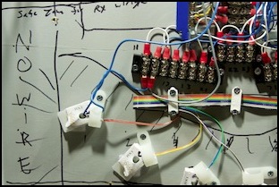
RX1 Transponding sensors (white blocks): top, left has one feed wired through it, others unwired
Transponding is really badly documented. There is some information in the manual that comes with the RX4 (PDF), there’s more in a supplement note that goes with the BD168 (PDF), and there’s the application note mentioned above and various KB articles that touch on the topic. It would appear from the KB article, that it actually is possible to use the same RX1 sensor with two or more blocks by running more than one wire through it, and I expect to make use of that in a few places. These sensors are more fully discussed on the BDL168 page.
Programing the PM42 and BDL168
This is a bit more straightforward. The BDL can use any accessory address from 01 to 999 (the older BDL162 was limited to 01 to 255). It’s unclear what address range is used by the PM42. Both the PM42 and the BDL168 default to address 1 on initial power-up. These need to be changed to be unique, and to avoid confusion none of them should use address 1, that way if I ever see address 1 in use, I’ll know I forgot to program one of them, or it somehow reset to the defaults and needs to be fixed.
Note: actually, the BDL168 uses 16 addresses, although Digitrax’s documentation is remarkably unclear on this. See my LocoNet Addressing page for details.
Changing the address requires using a hand-held Digitrax throttle plugged directly into the unit, see the manual for details. Note, however, that pressing the button to put the unit into address programming mode doesn't always work, so you may have to try repeatedly. Also, the PM42 needs a second press as described in its manual to complete the process, otherwise the address isn't changed. But on the BDL168 the address change is instant. Also, this does not appear to be something that can be done through the programming panel in JMRI, where you can read and set option switches, but not change the address.
And on a related note, I could never get JMRI to successfully read all of the BDL168's option switches. Sometimes it would get hung up on 9, other times on 12 or 26, but it never did more. This may be due to the old (and slow) computer I’m using, and could be a sign of future problems. Fortunately the PM42 programming seemed to work reliably, and I don't need to change much on the BDL168.
What I changed:
PM42: Address; Trip current to 1.5 Amps; All four zones to "fastest".
BDL168: Address; 39=c, set verbose transponding (same address in multiple zones)
Board Construction
As noted above, I'm building a number of these circuit-breaker/occupancy-detector sets, six in all for now (plus a seventh circuit-breaker-only element on the outer loop's DCC feed). Two of these were installed under the Riverside Station scene (see photo at top of page). The others will go below the Urban Station scene (two), the Riverside Crossing scene (one) and the unsceniced return loop.
Three of the boards (the two Urban Stations scene ones and the River Crossing scene one) are going to be nearly identical, and I’m building them first. These will be designed such that I can rearrange the transponding sensor assignments or the circuit breaker to detector association in the future, just by moving some wires between terminal strips. As such, even through they’re supporting different configurations, 90% of the work will be identical on all three. And I’m building all of them to support use of all 16 BDL168 outputs, even though two of them need only seven and the third needs only six today. The final board, for the unsceniced end, needs a slightly different design due to the lack of space off of the board for terminal strips; it’s going to need more wire and terminal strips on the board, and hence will be larger as well, but it can also mount to one of the support frames, which makes things a bit easier as well. I’m going to do the three identical boards first.
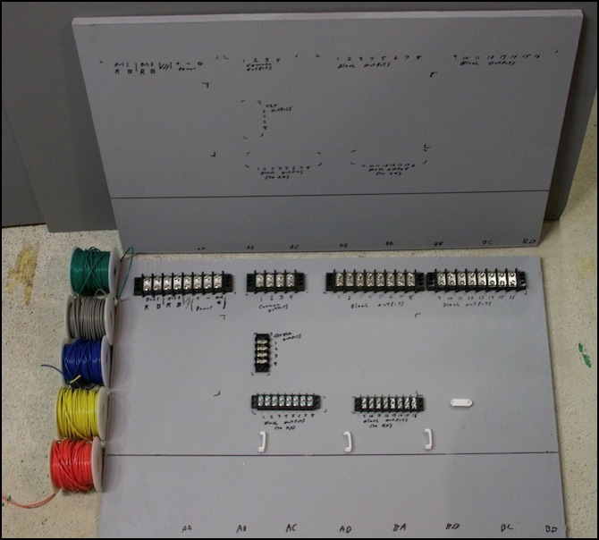
After I laid out the positioning of the terminal strips, circuit boards and RX1 sensors, and marked the first board, I copied the markings to the two other boards as seen in the photo below (which also shows my collection of 18 gauge wire; none of this wire is long, so use of small gauge wire acceptable as voltage loss will be minimal. I used 18 ga on the input to the PM42 (and on the output although I'll probably change that on future boards) since these could carry 5 Amps of power. But this is hard to solder to the card connectors, and so I used 22 ga wire elsewhere on the board because I didn't have a supply of 20 ga. wire.
Although the RX1 sensors only require a two-inch center-to-center spacing (by one reading of the manual, another section suggests two inches between them is needed), and that's what I used on the underside of the table, I'm using a 2.5 inch spacing on these boards since I have the room. In the photo below, the space below the horizontal line is the "no power wires" section reserved for the eight RX1 sensors. The strips at the top are used for short jumpers tying the board to the table above it. The PM42 will mount to the left, and the BDL 168 will mount to the right, just below the upper row of terminal strips.
I'm using two different kinds of terminal strips here. The big ones along the top of the board come from Home Depot, and use #8 screws (and need #8 spade lugs). The smaller ones in the middle come from Radio Shack and use #6 screws and lugs. I could have used either in both locations, but I like the compactness of the smaller ones for the dense wiring in the center of the board, and I prefer the larger ones for under-table wiring as they're easier to work with in cramped spaces and at odd angles with poor lighting.
With the terminal strips attached, I mounted the angle-brackets used to hold the blue card-edge connectors, and began cutting and soldering wire. None of it was screwed down until the last wire on the connector was soldered, then spade lugs were crimped on, the card edge connector mounted to the brackets, and all the spade lugs screwed to the terminal strips.
After that, the boards were installed, and the RX1 sensors mounted. Then I installed the wires that go from the output of the BDL168 though the RX1 sensors to the output strips at the top-right of the board. In this example, used on the River Crossing scene, only six outputs are used. See the block list on the Wiring Standards page for a list.
Testing
I ran a number of tests using my test track connected to the first board, to get a feel for how the units worked and what kinds of messages they reported over LocoNet. I used JMRI's Monitor Loconet window. Here's the initial output at power-up of the detection board (the Zephyr was powered up earlier, so you don't see its start-up messages here):
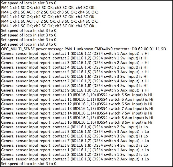
Note that the first number after the "PM4" is the address of the PM42, in this case "1".
Also, with the BDL168, the first number after the "BDL16" is the board ID, in this case also "1" as in “BDL16 1,4" however this maps to an address based on the board ID and output number.
On the BDL168, the 16 detectors are reported both as the number pair (e.g., "1, 4") and as the status of an imaginary DS54 "Aux" and "Sw" input. The latter increment with the address, so BDL168 #2 contact 1 reports as "BDL 2, 1" and "switch 9 Aux". But there’s a third number, given after the “contact” keyword, which is the actual accessory decoder address, and this is waht typically needs to be used in computer-based control systems. So, for example “contact 3 (BDL16 1,3)” is addressed in JMRI as LocoNet Sensor LS3. And a hypothetical “contact 34 (BDL16 3,2)” would be LS34.
On the PM42, you can see the status of the circuit breakers ("OK" meaning normal, "ACT" meaning the breaker has tripped although it apparently does this at initial power up even when the block is clear). I haven’t yet figured out if the channel numbers equate to unique accessory decoder addresses or not.
