


DCC Basics: An Overview
This isn't really the place for a tutorial on DCC. There are plenty of books and magazine articles for that, not to mention online information. The NMRA has a number of pages aimed at beginners, for example, and you can no doubt find many others.
But there is some basic information worth noting as an introduction to the other pages in this section. For detailed information about DCC decoders, see the DCC for Model Trains subsection of the Model Trains section. For information about the DCC systems of my layout, and a few more in-depth pages about specific topics I’ve had to delve into for it, see the Electrical Systems pages in The Model Railroad.
DCC Components
A DCC system is composed of at least five parts: the throttle, the command station, the power supply, the power station and the decoder. Some of these parts may be combined (in fact, many beginner systems combine the first four parts in a single device). Additionally, there are optional parts that can be included, such as additional power stations (called boosters), a control bus, circuit breakers, and specialized devices such as block occupancy detectors, and stationary decoders for functions such as turnout and signal control.
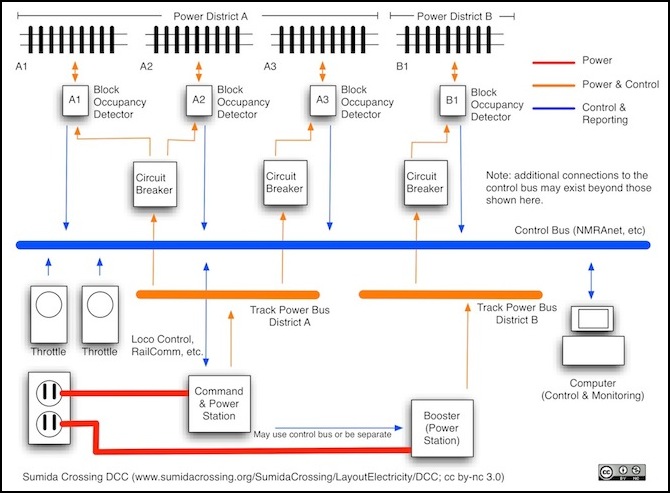
DCC System Components
Train Control
The throttle, also sometimes called a “cab”, is the set of controls used by a human to give commands to a train, such as adjusting the throttle, setting direction, controlling lights, or (for a train equipped for sound) ringing the bell. Some throttles are wireless, using radio to connect to the command station, others are "walk around" throttles that plug into suitable jacks distributed around the layout. One important aspect of DCC is that once a train has been told to run at a given speed, or stop, the throttle can be unplugged while the user walks to the next location, and the train will continue executing the last instruction it was given. A throttle may be part of the command station (a knob, pushbuttons or a lever on the box), separate but wired to it in some fashion, or it may utilize a control bus to communicate with it.
The command station takes commands from one or more throttles and converts them to DCC form. These are then mixed with the power needed to run the train's motor (which comes from the power supply) by the Power Station and sent to the track. The first Power Station is usually incorporated in the Command Station, but can be separate. If more power is needed than can be supplied by the first power station (separate or part of the command station), then additional separate Power Stations can be added and these are called “boosters”.
Between the Power Station and the Track will be at least one Circuit Breaker. The first is built into the power station (or the command station if the two are combined) and protects the total power sent to the entire layout. But it is often useful to subdivide the track into blocks with their own dedicated circuit breakers, so that a short circuit (such as is caused by someone running the wrong way into a turnout set against their train) will only affect a portion of the layout.
The decoder takes the power and signal from the track, and uses signals addressed to it, and only those, to control the motor. Because each train has a unique number, a decoder can tell which commands are being sent to it and ignore the others, and this allows more than one throttle to control more than one train. In fact, the command station remembers the last command sent to a train, and keeps re-sending it, so an operator can unplug their throttle, or change it’s address to control another train, and the first train will keep running. This allows one person with one throttle to control multiple trains.
Interoperability
Because of the way DCC was standardized, buying a DCC system from one manufacturer doesn’t lock you into buying decoders or other parts from another, but there are limits. Typically the link between the throttle and the command station is proprietary, meaning that the throttle has to come from the same manufacturer as the command station. The link from the command station to booster isn’t necessarily proprietary, although it’s often easier to use boosters from the same manufacturer anyone with minor wiring skills can use one from someone else.
There isn’t a standard control bus today, although there is some work to standardize one, so anything that depends on one is to some extent locked into use of that system. This doesn’t necessarily mean just the one vendor however: Digitrax’s LocoNet supports products from a number of vendors, and doesn’t require a Digitrax command station to be used. But it’s somewhat limited in choice due to their licensing requirements. What this typically means is that things like occupancy detectors may require their own communications method back to a computer, in parallel with an existing control bus if, for some reason, you don’t want to use models designed for the control bus on your system (or if your system doesn’t include a control bus; not all do).
Finally, as noted boosters are simply amplifying the DCC signal, and that means anyone’s booster can be used with anyone’s command station, although you may need to wire up the correct kind of connector, and figure out what wires go where. But there are often instructions online, either from the manufacturer or others. Circuit breakers also don’t depend on the command station, so you can add ones made by anyone. However, if you want the circuit breaker to report to the computer when it trips, or if you want to use one that incorporates other functions (like occupancy detection), then you would need to take your control bus into account for that aspect.
Decoders, however, are universal. Anyone’s DCC decoder will work with any DCC command station. Note that there are some digital control systems out there that aren’t DCC (the term “DCC” is a trademark of the NMRA and can’t legally be used to describe anything else). There are some limits in practical terms: trying to run N-scale trains with a DCC system designed for garden railways is likely to damage the trains due to the higher voltages used. But technically the decoder for an N-scale train will work with the commands from a G-scale command station; it’s just that the voltages on the rails are different.
Other Control Feedback Systems
There are two kinds of feedback: that from trains, and that from accessory devices.
Trains can send feedback back to the Command Station through the rails using RailComm. Digitrax has a similar, proprietary system called Transponding in its decoders and command station. Both the command station and the decoder need to support RailComm or Transponding (and it’s an either/or choice; I’m not aware of any systems or decoders supporting both). However, you can add RailCom to a train that lacks it or has a decoder with Transponding (assuming you turn off transponding). Lenz mades a RailCom-only decoder (the LRC100) that can be added to a train with an existing decoder to add RailCom support.
A Control Bus is a system separate from the DCC signals that allows devices on the layout to communicate with each other. This is superior to simply using stationary decoders, since it will typically support a greater amount of information being exchanged, and can be interfaced to other communications systems (like a radio unit for wireless throttles). The NMRA is beginning to standardize NMRAnet as its control bus, but this is recent. Several existing DCC manufacturers have developed their own control busses, such as Digitrax’s LocoNet or Lenz’s XpressNet.
If the system has a control bus (or a “feedback bus” used for feedback only) devices, such as block occupancy detectors, can send information back to other devices. This is probably most useful if a computer is also connected to the control bus. However, it can also be used for other purposes, such as a set of crossing gates than come down when a train is detected approaching, and go up when it passes. In that application, two occupancy detectors (one on each side) communicate with the controller that drives the motor raising and lowering the gates.
