


Suburban Hilltop Scene Construction
Calling the end with the return loops “rural” would be overstating things a bit. Although the scenery here consists of a wooded hill surrounded by houses and topped by a temple. It’s not an uncommon sight in suburban areas where land simply isn’t suitable for building most kinds of structures, or at least wasn’t prior to the advent of modern machinery.
The idea is to hide the return loop tracks away so they don’t look like a loop, and provide a visual end to the two adjacent scenes, the Urban Station and the Riverside Station.
But this is a recent change in plans (c. late 2012) and originally the intent was not to add scenery here at all, beyond a simple viewblock. Early construction thus created some problems I had to overcome when it came time to finally build the scenery.
In the diagram below, black lines that don’t cross tracks (or mostly don’t cross tracks) are scenic blocks or backdrops, while black lines crossing tracks are marking insulated joints (ignore the vertical black line in the middle, it’s just a two-foot interval mark). The Urban Scene is to the left on top, and the Rivserside Station scene is to the left on the lower side.
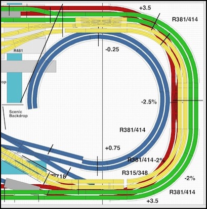
Original Track Plan (red is subway, blue is helix)
Early Construction
This end of the layout was originally envisioned as a “behind the curtain” place where the trains looped from one side of the layout to the other unseen, leading it to be called the “unsceniced end” and similar names. The end was to have two levels, but instead of being tables supported by a frame, these would be plywood cut “cookie-cutter” and supported by risers from a rectangular inverted L-girder box that was open in the middle. This box would lay atop the supports, and be removable as a 4’ x 4’ x 6” structure (which would fit atop a car, along with some of the support legs, rather than being sized to fit inside).
Construction on this commenced very early, in November of 2009 and by December the cork on the first layer was being glued down. Work then paused while my attention turned to other parts of the layout, and the end remained a single level for some time.
Cork for the “unsceniced” subway loop (December 2009)
Subway Loop with cork and track
Upper Level
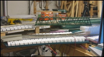
In April of 2010, work commenced on the second level. Supports for the second level were quite simple: In some locations a small length of 1x3 was screwed to the side of the L-girder, with the layer above screwed down into the end of the 1x3. This was the same method that had been used for the lower level, but it only worked where the L-girder wasn’t blocked by the subway level above it. In most places this wasn’t practical, and the 1x3 were instead attached to the lower level by screwing up from below. Once finished, cork was added and track was in place by the end of May, although work on adjacent scenes to connect it continued into June. In early June the “first run” was celebrated on the subway line, with the upper level structurally complete but not fully wired up (see the “First Run” video on the Movies page).
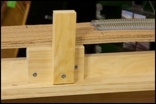
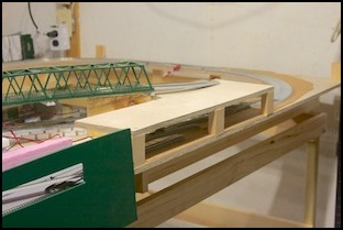
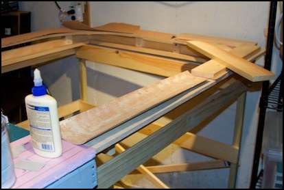
Supports for the second level
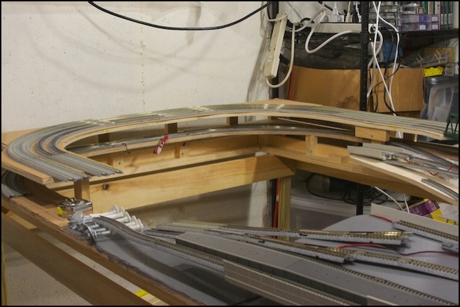
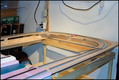
Second Layer tracklaying (May 2010)
Extending the Scenes
As part of this work (in April-May 2010), the ends of the two adjacent scenes were extended into the return loop to create a transitional area. The idea was that an angled backdrop would be created for each, hiding the loop and providing a visual block. That backdrop was never built, and the loop remained visible for years.
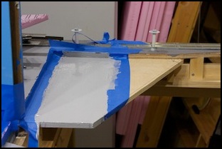
The Urban Scene extension was to create a small canal with a bridge, providing a reason for the buildings and tram line to end, and a way for the main avenue to continue. The upper viaduct station would continue over the canal, as this part was used for the switches that opened the four lines up to six and spread them apart around the station platforms. The same 3/4” lower layer of foam was used here, but first a quick visual test using a ruler and two cars was done to see how the scene composition would work from various angles.
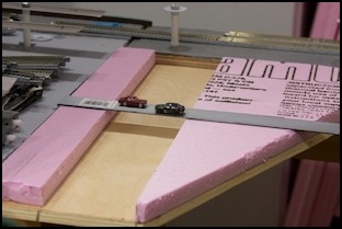
Urban scene extension
The section under the canal was then primed and painted. Foam would later be added, but I neglected to photograph that portion of the early work.
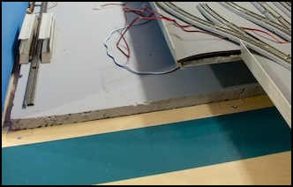
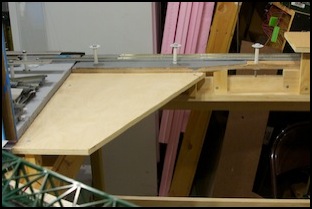
Opposite this, similar work was going on at the end of the Riverside Station scene. This section would eventually provide the place where tracks connected to the subway line and the top of the helix, out of sight under the bridge leading from the upper-level station to the return loop (a viewblock below the bridge would hide most of the trackwork. Aside from the outer commuter loop, the upper section wasn’t ready on the rest of the layout at this time. And the subway line connections to the Riverside Station were never put into service, as that station was still under construction (and remained so for several years). The two scene extensions remained there, used mostly for storing tools and supplies, and work on the backdrop (or scenery more complex than a layer of paint never happened).
Riverside station end with primer (left) and test-fitting track (right)
And that’s how things remained for two and a half years, until inspiration struck. Well, almost. I did have one addition in that time.
The Computer Display
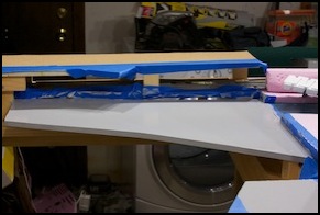
Underneath the Riverside Station scene, adjacent to the return loops is the electronics shelf. One of the things there is an old Mac Mini I’m going to use for layout monitoring and automation. One of the first things it will have is a track plan display connected to the occupancy detectors via JMRI software (if I ever finish the DCC power panels). And for that, I needed a display that could be seen from the layout.
I hit on the bright idea of mounting a monitor on a swivel base that would allow it to be viewed from either side of the layout. This required a post to attach the swivel to. The original version was intended to be out of sight behind the viewblocks, so I simply bolted a spare 2x4 to the support frame, and attached the monitor arm (an Ergotron) to it. This was not well thought out, and I didn’t allow for the rather substantial weight of the swivel arm, and over time the support frame actually bent and the 2x4 tilted out into the open area of the future helix. Not far, but enough to affect the monitor. And I was afraid it was going to break the support structure, which is a simple 1x4 not supported by anything else in that location.
So I modified this to use a 1x4, anchored it to two of the support 1x4 boards, and painted it before mounting (in my usual neutral gray color). It’s still a bit awkward to look at, and I’ll need to find a way to hide the support (the monitor itself can be swiveled to the other side of the layout if I want to take photographs or look at the scenery). But it’s a big improvement over what was there before.

The Computer Monitor
The Hilltop Scene
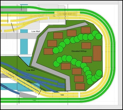
My bright idea, spawned by one of many discussions about urban temples in Japan on the JNS Forum, was to put a “lid” over the future location of the helix, and scenic it. This would simultaneously provide a transition from the adjacent scenes into something else, more gentle than a viewblock, and rise above the level of the upper-level tracks, concealing their presence. The lid would replicate a low hill, with steep sides covered with trees and a flat area atop it with a Buddhist temple or a Shinto shrine (Japan’s other major religion). The lower flanks of the hill could have a small road and some houses to make a transition from urban to suburban.
Here’s the revised plan (compare with the original at the top of the page), with the subway and helix hidden from sight. The blue tracks at lower left are the transition from the station into both the subway and the helix. As before, a viewblock under the bridge hides most of this track from casual viewing from the other scene. The exact layout of the rivers hasn’t yet been decided.
Backdrop
The first order of business is to make the backdrop. Formerly the track just butted up against the wall (as seen in the Computer Monitor photo above). Actually, there’s a small 3/4” (18mm) gap there, just enough room to fit a 1x3 support down to hold up the backdrop. Unfortunately the plywood holding the track sticks out about 3/4” beyond the frame under it, so I need to attach some spacers between the frame and the backdrop supports. Since it’s almost touching the wall, attaching these would be hard; I really don’t want to disassemble the whole “unsceniced” end just to screw a couple of blocks of wood on. But I don’t actually need to, I just need to thread the bolt that holds the backdrop in place through them, and that will keep it from falling out. A small square of 1x3 lumber will do for this.
The backdrop itself is made in the usual fashion: cut some “tempered hardboard” (aka Masonite) to size, glue a couple of 1x3 to the back, sticking down about 7”, and drill through the frame, the spacer and the 1x3 support, then stick a 1/4” carriage bolt with some washers through, and tighten a nut on the end. The backdrop will be painted with primer to seal it, and a photo glued to the front.
The left corner at the back actually has a cut-out to accommodate a wall-mounted electrical outlet box, so the width of the backdrop will be 45” rather than 48” (114 cm vs 122 cm), and it will be 24” (61 cm) high. I need to choose an appropriate photo, however this will only be seen from a distance behind the scenery, so it doesn’t have to be a highly-detailed one. I want something that suggests “distant urban view from above”, but without large towers (I have enough of those on the other backdrops).
