


L-Girder Construction
Open-grid support structures can be built from simple dimensional lumber (e.g., 1x3 boards, etc). But a more common technique in model railroading benchwork is the L-Girder method. This uses a set of supports built from dimensional lumber, held up by table legs or wall brackets to support L-Girders crossing them at a right angle (or sometimes a less-than-right angle), and then the girders in turn support joists crossing them at any angle. Joists are used as attachment points for risers holding up the actual subroadbed or scenery.
And, while the original method used dimension lumber, a more recent technique is to cut “boards” of the usual dimensional sizes from 3/4” (19 mm) plywood, as this is less prone to warping than ordinary lumber. Screwing into the edge of pine requires a bit more care (drilling pilot holes is mandatory, not just a good idea), but the extra work pays dividends in the long term.
Why do it this way? Well first, an L-Girder can span about twice the gap that a simple board stood on edge can without bending. Second, L-Girders are less prone to warping than a simple board. And finally, the system of support, girder and joist is very flexible, allowing complex scenery and very solid railroad subroadbed to be easily constructed with a minimum of lumber.
And it also allows the benchwork to be easily reconfigured, since most of it is simply screwed together. This is useful if you discover three years into a project that you want to rearrange a section, and the joists are in the wrong place for the new track or scenery.
Where L-girder doesn’t work is when building multi-deck layouts. The extra vertical space required is just too much. It’s also not really necessary in a shallow shelf-type layout (although some people have used it for those, likely because of its flexibility, and I am giving it consideration for my future shelf layout. And it’s really not suited to a modular layout, although there’s really nothing stopping someone from using it for one (except possibly formal module standards if you’re part of a club).
Some Basic Numbers
This section recaps some essential numbers from the rest of the page for ease of reference.
Typical L-girder top: 1x2 dimensional lumber.
Typical L-girder vertical: 1x3 dimensional lumber (also 1x2 and 1x4).
Typical L-girder span length: 9.5 feet (2.9m) or more with 1x3 vertical.
Max L-girder spacing: 4.5 feet (1.1 m) for 1x3 or larger joists.
Max Joist spacing: 16 inch (41 cm) recommended (see below)
Min Joist spacing: the room needed for your electric screwdriver or drill.
Joist spacing is very dependent on what it’s supporting. The most rigid requirements say 16 inches for 3/4” plywood subroadbed (closer for thinner subroadbed). However, many modelers use larger spacings up to about 22 inches (56 cm). For minimum spacing, my limit is 12” (31 cm), but I’d probably pad that a bit to allow room to work.
The height of the layout’s “surface” is very dependent on the builder’s goals and subjective evaluation of what “looks good”. Some people prefer to have the track close to eye level, while others like to look down on the trains. Height also affects reach: it’s harder to reach into the back of a layout above waist level, so some people try to put large yards at a lower level. Some module standards call for a 40” height of rail top above floor. I prefer higher benchwork myself, but I’m tall. If you have younger children (or grandchildren), heights below 40” may be desirable. L-girder benchwork can support any of these heights, but it’s best to know what you want before building the wall brackets (or legs if you’re doing a free-standing layout), as those will ultimately limit your height.
An L-Girder Shelf Layout
I’m going to summarize the basic L-girder wall-supported method I’m considering for my next layout. However, there’s a lot more to L-girder work than what I’m saying here, and many useful variations on it. If you plan to use L-girder, I strongly recommend doing some reading. In particular, Linn Westcott’s book How to Build Model Railroad Benchwork (2nd Ed., Kalmbach, 1996) is the bible for this. It may be out of print, but used copies are easily found at train shows and online. There are many more recent books on benchwork, some well worth reading, but I haven’t found another that really gets into the details of all the ways to use L-girders as Westcott does.
Note: Kalmbach’s more recent Basic Model Railroad Benchwork, 2nd Ed., by Jeff Wilson provides a good overview of various kinds of benchwork, and as of the 2nd edition incorporates material from Westcott’s book, including some of the diagrams. Where it falls short is in the coverage of dimensional lumber, with no discussion of strength or why to choose different sizes, and in a shorter coverage of L-girder use. What it covers, it covers well, with more and better photos and many diagrams. And it has good coverage of other methods, as well as subroadbed. It’s worth owning. But if you plan to use L-girders, do yourself a favor and hunt down a copy of Westcott’s book.
Wall-hung L-Girder benchwork
Screws
Drywall screws are cheap, and while not really very good screws they’re perfectly adequate for most layout benchwork. I resisted using them for years, preferring to buy good wood screws, until I actually tried some. You’re going to use a lot of screws in benchwork, and if it’s hidden away where nobody sees it, it doesn’t need to be pretty. If you’re attaching fascia with a screw someone will see, by all means spring for the extra cost. Otherwise, buy a big box of the right size of drywall screws; it’s a sensible economy.
Drywall screws are typically thin, but with fairly broad heads and wide threads for their size. As long as you’re working in softwood they do a very good job of holding it. They are, after all, designed to screw through drywall and into pine, and hold the soft drywall in place against the pine. They’re weaker than normal wood screws, and using them in hardwood they’d likely break more often (even in softwood they sometimes snap, at least when using an electric screwdriver with a good bit of torque behind it). If you break one, just move over a 1/2” or so and put another in.
Drywall screws come in a variety of lengths and typically in #6 (9/64” shaft) or #8 (11/64” shaft) sizes (that’s American measure; I don’t know what’s typical elsewhere). They also come with coarse or fine threads; coarse is preferable for softwood, and benchwork is typically softwood (pine, etc).
If you’re working with 1” thick dimensional lumber and 3/4” pine (both of which are 3/4” or 19mm thick) a 1 5/8” drywall screw will just stick out the far side, while a 1” one won’t get very much purchase on the second piece of wood. A #6 1 1/4” screw would be ideal.
Note: for L-girders, a slightly longer screw is recommended to attach the top of the girder to the body of the girder, see below. But using a 1 1/4” one wouldn’t significantly weaken the girder, since the screw mainly serves to clamp the wood while the glue dries (it does provide a bit of lateral strength as well). That means if you want to save money, just buy one size screw and use it for both.
Always drill a pilot hole sized for the screw’s shaft. For a #6 that’s 9/64” (3.6 mm), and the depth should be most of the length of the screw. You want the threads to bite into the wood, but you don’t want the shaft to push the wood aside (which can lead to a split, now or later, due to stresses created in the wood’s fibers). A reversible pilot-drill/screwdriver bit that can be set for the depth of the screw and which has a flange to create a wider “countersink” hole for the screw head is a very handy thing to have, and I’ve used one on all of my benchwork.
I usually clamp the wood where I want it with a quick-release clamp, drill the first pilot hole, flip the bit over and screw in the first screw, and then repeat for the second. If space is tight, I might release the clamp after the first screw, counting on the first screw to hold things long enough to get the second in where I’d placed the clamp. While that sounds complex, after the first hundred screws you won’t even notice it. And there are going to be a lot of screws in even moderately small benchwork.
The Girder
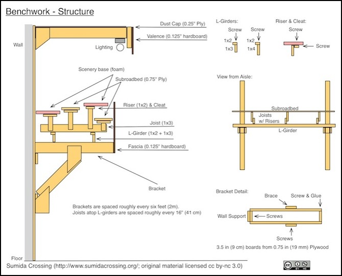
In essence an L-Girder is two dimensional boards bonded to form a much stronger structural beam. The horizontal top board is typically a 1x2 (0.75 in x 1.5 in, or 19 mm x 38 mm) and the vertical board can be a 1x2, 1x3 (57 mm wide) or 1x4 (76 mm wide). However you need sufficient “face” on the side of the girder to attach risers with a pair of screws, so 1x3 is really the minimum size to use in most situations. The flat part is on top, so it can support joists, and screws can be driven up into the underside of the joist. It also functions to keep the beam from twisting or “rolling over”, which would substantially reduce the possible load it could carry.
As with other “boards”, cut plywood can be substituted, although 3/4” (19 mm) should be used to gain the full strength of the girder.
The vertical part is screwed to short vertical boards (1x2 typically) connected to the support structure. When these are above the support, they’re called “risers”, below it “hangers”. but both serve the same function. The word riser is also used for short verticals connecting subroadbed to joists. An L-girder suspended by hangers or lifted up on risers is only as strong as the weakest hanger or riser connection. For that reason, L-girders normally rest atop the structural support, with the risers used only to keep them from moving.
To form an L-girder, a bead of carpenters wood glue (yellow glue) is run across the top of the vertical board, and then the top board is laid above this, with it’s edge flush with one side of the vertical board, forming an inverted “L” shape, and clamped in place. Then screws are driven through the top board an into the upper edge of the vertical board. Make sure they snugly pull the wood together along its length, without any gaps. Westcott recommended using 1 5/8” drywall screws every foot or so along the girder. You don’t need to clamp this once the screws are in, because they do the clamping for you, so one set of clamps can be used to build a large quantity of L-girders in a short time.
Note: you can use white glue in place of yellow carpenter’s wood glue, since L-girders aren’t likely to get wet (white glue is water-soluble, yellow glue is not). But it’s generally best to use carpenter’s glue, to avoid any potential weakness (a dripping pipe, for example, could permanently and invisibly weaken a girder even after the leak was fixed and the layout repaired).
It’s best to drill the pilot holes before putting the glue on, so you don’t gum up your drill bit, but this will require a bit more care in clamping things so the holes line up.
Per Westcott a girder made with a 1x3 vertical can span up to 9.5 feet (2.9 m), but this is assuming you’re building a table large enough that someone might need to climb atop it. For a simple shelf layout even a 1x2 girder can span fairly large distances given the light weight it will need to support. However, the longer the span the more things can move due to vibration or unexpected jolts, so supports under the girders should be closer than the absolute minimum.
Parallel L-girders need to be close enough to support the joists, but not too close. This is covered in the next section.
I expect I’ll be conservative and use supports every six feet or so (about 2 m). I need to work a bit more on the design though.
When girders are attached to risers or joists, screws are normally used without glue on those connections, so that the benchwork can be taken apart later if something needs to be moved.
L-girders are not normally painted, since they’re hidden under scenery. However, you can paint them after the glue has had time to set (a few days) since things attached to them will be using simple screwed joints. Don’t paint before gluing, as that will block the pores used by the glue to form a strong bond. If you do paint them, allow it to fully cure before using the girder. For primer, a few days to a week will do, depending on humidity. For finish paint, curing can take more than a month. I don’t plan to paint my girders.
The Joists
Joists are run across the L-girders, and are simply dimensional lumber (boards) or plywood cut to the same size) standing on end. They’re screwed to the L-girders to hold them in place, and their purpose is to support everything above them: track and scenery.
Because they’re simple dimensional lumber, they need to be supported fairly frequently: for a simple 1x3 this is about every 4.5 feet (1.1 m). While 1x2 lumber can be used as a joist, that doesn’t have much side to which to screw risers, so I’d treat 1x3 as the normal minimum size. And unless you’r building very large tables, that’s all you need.
It’s also important that the joists not be too close to each other. Keep in mind that you’ll need to get between them with power tools (e.g., an electric screwdriver) when attaching or moving risers or otherwise connecting things above to the joist. Also, while you’d normally run wires under them, or pre-drill them for wire-ways, you might need to put a hole through one some day, so leave room to get in there with a power drill and a hole saw or Forstner bit (see my tools page). However, there’s also a spacing limit due to the need to support the scenery and subroadbed fairly frequently, see the next section for that detail.
My larger, battery operated, drill needs about 12” (31 cm) of space. I’d probably keep to a minimum spacing of 14” or so to allow some room to work. When driving screws my electric screwdriver can work in a smaller space, so the drill is the limiting factor.
That same argument applies to the L-girders. They need to be close enough to each other that the chosen size of joist can span them (e.g., the 4.5 feet mentioned above for a 1x3), but not so close that you can’t get between them with a power tool.
Subroadbed, Etc.
Risers are typically made from 1x2 or 1x3 dimensional lumber, although you can use larger sizes, or just cut them from plywood (probably in sizes larger than 1x2). An individual riser isn’t carrying much weight, so it doesn’t need to be very strong, unless you plan to stand on the subroadbed, which isn’t really a good idea. They do need to be stable though, so you will need to attach them to the joist with two screws so they can’t pivot.
Risers connect to the side of the joist (with screws) and hold things above them. If that’s subroadbed, it can be attached to the riser by screwing a small block of wood into the side of the riser, called a “cleat”, and driving a screw down through the subroadbed into the cleat (be sure the screws don’t hit each other). Or you can attach subroadbed (or other scenery to the cleat with glue. Or you can simply rest it atop the riser with or without a cleat.
Different length risers can put track (subroadbed) and scenery at different heights. The reason joists need to be placed every 16” is that subroadbed needs to be supported roughly every 16”, so that’s where the risers will be. For added strength or stability, risers often have sideways 1x2 boards at their top, called cleats, to which the subroadbed is actually attached.
Building a shelf layout with L-Girders
Shelf layouts are often simply attached to a wall with small brackets. Why get more complex?
First, because some parts of my layout will stick out 24” (61 cm) or more at the end of a peninsula, which is fairly wide for a shelf. Second because I want to avoid a “flat” layout, and L-girder/joist construction makes it easier to have separate tracks at different heights, as well as allowing for scenery to dip between them. Also, as you can see in the diagram above, putting the “ground” on relatively tall risers lets me fit in a subterranean level of track, for a subway line.
So my current thinking, still subject to revision, is to put brackets I make out of 3/4” plywood cut into boards along the wall, roughly every six feet (2 m) and run a pair of L-girders parallel to the wall above them, and about 14-16” (36-41 cm) apart. If the layout gets very wide, I can use three L-girders, but I suspect that won’t be necessary. Then every 16” (41 cm) I’ll place a 1x3 joist above the L-girders sticking out towards the aisle. Risers from the joists will hold up the track and scenery.
There will be a fascia on the front, attached to the brackets and to some of the joists (probably not to all of them). This will have cut-outs where I want to display the subway line.
The space under the layout will be left open for access to wiring (which will mostly be along the wall where it’s easy to work on), but I’ll be able to stack small storage bins or keep rolling shelves under there as well. Extra storage for supplies, models, and not-presently-in-use trains will always be needed.
Valence and Lighting
And above everything will be an upper “cap” to keep dust off and hold up and reflect the lighting fixtures, with a valence along the front so you don’t see the lights or supports. This will leave about an 18” (46 cm) opening between valence and fascia for viewing the layout.
It’s important to have the Valence further from the wall than the front of the layout (i.e., the fascia), so that light from the lighting fixtures behind the valence falls on the front of any models near the edge of the layout, rather than casting shadows in front of them.
It’s also a good idea to paint the inside of the valence and the dust cap white, so that the maximum amount of light is redirected towards the layout. This isn’t as necessary if you use spotlights or other focused lighting fixtures, but the normal lighting method is fluorescent tubes, and those throw light in all directions. Putting a plastic diffuser around the bulb will also help make the light more even, as well as eliminating any paint-fading ultraviolet (UV) that may leak out of the tube. Most quality modern fluorescent tubes shouldn’t leak UV, but this depends on the quality of the bulb manufacturing, and some do.
Work Areas
To prevent people from resting things (papers, models, tools, cups) on the layout, horizontal surfaces need to be provided that can serve as work areas. Cupholders are also probably a good idea, but need to support coffee-mugs as well as beverage cans and typical cups. Work areas should be located where they are convenient to use, but intrude on aisleways as little as possible, so it is likely best to position them to one side of yards, stations or other areas needing the widest benchwork, rather than where the aisle will be pinched to its minimum size. There are two main kinds of work area: desks for seated use, and shelves for standing use.
Work Desks
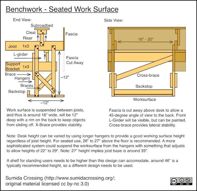
The “ideal” height for a desk depends on the height of the user. Adjustable desks usually fall in the range of 22” to 29” (56 cm to 74 cm) in the U.S., but other countries may have other typical ranges. A good compromise height for typical U.S. users is 26-27 inches (66 - 68 cm).
While a small desk could simply be placed below the benchwork, and this would have the advantage of being movable for construction work, the valence will tend to block visibility unless the desk is pulled out into the aisle, further intruding on aisle use than the seated user already does. So it is probably better to build a work table as part of the benchwork, and cut away a portion of the valence to enhance visibility. The following diagram shows how such a work surface could be built with the along-the-wall benchwork outlined above. This would be suspended between two joists, which limits the width to the joist spacing, and a depth over 12” is probably impractical due to sight lines and non-movable objects like L-girders. Since this is also a good depth for paper pads, that’s likely to be the depth used.
Note: although not shown, a lighting fixture could be attached above, connected to the L-girder. Also, a flat-panel monitor could be attached to the back cross-bracing. However a width of 16” is inadequate for a full-size keyboard and mouse, so this kind of desk shouldn’t be used if extensive keyboard work is needed. The desk will work for typical laptops, compact keyboards, or tablet computers.
Standing Shelves
It is also important to have work-surfaces suitable for standing users, otherwise people WILL put things like tools, models and coffee cups on the layout itself. A typical recommended height for standing use is around 46” (117 cm), although again this depends on the height of the users. A typical layout surface height can vary quite a lot, even on a single-deck layout. Some people like low surfaces best viewed from a seated position, while others like things to be close to eye level when standing. Typical heights run around 40” (102 cm) to 50” (128 cm).
A shelf mounted to the joists through the fascia is going to have a height a few inches below the layout height. This will be too low for convenience with lower layouts, although at the upper end of layout height it will be at about the right level. Placing it a few inches below the top of the fascia also helps shield the layout from things on the shelf falling onto the scenery. Although such a shelf would protrude into the aisle, provided it is relatively shallow (perhaps 6”, 15 cm) and has rounded ends, this is not too serious of a problem.
A shelf could also be recessed into the fascia in a manner similar to the work desk outlined above, but at a higher height. This is likely to require compromises between the ideal height and desirable clearance above the shelf. But, for example, with a 50” (128 cm) layout surface, a shelf around 40” (102 cm) with 8” (20 cm) clearance would be possible. This would be useful for holding things like tools even if it wasn’t ideal for writing purposes.
