


DCC Circuit Breakers
Circuits breakers are resettable devices that interrupt power when a short-circuit occurs. Some require a manual reset (e.g., pushing a button), others self-reset after a short time (and will trip again if the short hasn’t been cleared, and keep repeating that cycle until it is). For DC, this kind of protection normally used a simple heat-based device (similar to the circuit breakers used in house wiring). For DCC, it’s a much more complex problem to solve, and most DCC circuit breakers use fairly sophisticated digital circuitry.
Model railroads are very prone to short circuits. Running into a track switch set against the train will usually cause a short. Cars with out-of-gauge wheels can cause a short when running through a switch normally. And setting down a pair of pliers on the track absent-mindedly can cause a short (and yes, I’ve done that).
Even DC power packs will have some form of protection, but for DCC it’s much more important, because the power supplies are generally larger. A typical DC pack will put out one or two Amps, while DCC is usually five Amps but some systems provide eight or even ten. DCC is also a form of alternating current, and that coupled with the high current can produce an electric arc between conductors that are close but not quite touching, which gets hot enough to melt metal and weld cars to track.
Every DCC command station or booster contains a built-in circuit breaker, but there are situations where you need to add additional ones between the power supply (command station or booster) and the track. This page discusses DCC circuit breakers and their operation, as well as providing some suggestions on where and why you might want to have additional ones.
With DCC circuit breakers, the breaker’s rating, or “trip current” (the current it regards as a short) may be fixed, or it may be something you can configure with jumpers or software. More flexibility likely has a higher cost per circuit breaker.
One work of warning: DCC Circuit Breakers are just that, circuit breakers for DCC. In general they won’t work with DC power (I’m not aware of any that do). So if you plan dual-mode operation, keep that in mind.
Even if you don’t plan to install circuit breakers initially, consider where you might want to use them and plan your wiring accordingly. It will and little if any extra cost (some extra wire and a few terminal strips and/or crimp connectors at most) and It’s a lot easier to add them if you don’t have to re-do the entire power distribution system at the same time.
Note: while some of the operational advice below comes from my own experience, a lot of it has been culled from numerous manufacturer documents and helpful posts across the web. If you have a problem, always look for manuals, FAQs or “knowledge base” articles from the manufacturers of your power supply and circuit breakers, and look online for others who may have had the same problem.
Circuit Breaker Operation
Make sure you test each section of track once it is built to ensure that the circuit breaker works reliably. There are two critical tests:
1. The “Quarter Test”: place a quarter (or any conductor) across the rails, and the circuit breaker should trip. Remove it, and it should reset. If this doesn’t happen, you have wiring problems. As usual, Wiring for DCC is the place to go for guidance on that.
2. Now put your most power-hungry train on the same section of track. Run it back and forth and make sure the breaker doesn’t trip. Then apply the quarter test. If the breaker doesn’t reset properly after the quarter is removed, you have either a wiring problem (not enough feeders, etc) or some kind of inrush current issues (see the Unnecessary Trip or Reset Failure section below).
Note: when performing the quarter test, keep your fingers away from where the quarter touches the rail. If you get an arc there, you could get burned. Using insulated pliers to hold the quarter isn’t a bad idea, although I usually don’t bother.
Technology
Most modern DCC circuit breakers are solid-state devices (i.e., they use power transistors to switch track power). These allow more flexibility of configuration and control, but this does imply a higher cost. Relay-based designs are also available, and can generally be recognized by having one large black rectangular box per circuit breaker (see the Digitrax PM42 for an example). Relays don’t necessarily imply any less sensitivity or configurability, as the short detection is done separately from the relay that controls power to the track, but usually they’re indicative of a simpler design.
While some people use lightbulbs as power protection for DCC, this is not strictly a circuit breaker (it’s a current limiting device). These are problematic because they won’t work unless you use a very high-current supply or select the bulb very carefully, and they allow a continuous current that’s fairly high for modern models, which can potentially allow damage to occur (see here, and here, for additional detail). According to one post I saw, Lenz has apparently stated that their warranty is void if lightbulbs are used, as their built-in protection may not operate properly, so consult the manufacturer of your power supply before using light bulbs to determine if that is an issue for you.
With careful selection and an awareness of the risks, lightbulbs could be used and do offer a very low cost solution. I wouldn’t risk my models and power supplies to this approach, but if you’re interested there’s a good write-up on how to do it here.
Trip Current
One key characteristic of a circuit breaker is the current at which it trips. This is often approximate, as normal variation in components makes this difficult to calibrate exactly. Thus a circuit breaker that trips (interrupts power) at “2 Amps” might trip anywhere from 1.8 Amps to 2.2 Amps. Usually it should be closer than that, but a 20% margin is reasonable to assume, just to be safe. However, power supplies often provide more power than the rating, so a 5.0 Amp breaker may work with a 5.0 Amp power supply, it’s just a bit more risky.
As an example: PSX recommends using their lowest (1.27 Amp) setting with the 3.0 Amp Digitrax Zephyr, although they note that the 2.54 Amp setting may also work. And for 5.0 Amp systems, a circuit breaker value of 3.81 or 5.08 Amps should work. Personally, I’d always use the lower of the two values. And, as we’ll get to shortly, in some cases using smaller values with the 5.0 supply is warranted.
Some circuit breakers have a fixed trip current, others are more flexible (and generally more expensive) and allow it to be set via small (“DIP”) switches or DCC configuration variables (“CV”s).
So, if you know your largest train is going to need 1.9 Amps at peak load, you wouldn’t use a 2.0 Amp circuit breaker; you’d need to step up to whatever is the next highest rating. Also, because measurements of peak load can themselves be approximate, you might want to add even more safety margin. For example, if your choices were 2.0, 2.5 or 3.0 Amps, it would probably be better to use the 3.0 Amp breaker for that “1.9 Amp” train, just in case it could spike higher.
The maximum current of a train is the sum of the motor’s “stall current” (which is used to size DCC decoders) and any accessories on the train, such as car lighting or sound systems. This varies a lot, even within the same scale (and larger scales will have larger current needs). Older motors may be less-efficient designs, bulb lighting can easily draw ten times the current of a small LED per light (60 milliamps versus less than 10 milliamps). Sound decoders designed for larger speakers with more bass use more power than ones designed for smaller-size speakers that can’t generate bass.
Failure to Trip
A circuit breaker is only useful if it works when needed. Some design decisions can prevent this from happening. The two primary causes are excess normal resistance, and inadequate power (current) from the supply.
A circuit breaker works by sensing high current during a short. High resistance (in the track or wiring) will reduce current. For example, if the power supply is 3.0 amps and you have the circuit breaker set to trip at 2.5 amps (remember both numbers are likely inexact) there may not be enough “extra” current during a short to detect it.
Guideline 1: keep wiring between the circuit breaker and the track both as short as possible, and of a reasonably large gauge. If you want to use a 3.0 Amp circuit breaker on a 5.0 Amp power supply, you should probably have bus wiring that can really handle 5.0 amps for most of the distance, particularly if it is long, even though the breaker should limit it to 3.0 amps after a very short interval.
Now of course you can put the circuit breaker across the room. That’s what happens when you have just the one circuit breaker in the command station, after all. But if you do, having large power bus wires to the layout (rather than feeding the track in one place and using the rail to carry the power) becomes even more important.
Feeder size can also be an issue. Wiring for DCC has a nice discussion of how large feeders need to be based on the length of track they feed.
Guideline 2: make any added circuit breakers significantly smaller than the power supply rating. One amp less is probably a good rule of thumb.
As noted, you might get away with using a circuit breaker the same size as the supply rating, but you’re counting on the rating of the breaker being close to correct, and the rating of the supply being lower than actual. This kind of assumption may often work, but it’s risky to count on it always working. See the Circuit Breaker Sizing subsection below for additional detail.
Unnecessary Trip or Reset Failure
A circuit breaker that is too small can trip during normal operation. Some of the reasons for this were covered up above, but there are more.
One of the most common problems is “inrush current” at start up. A train equipped with constant-lighting or a sound system will contain capacitors to store power. This is also true of newer DCC decoders with “power protection”. This is sold under various names, and simply means that there’s a capacitor on or attached to the decoder that stores power and prevents the decoder from resetting if the train loses power momentarily due to rough or dirty track.
In some cases, the circuit breaker will not trip under normal conditions, but once it is tripped by a short, it will fail to reset (actually it just keeps resetting and tripping) due to the same problem.
Capacitors need to charge when power is first applied to the track. That initial charging current is called the “inrush current”. Left to themselves, capacitors look like a short-circuit for a very brief time, although a well-designed power system will have extra current limiting components to reduce the inrush current.
A DCC circuit breaker needs to wait a short time before reacting to a short circuit in order to not trip on a high but short-lived current. This is mainly controlled by making the circuit breaker larger. So for that hypothetical 0.25 Amp train, 1.0 Amps might be okay, but with additional protection circuits if the circuit breaker doesn’t reset properly after a trip, or at power-up, try changing to a 2.0 Amp breaker. This requirement is, unfortunately, directly opposite the “keep it smaller” guideline. There’s no nice, clean, “works every time”, answer to “what size is right?”.
Circuit Breaker Placement
Where do you put circuit breakers? Well, if you are the only operator, you could stick with just the one on your power supply. Although you could have others to make them work more reliably on a very large layout, and to improve protection.
Circuit breakers provide two basic functions:
1) protection of the track, trains, and power supply from damage due to short, and
2) isolation of other trains from problems caused by one train.
The power supply circuit breaker will be rated at the level of the power supply (e.g., 5.0 Amps on a typical power supply). This will work because the power supply is actually designed to put out even more power, to ensure its own breaker trips in a short. However, this means that any short will cause that much current to flow for a brief time. This can cause more damage than a lower breaker setting, particularly if the breaker is slow to trip. And, as noted above, longer wiring can prevent, or delay, the breaker from detecting the short.
When working with very large power supplies (e.g., 8.0 Amps or larger), it is common to supplement the built-in protection with smaller circuit breakers that protect “power districts”, places where you might have put boosters instead of using one central supply. This is more cost-effective than buying several boosters, but it is ultimately a compromise design. The protection will still cause disruption of multiple trains when it activates, and it will still allow fairly high currents through (for a short time) before activating, because each circuit breaker has to be sized for multiple trains.
Guideline 1: put circuit breakers close to where they’re needed. This minimizes wiring-related problems and allows trip current to be as low as possible. That generally means either on a single feeder, or on a sub-bus providing power to a set of feeders, but not on the main DCC bus.
So, where are they needed? If the goal is that a short on one train not affect another, you could put one on each signal block on the layout (you shouldn’t normally have two trains in a signal block). This will require *A LOT* of circuit breakers, so it’s probably excessive, particularly if you use more flexible, and expensive, circuit breakers.
A better approach is probably to put one on each mainline track every several blocks. This way, if you have a double-track main, a short on one might affect trains ahead of or behind it, but not those on the parallel line. And any train behind the one with the short is going to have to stop until the problem is fixed anyway. Similarly, a short on a branch line wouldn’t affect the main line, and vice versa.
Guideline 2: place them on individual tracks (lines), to minimize the impact of a trip by one train on separate tracks.
Yards are a common place to have shorts (lots of track switches), so a yard should be on a separate circuit breaker from the main. A very large yard, which would be worked simultaneously by several switchers, might benefit from multiple breakers (e.g., arrival tracks, departure tracks, hump yard tracks, servicing facility tracks).
Sidings, however, don’t need a separate circuit breaker from the adjacent main usually. The exception would be a large industrial spur which might be worked by a local while another train was passing on the main. This is essentially the same as a small yard, and would benefit from its own protection.
Guideline 3: place them where there will be separately-operated trains.
The third guideline is really a variation of the second, but it’s stated separately to add clarity.
Example
The following diagram shows a somewhat overbuilt layout power system. In practice you don’t need anything this complex unless, perhaps, you are building a massive club-size layout. More reasonably-sized layouts will omit various portions as redundant. However, the full diagram is useful for seeing all of the options.
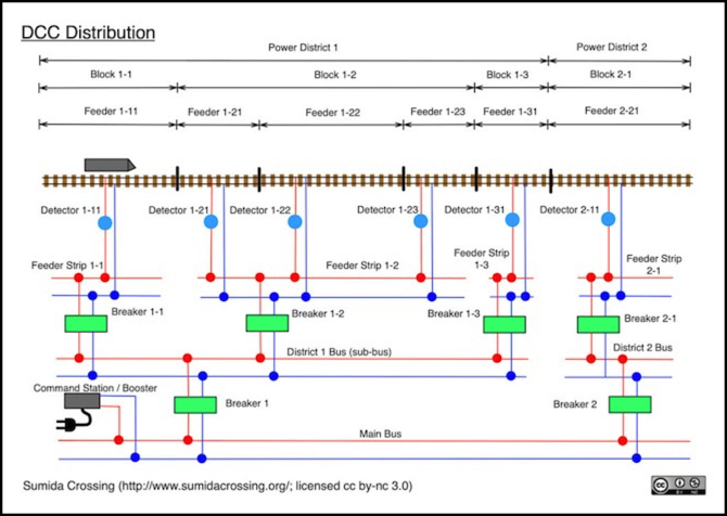
The above diagram shows a layout with multiple power districts, two shown, each subdivided into blocks, with each block having one or more track feeders. The track feeders connect to block terminal strips. The block occupancy detectors can be placed as shown, to enable detecting trains approaching the end of a block, or they could be placed between the sub-bus and block feeder strips if all that is of interest is knowing if the block is occupied.
The feeder terminal strips themselves connect to the district power bus, which is a track bus limited to that district. One set of circuit breakers is placed on these connections. These breakers would be set to perhaps 1 or 2 Amps, to protect trains in one block from shorts caused by trains in another block. Each district bus is connected to a main bus, fed by a booster (or command station), and a second layer of circuit breakers is used to connect the district busses to the main bus. These would be set to a higher level, adequate to handle all trains in the district, perhaps 4 or 5 Amps. If there was more than one booster in use, each would have its own Main Bus.
You don’t really need both layers of circuit breakers. On a small layout, the feeder-strip breakers could be omitted, and the district breakers could be set to a smaller trip current. The benefit of the two layer approach is that a very high-current booster (such as 10 Amps) could be used, while limiting current in the district bus to 4 or 5 Amps, which allows lower-gauge wire to be used with electronics, without any fire risk in a short. In open air, the difference between 5 and 10 Amps is the difference between a minimum wire size of 22 or 20 gauge, but if you want to ensure wire temperatures stay below 75C (due to scenery materials or similar close to the wire), the choice becomes 20ga vs 16ga.
The following diagram shows a more realistic design:
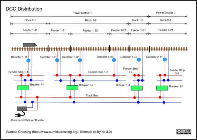
In the diagram above, the booster feeds the track bus directly (the track bus could still be subdivided for multiple boosters). Each block has a feeder strip fed by a circuit breaker. These would be set to allow for the number of trains that could occupy the block, perhaps 1 or 2 Amps. As before, detectors could be located on either side of the feeder strips, either as shown here for fine-grained detection, or with the circuit breakers for block-level detection. Here there’s no difference between the power district and the block, except that if you had multiple boosters, you would break the track bus between the two districts, and attach the second booster to the track bus associated with Power District 2.
Auto-Reversers
An auto-reverser is a special type of circuit breaker. Some circuit breakers can be changed to an auto-reverser with a jumper setting. But keep in mind that an auto-reverser is not also acting as a short-protector, so you should still have one of those, at a higher setting, closer to the power supply. The use of auto-reversers is described on my DCC Layout Wiring page (at the bottom).
When an auto-reverser detects a short, it doesn’t turn off its output, it swaps the polarity of the two rails. This is used on reversing loops, wyes, and other places where the left rail curves around and becomes the right rail at a switch. A train crossing that junction will cause a short across the insulating rail joiner at the switch. When a train enters the loop, polarity will be set for that (which may require a reversal), when it exits, the polarity set on entry will be reversed.
Auto-reversers need to be connected to the rails both inside and outside the loop (i.e., on either side of the switch (or switches for a wye) that they are protecting. Often this is done by ensuring that their input is wired to the feeders outside the curved segment, and their output to the curved segment. So they have to be placed with the protected track, unless you want to run a couple of very long feeders, which generally isn’t a good idea.
A specialized form of auto-reverser is used to control polarity of just one output. This is used to reverse polarity of turnout frogs, to allow use of powered frogs without an A/B switch connected to the turnout motor or control.
Circuit Breaker Sizing
Smaller is better, but too small can be a problem. There’s a balance to be struck here, and no single perfect answer. What your layout needs will depend on the trains you run, and the trains you might run in the future (and that can be very hard to predict). If you make the breaker settings large, there is more risk of damage before they trip, and they might miss some problems. If you make them small, they may trip when there’s no problem.
By definition, a DCC power supply provides power to run more than one train, often dozens. An individual locomotive without a load may draw less than a tenth of an Amp (100 milliamps). But the important feature is the worst-case, which you should already know if you install your own decoders: the stall current of the locomotive. This peak current is what will be drawn (very briefly) when the locomotive starts, and for a longer period if it gets stuck and the motor can’t turn at all for some reason. Something in between minimum current and stall current will be drawn when the locomotive is pulling a load, and that will vary with the load (e.g., going uphill is more load than level track, requires more power, and draws more current).
Stall currents for N-scale locomotives are typically (but not always) under 1.0 Amps. Stall currents for HO could be higher, but probably don’t exceed 2.0 Amps except on very powerful locomotives.
And you could size the breaker to have a lower trip point, since a stalled locomotive might damage itself anyway, and the start-up peak may be brief enough to avoid tripping the breaker. Some experimentation would be warranted. And, just because you largest locomotive draws 1.4 Amps today, that doesn’t mean that you won’t own one next year that draws 1.8 Amps.
Also, if the train normally runs at a certain level, you don’t want the circuit breaker trip current set too close to that, both because it might accidentally trip due to a minor problem (increased load as a train goes through a crossover, for example) or because it might delay recognition of a short (sometimes the rate and amount of current change in a short is what is being detected).
Still, if you know the stall current of all of your locomotives, it’s a good guide for minimum circuit breaker size to avoid problems, and a starting point.
Also consider the design of the DCC decoders you use: do they have power protection? Sound? As discussed in the Unnecessary Trip or Reset Failure subsection above, those can demand extra “inrush current” and you need to budget for that.
But note that if you are planning for two or more trains in the area affected by one circuit breaker, you don’t need to add the worst case numbers. The normal maximum would be the worst case of one, plus “typical” values for the others. Exactly what “typical” means is hard to say in advance, although you could measure it (with an RRampMeter or similar DCC current meter).
Trains aren’t the only things powered by DCC. If you use track-powered DCC accessories (such as turnout controls) you have to consider any of those within the area controlled by the breaker. If they draw power from the main DCC bus (rather than from any wiring to the track), then you can ignore them, except for any breaker you put on the bus.
Finally, locomotives aren’t the only part of a train that draws power. Lighted passenger cars are the obvious case, but you could also have accessories (e.g., active couplers, working boxcar doors, etc). You need to factor their power needs into your power budget.
For passenger cars, LED lighting can draw less than 10 milliamps per car (fairly common for N-scale), but could easily draw tens of mA with brighter or multiple LEDs. Bulb lighting, more typical of older models, can draw 60 milliamps per bulb, and in HO you might have multiple bulbs per car. Bulb lighting can be problematic on DCC anyway, due to heat; they were designed to run on DC, with typical operating voltages around 7V, and DCC will usually be twice that, and produce twice the heat. An HO 8-car passenger train with two bulbs per car could easily add a full Amp to the power requirements, just for lighting, but rather than size for that, you might want to consider replacing those bulbs with LEDs to reduce heat.
So there’s no perfect size. If you run only freight without sound, a 1.0 Amp breaker is probably sufficient, even in HO, unless you have older and very inefficient motors in some of your models. With sound, protection and passenger-car lighting, 1.0 Amps is probably too light even for N-scale (but 2.0 is probably fine) and HO could easily need 3.0 or more Amps.
And don’t forget to factor in the power supply. Setting your circuit breaker to 3.0 Amps when used with an older 2.5 Amp Zephyr would likely prevent it from actually detecting any problems. You might find that a smaller supply like that, while fine for running several fully-loaded HO trains, just doesn’t have enough headroom to also handle additional circuit breakers.
Some Common DCC Circuit Breakers
This is not intended to be an exhaustive list, just a sampling of the more popular models presently available, along with some representatives of alternate approaches, to provide a guide for what kind of features are available and their approximate cost.
Many manufacturers sell models with multiple circuit breakers per board. This reduces both the manufacturing cost, and distribution/retail additions to the cost, so the cost per breaker will generally be lower. But you have to contrast that with how you’ll use them. If you only need two circuit breakers in an area, then you’ll either need to run long wires to use an additional ones (which can cause problems as discussed above) or you’ll be wasting that capacity, making the effective cost per breaker much higher.
Note that simpler circuit breakers, particularly of older design, may be more prone to problems from sound-decoder inrush currents.
DCC Specialties: OnGuard (OG-CB)
This is a simple, fixed, 4.0 Amp circuit breaker. It’s a good example of a minimalist design for a solid-state circuit breaker. It is suitable for larger power districts (or larger trains than typical HO). This is an older design, no longer featured on the manufacturer’s website (in 2017) as far as I can tell, but still available from retailers.
Typical cost is US$25.
DCC Specialties: PowerShield X (PSX)
This is a family of several different models, including basic circuit breakers with one to four breakers per circuit board, and other models with auto-reversers and turnout controls. These are jumper-settable to 1.27, 3.81, 6.35 and 8.89 Amps (but see below for more). The first two settings are reasonable values for typical N and HO requirements, but may not serve all possible cases. This is perhaps the most popular model of circuit breaker, at least judging from online posts, but the functionality comes at a cost.
These also have a “Weak System Boost” feature that changes how short-detection is done, to make it more reliable with low-power DCC supplies (such as the Zephyr or NCE Power Cab).
And they can optionally be configured as DCC Accessories, allowing remote control to turn off track power. And, if this is used, the trip current can be set via software, which allows for 14 additional trip currents beyond the four listed above, starting with 2.54, 5.08, and 7.62 Amps. Most of these aren’t going to be useful unless you are working in very large scales (if then), but the first two could be useful, as 2.54 is a good intermediate value for smaller HO requirements, and 5.08 could be useful as a district-level protection when 8.0 Amp or larger power supplies are used.
The larger models are really just multiple of the single circuit breaker laid out side-by-side on a board that is two or four times as large. There’s little advantage (other than a couple of dollars in savings) in buying those versus more of the single-breaker size.
Typical prices start at US$40 for a single circuit breaker or around US$135 for the 4-breaker model (about US$34 per breaker).
Digitrax: PM42
This is a set of four circuit breakers on one board. The PM42 uses relays to switch track current. Unlike most others it does not come with screw terminals, but requires soldering wires to a card-connector (or directly to the circuit breaker).
Trip current is set in software. Possible values are: 1.5, 3.0, 4.5, 6.0, 7.5, 9.0, 10.5 and 12.0 Amps.
Typical prices are around US$65, or just over US$16 per breaker.
Litchfield Station: TVD-CFJ003U
This is a circuit breaker variant of their popular “Frog Juicer” (which is a simple auto-reverser for switch frogs), with screw-terminal connectors.
It has jumper-settable trip currents of 2.0 and 4.0 amps and can be used with up to 10 Amp power supplies.
This appears to be only available from the manufacturer. List price is US$25.
MRC: 1527
This is a single 5.0 Amp circuit breaker, relay based, with pre-connected wires (to be connected to track and supply). It’s intended as a power-district breaker for 8.0 Amp and larger power supplies.
Typical price: US$35.
NCE: EB1
This is a popular model (perhaps second to the PSX). It is a single circuit breaker, there are no models with multiple per board. Trip currents are jumper-settable to 2.5, 3.5, 4.0, 5.0, 6.0. 7.0, 7.5 and 8.0 Amps. Although it lacks the lower-value setting of the PSX, 2.5 Amps is not unreasonably high for N-scale trains, particularly if you have or plan multiple units with sound.
It can be configured as a DCC Accessory, but this does not allow for control over power to the track or trip current setting (at least not as I read the manual).
Typical prices are around US$24.
TrainModules: TM-28868
This is a simple, fixed current, solid-state breaker with a 2.7 Amp trip current.
List price: US$28 (converted from Euros). This appears to be only available from the manufacturer.
