


Subway Design
Did I mention the subway? Tōkyō has more than a dozen subway lines, operated by two different companies. Many of these use the same track gauge and power type (overhead 1,500 volt DC) as the narrow-gauge commuter lines, and offer run-through service to suburban trains that need to reach downtown destinations, although typically special trains will be used that fit the slightly narrower clearances, and the shorter platforms, of the subway stations. However, some subway lines use different gauges or third-rail power.
I can’t take credit for the idea of a model railroad with a subway, but once I’d heard of someone else who made one, it made perfect sense as a way to add some complexity to operations, and some visual elements lacking from most model railroads. And it fits in perfectly with my idea of an “urban railroad” layout.
My subway draws inspiration from the Tōkyō Metro Marunouchi Line subway (one of the odd standard-gauge, third-rail systems) which crosses the Kanda river near Ochanomizu station. However, I’ve merged that with the idea of a same-gauge, overhead-power subway that offers run-through service, to provide more operational interest.
The addition of a subway with run-through services gives me two more “commuter” stations, for a total of four, in the same space, at the cost of not being able to see the trains for most of their time underground.
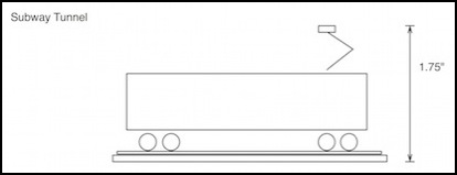
The first question to answer is: how big does the tunnel need to be? That’s a fairly simple question to answer. It should be high enough for a single-level commuter car to fit (I wouldn’t expect a double-decker to be used in subway run-through service), and wide enough for double track. That’s at least 2.5 inches on a straight, plus a bit to make it easy to get the track in and out. On a curve you need to allow room for overhang, but on commuter cars, that’s not much. I ended up using about 3" on both curves and straights as my inside tunnel width.
The basic height needed is that of a single-level car (with fully raised pantographs) plus unitrack. That’s only 1.75”. With a little extra for safety, and 1/8” for cork to deaden noise from the cars, it will fit in the two inches I have available using the lowest possible “ground” level. For more about the tunnel cover, see the Subway Cover page.
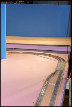
Construction of the subway track, using unitrack went well. The following photos show various stages of the initial planning, laying the track out on the first layer of insulation foam to ensure I knew where the tunnel walls would go, and allowing me to test for smoothness of operation and clearance. This kind of "prototyping" with Unitrack is an important aspect of my approach to the design of this layout.
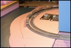
Initial track placement checking (left) and final Riverside Station alignment (R) with cork roadbed.
In the photos above, the subway track is show laid on the lower layer of foam, which elevates it above the “river” surface enough for a bridge. More foam will be added surrounding these tracks, which will be entirely underground except where crossing the river. The long straight stretch in the upper right is the location of the Riverside (aka “Kawate”) subway station platforms, hence the wider separation of tracks.
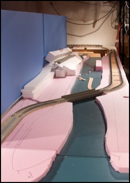
Another view of the Riverside track (L) and the end of the Urban Station track (R) nearest the River Crossing scene.
The above photos also show the final track placement, this time for the two stations (the one on the right located at “ground level” under the viaducts. The ground rises towards the river at the top of the right-hand photo and the track becomes underground for the curve seen in the top, left, photo.
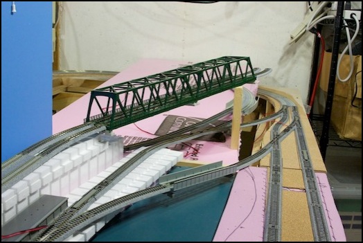
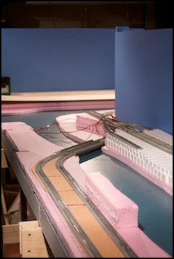
The subway with the revised connection to the Riverside Station tracks. This will allow trains to inter-run between the subway and the inner (aka “Commuter”) loop of the layout, which is something found in several prototype railroads of Tōkyō. Again the foam is just loosely placed while I work out track position, clearance, and other design issues.
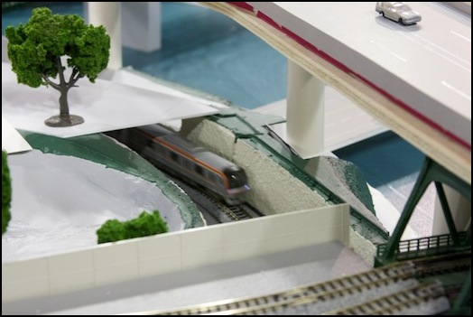
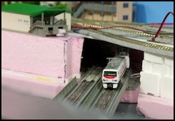
June 2010: A subway train runs beneath the park at the edge of the large river. The roof of the tunnel has been removed to show the subway, normally this section would be hidden from view. This is what the tunnel looked like during the "first run" (first day of operation) of the subway, after the foam had been painted (with interior latex paint) but the cover was still bare white styrene. There's video of the First Run on my Movies page, although it doesn't include this view.
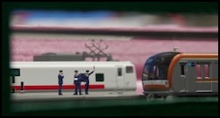
Two more "first run" images. On the left, the trains waiting to depart in the RiversideSubway Station, which shows (roughly) how the view through the side viewing windows will look. Part of the reason I did this was to ensure the window size and placement was going to work. On the right, the inspection train (my Micro Ace model of JR East’s “East-i E” track inspection EMU) emerges from the tunnel and crosses the bridge over the narrow river.
For more about the Subway, see the Subway Scene page or the Subway Photo Album.
