


Track Standards for Straight Track
The standards by which track is constructed are well-defined by the usual standards bodies, but there is still significant variation depending on the era and type of railroad modeled, as well as the modeler’s desire to accurately portray prototype usage versus making it easier to build and operate the models. Prototype railroads themselves have standards, but these vary from company to company as well as over time. The “look” of a 19th-century narrow-gauge rural line will be very different from that of a 21st-century urban commuter railroad.
And when using parts from manufacturers, it is important to be aware that these may differ from the standards, and from track manufactured by other companies (or even by the same company!), so it’s important to investigate the specific track you plan to use, and determine what dimensions the manufacturer has used, particularly if you plan to use track from two different manufacturers together. This is particularly true with pre-assembled crossover (single or double) switches, where the manufacturer assumes some standard spacing between parallel lines, which varies considerably.
This page is going to set out some basic information about track standards, and in particular clearances and parallel-track spacings, with a focus on my area of interest: 21st-century Japanese passenger railroads in N-scale. First I’ll cover prototype practice, then the various existing modeling standards, and finally the product lines of some common manufacturers in N scale.
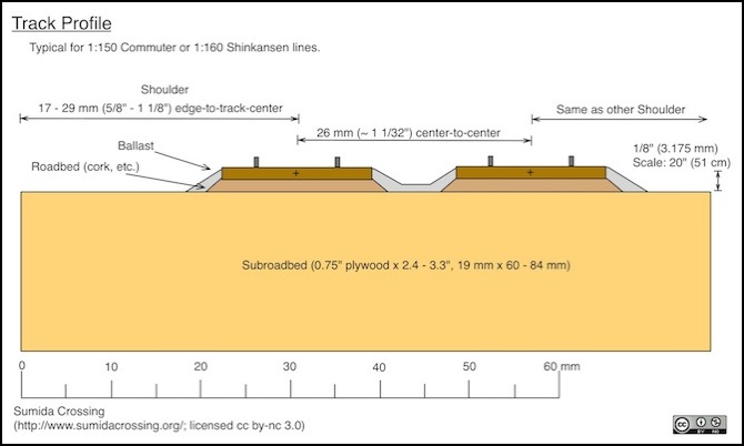
Here’s a typical profile of prototypical Japanese N-scale double-track done to standard dimensions. I’ll cover just what those are below, and I should note that there’s some guesswork involved and some indication that urban tracks occupy somewhat less space.
Prototypes
The railroads we model have their own standards. While directly trying to model these in scale is often not the correct approach, it’s worthwhile to know how they build their tracks, so ours can at least approximate them. Although I’m modeling Japanese railroads, information on the trackwork of these is a bit hard to come by in English, so I’m going to cover American and European prototype track as well. Japan operates in very space-constrained environments, but so too do some European lines. American railroads tend to occupy more space, at least outside of major urban areas where their track is constrained by space allotments dating to the nineteenth century.
Roadbed
On the prototype, “roadbed” refers to the relatively level ground below the ballast (it’s actually graded to slope down slightly from the mid-point to each edge, but this isn’t normally visible), which is what modelers describe as subroadbed. This can be variable in width, and sometimes has space on one side for a service road parallel to the tracks. However except in very space-constrained locations, a minimum clearance larger than the size of the railway vehicles is typically provided. Note that the prepared roadbed is often smaller than the overall “right of way” owned by the railroad, as there’s usually additional space for telegraph poles, future expansion, or the slopes of fills or cuts. The right of way may be 100’ (30 m) or more in width.
One standard for a North American railroad that I’ve seen provided an overall width of 30’ (just under 10 m) for single or double track roadbed, leaving about 7.5’ clear on each side of a double-track line.
One purpose of the extra width between trains is to allow the downward force from trains, transmitted to the ground through the ballast, to dissipate into the ground without shoving it to the side. Thus the width will depend on both the quality of the soil and the weight of trains being operated. For high-speed rail, space must also be provided for the air displaced by a train to move aside, although this could be reduced if there is open air beyond a fenced border.
Beyond the edges of this flat space, the ground will typically fall away to promote drainage and keep the track’s roadbed and ballast dry. If the track is in a cut or on a long stretch of very level ground, ditches will be dug on each side for drainage.
I don’t have a complete description for typical roadbed profile for Japanese commuter lines, but in constrained spaces a minimum of 2.75m to the side of the track is required unless this can be reduced without affecting operations or the ability of track workers to take shelter (see MLITT standards cited in the References section, page 25). However it’s not clear (to me), if this space is measured from the edge of the train’s loading gauge, or the ballast, or what. For Shinkansen, the standards call for a space on the side of the track of 3.0m minimum, with 3.5m provided on at least one side where workers may take shelter from passing trains. On bridges, viaducts and tunnels, shelters can be provided by wider sections (“sheltering bays”) located every 50m.
Assuming the space is measured from the loading gauge (i.e., the one-half width of the widest car from track centerline), for a typical commuter line this would require a clearance of 4.225m from track centerline, or 28 mm in 1:150 scale. For a Shinkansen, this works out to 4.7 m from track centerline, or 29 mm in 1:160 scale. Additional space would be required on at least the Shinkansen line to provide for sheltering track workers.
A more conservative space estimate can be had if you assume that the space is measured from the track centerline. Then the overall width of the line becomes 2x 2.75 + 3.55 = 9.05 m (29.7’). From some measurements I made, although of dubious accuracy since I was using consumer-grade mapping tools, this seems like it might be a more reasonable minimum.
On a curve this is further widened by an amount related to the cant (superelevation) of the curve, probably reflecting the need for more space (although they apparently require the same widening on both inside and outside of curves). However, the maximum amount of widening (for a Shinkansen) is just 0.55 m (22”), or about 3 mm on a model, so this aspect can be ignored for modeling purposes. On a model, other factors will affect curve widening, and those are discussed on the Curves page in this section, as well as in the Modeling Standards section below.
Thus, as shown in the diagram above, a typical N-scale double track would have a roadbed 83-84 mm (3 5/16 inches) in overall width for either kind of use (we’ll get to the track spacing further down the page). When using plywood as the subroadbed, this would be the maximum width it should be cut to, in order to allow the scenery to fall away on either side. On curves, if the two tracks are placed further apart, the roadbed should be widened by an equivalent amount to maintain the same edge clearance.
Note: I made some measurements using Google Earth of Tokyo-area tracks. While I’m not certain of its accuracy, measurements of two-track roadways ranged from 8.0 m to 9.6 m (26.2 to 31.5 feet), but were generally in the range of 8.2 m to 9.0 m (26.9 to 29.5 feet). I also measured one Shinkansen viaduct at 10.3m (33.8’) adjacent to a commuter viaduct at 9.0m (29.5’).
And, on the north side of Tokyo I measured the ten-track roadway as an overall width of 43.0m (141’), or and average of 8.6m (28.2’) per pair. That’s considerably tighter than my reading of the MLITT standards would suggest is allowed, and may indicate that the space to the side is measured from track centerline.
This means that it’s reasonable to expect a Shinkansen line to be about 10% wider than a commuter line. However, if the measurements are accurate, it suggests that urban construction doesn’t always hold to the MLITT minimums, even assuming the narrower estimate of what those are.
Additionally I found a commuter-line storage yard to have tracks about 3.8m (12.5’) apart. That works out to a scale 25.3 mm, assuming the measurements are accurate.
Ballast and Ties
The gravel around and under conventional ties (aka “sleepers”, since Japanese railroads often use British terminology in English translations) provides both support and water drainage for the ties, the latter of which is important both in preventing rot and increasing electrical resistance between the rails so detection circuits will work reliably.
In typical European mainline track, ballast is 3.4m (11’ 3.8”) wide across the top in most situations, and 30 - 35 cm (12-14”) deep below the ties. In 1:160 scale this equates to 21.25 mm wide and 2.2 mm under the ties. I’ve seen similar standards for newer British lines. Normal modeling roadbed occupies the space under the ties filled by ballast, and the typical 1/8” roadbed is 3.2 mm thick, so it’s already about 50% thicker than heavy mainline ballast would be.
On smaller lines the width stays about the same, but the amount of ballast is reduced to around 20-25 cm (8-9 inches). However lighter rail is also used, so this tends to make sidings and branch lines look ever lower when placed near mainline track.
When concrete-slab construction is used, there is no ballast, with the rail attached directly to square or rectangular concrete blocks about the width of ordinary railroad ties. Japanese lines also use “solid bed” track where a tie is used, but it is set into a padded space in a long concrete slab with no ballast, however this form is as yet uncommon. In modeling modern Shinkansen, use of slab track would be most accurate, although if I don’t want to scratch-build the track, use of concrete-tie track isn’t completely inappropriate, although mostly present on older construction.
While example dimensions for Japan haven’t yet turned up, I did find a report on slab track used in the Czech Republic that had slabs 2.8 m wide and 24 cm thick below the rail, set on a larger base of 3.4 m width and 30 cm thickness.
Tie spacing is variable, and depends on the class of line and the material used for the tie. A common European dimension is 60 cm (23.5”) between tie centers on mainline track. In North America closer spacing is typical of mainline track, to support heavier rolling stock, spacings around 20” (51 cm) are common.
Track Spacing
This is variable. In Europe, typical spacings are around 3.6 to 4.8 m (11’ 10” to 15’ 9”). In Japanese N (1:150 scale), this works out to 24-32 mm, while in Shinkansen (1:160 N) it works out to 22.5-30 mm.
High-speed rail lines are usually spaced wider apart than conventional tracks, to allow space between passing trains for the air displaced by the front of the train to move, cushioning the sideways force against each train. European high-speed rail lines mostly use a spacing on straight track of 4.5 m (14’ 0.2”) for 350 kph track and smaller spacings on some lines at lower speeds. Japan, however, uses a standard spacing of 4.3 m (14’ 1.3”). This equates to 26.9 mm in Shinkansen (1:160) N-scale.
Under Japanese law, the minimum track spacing is the width of the widest car operated plus 600 mm for lines operated at less than 160 kph. Thus for narrow-gauge commuter stock using typical 2.95 m wide cars, the minimum spacing would be 3,550 mm, or 11’ 7.7” between track centers. In Japanese N-scale (1:150) this would be 23.6 mm, or slightly less than the typical minimum spacing used on models. This can be narrowed slightly (to +0.4 m rather than +0.6 m) if cars do not have openable windows.
At Shinkansen speeds up to 300 kph, minimum spacing is the width of the car plus 0.8 m. Typical Shinkansen cars are 3.38 m wide, so this sets minimum spacing at 4.18 m (13’ 8.5”). In Shinkansen (1:160) N-scale, this equates to 26.125 mm.
The Modeling Standards
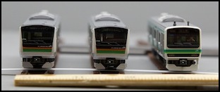
The standards bodies have advice here. While there are variations, these work out to around four distinct spacings between track centers, seen in the photos below (read below on this page for the details).
The closest spacing, just over one inch (26 mm to be precise) is fairly prototypical for mainline track. In some cases real mainlines would be even more closely spaced, but this is probably the minimum for reliable operation on straight track. European standards actually recommend this spacing for a variety of conditions, and the NMRA recommends it for normal straight track.
Somewhat wider spacing, 29 mm or 1 9/64”, is needed on relatively sharp (368 mm or 14.5”) curves using short rolling stock. If you put long cars around such curves, you’d need even wider spacing, but it wouldn’t look very good. This could also work on a mainline and still look quite good. The European modeling standards recommend about this spacing for station tracks, where crew would need to walk between trains for inspections or other reasons. The NMRA recommends this for yard track (well, 30 mm, but close enough), although I’m not sure why.
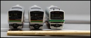
26 mm (1 1/32”) and 29 mm (1 9/64”) Spacing
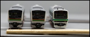
As things get further apart, they don’t look quite as good. A spacing of 33 mm (1 19/64”) is about what’s needed on a fairly broad curve, 546 mm or 21.5”, for long passenger stock. You’d need an even broader curve to bring the cars closer together. This is also Kato’s standard spacing for their double-track. It’s okay, but I’ve always thought it looked a bit too wide.
And finally, the widest spacing of 38 mm (1.5”) is standard on modular railroads, and it’s close to the 37 mm used by Tomix FineTrack. It’s also a good spacing for a yard where you’d want a “five fingered crane” to be able to lift a car off a track without disturbing the adjacent one. However, it’s obvious from the photos that at this size, three tracks occupy space that could be filled by four, and I don’t find it at all prototypical.
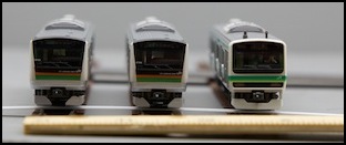
33 mm (1 19/64”) and 38 mm (1 1/2”) Spacing
NMRA
The NMRA lays out a number of standards. They are currently re-working their website, so if there are problems with any of the links below, try the main standards page or go to NMRA.org and look for a Standards and Practices link.
S-3 Trackwork has been subdivided into three documents: S3-1 Trackwork Proto Scales (PDF), S3-2 Trackwork Standard Scales or Scale Track, Standard Scale (PDF), and S3-3 Trackwork Hi-Rail Scales or Standards, Deep Flanges for Guarded Tracks (PDF). I’ll focus on the Standard Scale version, however this really only discusses track and guardrail spacing, and unless I’m handlaying track, I don’t need this information.
S-7 Clearances (PDF) defines the space occupied by a rail vehicle in three eras: Old Time (pre-1920), Classic (1920-1983), and Modern (1983+) for a number of scales. There is also a special standard for light rail and other “traction” lines, S-6 Interurban Clearance and Track Centers (PDF). My focus will be on Modern era clearances. There is also a recommended spacing for yards, supposedly to make lifting cars by hand easier, except that the number is simply the standard clearance spacing.
On curves, spacing between parallel tracks is typically wider than on straight track to allow the for the ends and middles of cars to swing away from the track centerline. This is most important with long cars and/or sharp curves.
S-8 Track Centers (PDF) describes the spacing between adjacent parallel and curved tracks. This is given for three classes of trains: very long steam locomotives and passenger cars (Class Ia), long steam locomotives and six-wheel truck diesels (Class I), and smaller locomotives including four-wheel truck diesels (Class II), and the spacing varies by the degree of curve.
In their Recommended Practices series of documents, RP-10, Trackage General (PDF) provides an index to a variety of topics, with some general comments, while RP-11, Curvature and Rolling Stock (PDF) provides information on curve radii (which is covered on my Curved Track page).
Finally, in their Module Standards series there is guidance on separation of parallel tracks on multi-track lines. MS-1.0, Module Standards, Standard Gauges (PDF) covers most railroading, while there are separate ones for narrow-gauge, MS-1.1 Module Standards, Narrow Gauge (PDF), and light-rail lines, MS-1.2 Traction/Overhead Standards, Modules (PDF).
The basics of these are the following:
Vehicle Width (straight): 1 3/8” (34 mm)
Vehicle Height: 1 23/32” (44 mm)
Yard Straight-Track Spacing: 1 3/16” (30.2 mm)
Straight-Track Spacing: 1 1/32” (26.2 mm) or for modules 1.5” (38.1 mm)
Curved-Track Spacing:
- 1.5” (38.1 mm) for modules (all curves)
- 1 11/32” (34.1 mm) for 21.5” curves (546 mm), Class Ia (long passenger)
- 1 7/32” (30.1 mm) for 17” curves (432 mm), Class I (six-wheel diesel)
- 1 5/32” (29.4 mm) for 14.5” curves (368 mm), Class II (four-wheel diesel)
Note: Track spacing is measured center-to-center (or, more easily, outside rail of one track to inside rail of the other).
The first two of these are the basic loading gauge, although a more complex shape is defined in S-7 and is the basis for the standard clearance gauge.
From this you can see that module standards are overly large, while the other standards provide a somewhat tighter spacing, with wider spacing in curves than on straight Track.
MOROP
The European standards body defines numbers similar to those of the NMRA in German and French, but not English (not yet, anyway). The relevant document is NEM-112, Track Distances, and the data in it is in tabular form, so in the second table just cross-reference your scale and vehicle class (across the top) to the radius in millimeters (down the side) to get track spacing on curves. The first table is track spacing on straight track, and it’s pretty easy to figure out even without a translator.
They provide for three vehicle classes:
A: 20.0 m length with 14.0 m “box pivot” length.
B: 24.2 m length with 17.2 m “box pivot” length.
C: 27.2 m length with 19.5 m “box pivot” length.
I think “box pivot” is distance between truck centers, but I had to read this in machine-translated form, and it wasn’t entirely clear.
Minimum Spacing (mainline): 25 mm
Minimum Spacing (station): 28 mm
Curved-Track Spacing:
- 550 mm radius, class C: 26 mm
- 450 mm radius, class B: 26 mm
- 350 mm radius, class A: 26 mm
This provides for closer spacing than the NMRA numbers, but not by a large margin.
Manufacturers
Now, of course, manufacturers don’t always follow standards. You might think that with flex track you don’t need to care about what the manufacturer does, but unless you plan to build your own switches, crossovers and slip-switches, their standard spacing is going to matter on straight track and in yards. Kato, for example, uses 33 mm spacing on their Unitrack double-track, but 25 mm on their UniTram. However they also use other spacings, such as 49.5 mm for sidings. Tomix by comparison normally uses 37 mm spacing for parallel tracks.
Peco seems to follow the NEM standard, with spacing on their double-crossover of about 26 mm. This is also the spacing you get from placing two of their normal switches end-to-end to form a single crossover. In Japanese N-scale, this works out to 3.9 meters (12’ 9.5”). In 1:160 (Shinkansen or normal N-scale) it’s 4.16m (13’ 7.78”). So you can see that this is a close approximation of real European track spacings. It is also a very close match to standard Shinkansen track spacing.
Even if you hand-lay, this can be an issue. The Fast Tracks jig for an N-scale crossover is documented as using a 27.7 mm track spacing. That’s a rather odd number, as the only standard it sort-of matches is the MOROP station track spacing of 28 mm.
Loading Gauge
The “loading gauge” (sometimes spelled “gage” in North American English) is the clearance around a track centerline within which trains move. This has to be kept clear of obstructions such as passenger platforms, trees, and utility poles. In modeling this is often referred to as the “clearance” around the train (e.g., the NMRA Clearance Gauge shows a typical mid-20th Century North American track clearance outline).
In Europe, there are a variety of loading gauges, but the largest (UIC C) requires, per Wikipedia, 3.15 m (10’ 4”) width and 4.65 m (15’ 3”) overall height. In North America there are also a variety of loading gauges, with the largest at 10’ 8” (3.25 m) width and 20’ 2” (6.25 m) height. In both cases, many older lines are constructed to smaller dimensions.
The same wikipedia page notes that Japanese Shinkansen lines use a loading gauge of 3.4m (11’ 1.85”) wide and 4.5 m (14’ 9.2”) height. I haven’t been able to confirm that independently, but the loading gauge is just over the size of typical Shinkansen cars, so it is likely correct. That equates to a width (in 1:160th scale) of 22 mm and a height of 28mm.
Modeling Standards
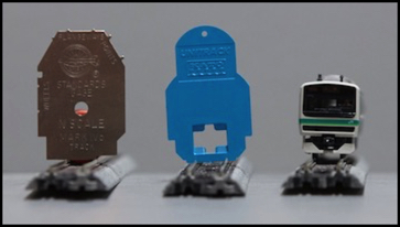
Both the NMRA and Kato produce “clearance gauges” designed to allow modelers to quickly check for clearance issues in the loading gauge. They’re not identical though, as they’re dealing with models of two very different prototypes (and Kato has to deal with both 1:150 and 1:160 scale models).
Note: the Kato gauge comes in several of their sets, but can also be purchased separately with a Terminal Unijoiner pair (20-818) for about US$5. The NMRA gauge can be purchased from their online store (non-member price US$12).
The NMRA gauge (defined in their S-7 standard) is 29mm wide and 42mm high (from rail top). The Kato gauge is just under 28mm wide, but narrows at the top to 20mm, however it’s taller, at 48mm in the center. As the photo below shows, this is clearly to allow room for roof-mounted pantographs, whereas the NMRA gauge is intended to allow double-stack containers and other large-format freight cars, which have more rectangular profiles.
Modeling Japan
My take away is that while i could use different track spacings for Shinkansen and commuter, the recommended minimum of 26 mm (and the standard size enforced if I use Peco crossovers) is about right for the minimum spacing allowed the prototype. This means I should be able to work with that spacing and it will look very close to the prototype indeed. Alternatively I could use 28 mm and be right for hand-built crossovers (which I might need if I end up hand-laying slab track in some places). Or I could use either and have the tracks shift slightly when they approach a crossover.
I may need to do some testing to see how well this works in practice with some of my models that have tilting mechanisms, causing them to hang over further on a curve (like the prototype) than a non-tilting car. I may need to broaden curve spacing even though per the MOROP standards it would appear to not be required on the curves I contemplate using. Even if it doesn’t affect operation, slightly broader spacing on curves may look better also, and that’s something to consider.
The diagram at the top of the page assumes the 26 mm spacing will work on straight track, and further allows 29 mm on each side before the ground falls away (for a fill, or to a drainage ditch in a cutting). This is likely to be my standard double-track profile except where conditions require something else. But for modeling dense urban trackage, closer spacing may be desirable, if clearances permit.
For clearance, I’ll use 50mm (2”) in overall height above railhead as my target (which allows for some measurement error). To that I’ll need to add a bit over 3mm (1/8”) for roadbed, plus the height of rail and ties, which is roughly the same. Thus I’m looking at something around 56mm (2.2” or 2 3/16”) above the subroadbed. This does not allow for a double-layer of cork roadbed, which I’ve seen recommended as a way to reduce wheel noise. I could probably add that if desired without causing problems as all of these numbers are somewhat conservative, but I might round up to 6 cm just to be safe.
References:
The Mechanism of Railway Tracks, Shigeru Miura, Hideyuki Takai, Masao Uchida and Yasuto Fukada, JRTR Issue 15, March 1998.
A good general overview of Japanese rail track structure, with a focus on Shinkansen design.
Railway Structures 2, Track and Environment (presentation, PDF)
- This provides information on Czech Republic railway design (in English)
Railway Track Engineering, by J. S. Mundrey (Google Books)
- This provides information on prototype track spacings.
Technical Regulatory Standards of Japanese Railways, Railway Bureau, Ministry of Land, Infrastructure, Transport and Tourism (PDF)
- This is an English-language compendium of the Japanese regulations affecting railways. It is based on regulations in effect as of 2006.
