


Typical DC Motors
The modern model train motor is a miracle of engineering, fitting a great deal of complex design into a simple and relatively inexpensive mechanism that is very compact and has a wide range of operating ability, from crawling at prototypical yard speeds to hauling large numbers of cars in a mainline freight. But there is a fair amount of variation in specifics from one motor to the next: what differentiates these, and to what extent does it affect their behavior? This page will survey a number of typical N-scale motors (since that’s where my present modeling interest lies) as well as a couple of HO ones for comparison.
I’ve measured the characteristics of a number of my motors using a regulated 12 Volt bench power supply, to get typical stall currents needed for DCC (I’d size a DCC decoder based on the 18 Volt measure, since some DCC systems can be that high; this is 1.5 times the stall current measured at 12 volts). As a general rule, my Japanese models are under 1 Amp (typically around 750 mA @ 18 Volts), while the 5-pole motors produced for the U.S. can range as high as 1.5 Amps @ 18 Volts.
Another interesting metric is what I’m calling the “minimum DCC frequency”. This isn’t an absolute minimum, but it’s the minimum PWM frequency at which you can be certain that the magnetic field is mostly maintained in the motor’s armature between pulses. As a general rule supersonic decoders will exceed this, producing less heating in the motor and longer life for the brushes, while non-supersonic decoders will not. Calculation of this is simple, assuming you have a meter that measures inductance (an “LCR” meter): first calculate resistance from the stall current (don’t measure it, measured resistances are misleading) R = V/I, where V is the voltage and I is the stall current, in Amps, at that voltage. Next calculate the “time constant” of the motor as T = L / R, where L is the inductance (in Henries) and R is the resistance calculated above. It’s best to use a regulated DC source, not a power pack, to measure the stall current at a precisely known voltage (I measure at 6V and multiply by 2 for 12V and 3 for 18V). The “minimum DCC frequency” is simply the reciprocal of the time constant (1/T).
Actual Motors
I’ve taken apart recent models from a variety of N-scale manufacturers, and they’re all very similar in the design of the motor. There are detail variations, often between models by the same manufacturer. Also, models made for the North American market tend to be five-pole designs, while models made for the domestic Japanese market (which are what I collect) are a mix of three-pole and five-pole designs, but surprisingly the three-pole ones are newer.
Motor dimensions are given in millimeters without the black plastic frame holding the motor. The first dimension is the width from open face to open face, the second is the height, from outside the two magnetic poles (measuring the outside of the metal U-shaped element), and the last is the end-to-end length not counting any protrusions where the shaft bearings are located (flywheels are also not counted, since they aren’t part of the motor).
Kato uses slightly different motors for their Japanese-prototype and North American-prototype models. They have also made changes over the years, although not consistently.
Actually, I’ve measured a couple of these now. In a train, loaded only with the drivetrain (wheels spinning in air) one of my Kato motors runs at 14,000 RPM on a ~13V PWM supply (from a DCC decoder). Disconnected from the train a similar motor from another manufacturer ran at 26,000 RPM at 12V DC. The Kato train uses a 12:1 gear-ratio drivetrain, so 14,000 RPM equated to about 180 scale kph (112 scale mph).
Kato North American Motors
The older “blue box” models made by Kato were not “DCC Ready” in the sense that they could easily be converted to DCC with a lightboard swap (some of the subsequent “green box” models were identical to these, the change in design to be more DCC compatible came after the box color was changed). The motor in both appears to be very similar.
And, while Kato doesn’t seem to mention it themselves, some website stores tout Kato’s North American locomotive models as being “5 pole” designs, and they are. I have three Kato models of North American prototypes: a “green box” SD40, and more recent “blue box” models of an SD80MAC and a GG1. All of these are five-pole motors with straight windings, and all are equipped with dual brass flywheels. This sizes vary slightly, but electrically the motors seem nearly identical.
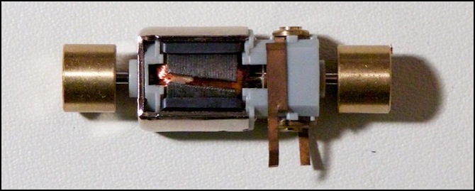
The motor from the SD80MAC is typical. The motor itself (dimensions 9mm x 14mm x 23mm) is held inside a black plastic mounting bracket that snaps around the two bearing hubs at the ends of the motor. The shaft sticks through this, and flywheels are attached to it. Two brass tabs above the brushes have short brass strips, which make contact with the brass strips running along the locomotive body between the trucks.
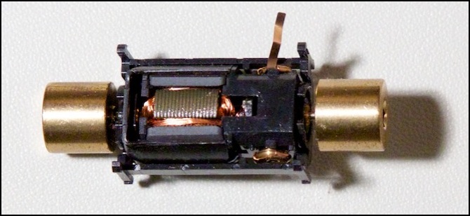
Kato North American “green box” motor (SD80MAC version), five-pole with straight windings
Note: this (the SD80MAC) motor is the one I mentioned above that ran at 26,000 RPM at 12V DC with no load.
The stall current at 12 volts is around 1 Amp (980 mA to be precise), and winding resistance is thus 12.2 ohms, while inductance is 1.336 millihenrys (mH).
Stall current matters when selecting a DCC decoder, and since many DCC systems put put more than 12 volts, a very robust decoder is required for these motors. Most DCC systems put out 15 volts, so a decoder rated for at least 1.25 Amps of stall current would be recommended as a minimum size for these locomotives, and 1.5 Amps (for 18 Volts) might be safer.
Those last two numbers (resistance and inductance) are of interest, as they determine how the motor will react to the PWM output of a DCC decoder. From this I can calculate the minimum DCC frequency as 9.2 kHz.
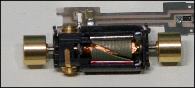
For a second sample, I also measured the motor out of my Kato GG1. This is also a five-pole, straight-wound motor. Dimensions are 9mm x 14mm x 23mm. At first it appeared smaller than the SD80 motor, and of a slightly different design, but this turned out to be the plastic frame holding it, the motor itself had the same dimensions. Electrically, it was nearly identical, with stall current of 775 mA, L=1.3 mH and R=15.5 ohms. That’s not quite identical, but very close. The minimum DCC frequency is 12 kHz.
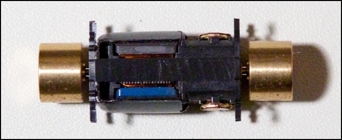
Kato GG1 motor, five-pole, straight-winding, dual flywheels
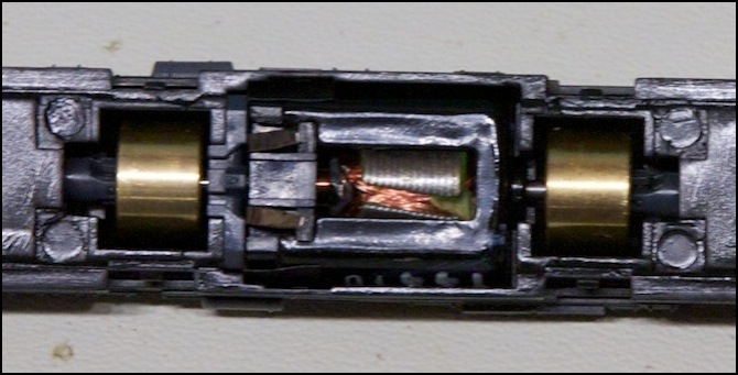
As a comparison, I picked up an old “blue box” SD40 (176-201) in a clearance sale. The motor is outwardly similar to the later model: five-pole, straight-wound, and equipped with large brass flywheels. The dimensions are 9mm x 13mm x 24mm. The model had the older lightboard design, and clearly dates to an earlier period than the SD80MAC model. The stamped metal used on the armature is slightly different, but otherwise it’s identical to the other two North American models. Stall current is 820 mA @ 12 V, R = 14.6 Ohms, L = 1.28 mH. The minimum DCC frequency is 11.4 kHz.
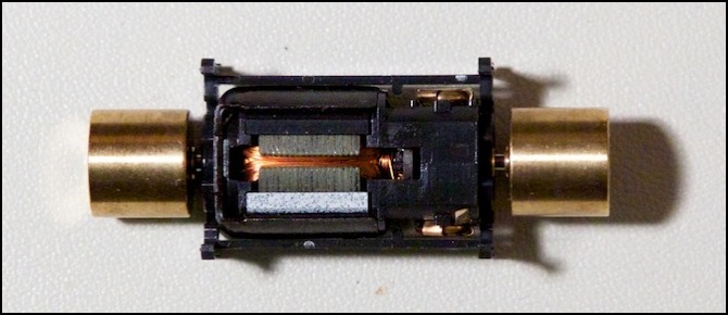
Kato “blue box” SD40 motor, five-pole, straight-wound, with flywheels
It’s interesting that these are all similar to what Kato used to use on their models for the domestic Japanese market, but there they’ve moved to a three-pole design with skewed windings. It’s possible that the North American market is “stuck” with the older designs because of our perception that five poles are better than three. And for all intents and purposes the three motors are identical in specification: stall current around 0.8 Amps @ 12 Volts, and L = 1.3 mH. They’re probably all the same motor, allowing for minor manufacturing variations.
Note: while a 1 Amp DCC decoder would be appropriate on a 15 Volt DCC system, many systems carry higher track voltage. I wouldn’t use less than a 1.2 Amp decoder (safe at 18 Volts) on these, and a 1.5 Amp decoder (safe up to just below 23 volts) would be preferable.
Walthers Life-Like
Kato seems happy using straight-wound motors in all of their models (as we’ll see below, what they do in Japan is slightly different). But it is possible to have both five poles and a skewed armature in an N-scale locomotive. Walthers touts “5-pole, skewed armature” as a feature of their Proto N line of locomotives, and I happen to have one I picked up on sale (I needed a cheap locomotive for some testing I was planning). It really does have a 5-pole, skewed armature motor. The only question is, did they do that purely for marketing purposes? Or do you get an advantage from the design? BTW, the motor and frame design are nearly identical to Kato’s, and Walther’s designs are said to be “clones” of Kato’s split-frame design (I have to wonder if there’s a shared factory or a silent license from Kato involved). So Kato could likely do the exact same thing if they wanted to. The interesting question, to which I don’t have an answer, is why they don’t.
I will point out that the amount of skew on Walthers’ motor is similar to that on the Micro Ace (further down the page), and much less than Katos. In the case of Walthers, that’s likely simply due to the smaller size of each armature lobe due to having five of them. The effect of this in practice is unclear.
Walthers Life-Like “Proto N” locomotive with 5-pole, skewed armature motor
Atlas
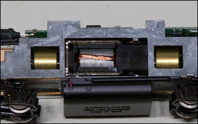
Another common manufacturer is Atlas. I have one of their models as well, a B23 I’ve used in a variety of tests (yet another cheap loco picked up on a clearance sale table so I’d have something to run tests with). The motor is a typical open-frame motor of 9mm x 12mm x 24mm.
This is slightly different from most of the other motors, with gray plastic instead of black. Although it is a five-pole skew-wound motor, the inductance is nearly three times that of the others, L = 3.72 mH, R = 33.3 Ohms. Stall current was just 360 mA at 12V. It also looks similar to the Walthers motor, with a silver magnet connector and the angled windings (at nearly the same angle as Walthers, unlike some of the Japanese models further down the page). The minimum DCC frequency is 8.3 kHz.
On regulated DC I could make it move at about 4.4 V, at which speed it was drawing just 10 mA. Using my Kato power pack, with DC ripple output, the lowest reliable speed was a scale 5.0 kph (3.1 mph), but with my Tech 7 pack’s more sophisticated output, low speed was a scale 3.2 kph (2.0 mph).
Running a warmed-up motor on regulated DC, top speed at 12V was a scale 173 kph (108 mph), drawing 81 mA.
According to an online thread with a post by them, Atlas has made at least two kinds of motors: a normal one with black plastic, and a “slow speed” or “scale speed” one with gray, which was a newer design introduced around 2001. The model this one came out of was a B23 that had “2000” stamped on the frame, but was bought many years later (c. 2009 maybe).
Atlas locomotive with five-pole, skewed armature motor
Kato Japanese Models
In Japan, Kato does things slightly differently. They had been using five-pole straight-wound motors on their DC models, but changed to a three-pole skewed design when they started making “DCC Friendly” trains. These are used in every Japanese-outline EMU model I have with that feature, and in none of the older ones that lack it. Perhaps they see some advantage to the three-pole design (stronger magnetic force and more torque?) and used the skewed winding in place of more poles to address the issue of cogging.
Kato was reportedly using only three pole motors just a few years ago. They may well have done so, but as of 2003 (my earliest model) they were using a five pole design with non-overlapping (i.e., “straight”) armature lobes, similar to what they still use on North American models. They’ve replaced this on newer models with a “three-pole” design using skewed armature lobes.
Note that many of Kato’s newer models are still not “DCC Friendly”. Typically this is because they are based on a car design that’s older (e.g., my brand new 2010 Nikkō/Kinugawa 485, set 10-918, is based on the quite old 485 car design, which is not “DCC Friendly”, and has the older five-pole non-skewed motor in it even though this model was first manufactured three years after the introduction of skewed motors by Kato).
However, my Kato DE10 locomotives use a three-pole skewed armature motor. And this motor is even smaller than the one used for the GG1. The DE10 motor and the motor out of one of my “DCC Friendly” E231 EMUs appear to be identical except for part of the plastic frame and the metal tabs connected to the brushes. This suggests that Kato prefers to use the skewed armature over the five pole design.
Kato Japanese DE10 locomotive 3-pole skewed-armature motor (with flywheels)
So does this change how it works? I measured one of my Kato E231 motors (3-pole, skewed) and found it to have a stall current of 0.45 Amps, or about half that of the Kato USA five-pole motors. The other numbers were L=2.3 mH and R=26.7 ohms. The minimum DCC frequency is 11.6 kHz.
Micro Ace
Kato isn’t the only manufacturer using three-pole motors in their Japanese trains. I don’t have any Tomix EMUs, but my Micro Ace Sobu E231 has a three-pole motor with skewed armature lobes, although the degree of the skew isn’t as pronounced.
Micro Ace Motor with skewed armature lobes (and plastic case with flywheels)
Although the Micro Ace motor is somewhat different in design from the Kato 3-pole, skewed motor, functionally they are very similar. It has a stall current of 0.5 Amps, with L=3.0 mH and R=24 ohms. The minimum DCC frequency is 8.0 kHz.
HO Motors
For comparision, I also looked at a couple of HO motors, just to see if there were significant differences. The first was a ttypical inexpensive HO-scale can motor. This came from a Walthers Trainline FP40 and is marked “made in China”, and with a part number of FK-280SA-10350. That’s apparently a custom version, although the FK-280SA line is widely available, and I found a similar model rated for 10 - 15 volts and 75 mA with a no-load speed of 12,300 RPM (and a “rated speed” of 10,710 RPM). It sold for US$1.95, and this class of motor is typically used for things like power mirrors in automobiles, so the next time you need to fix your loco, you’ll know where to get replacement parts for free.
Stall current was 480 mA at 12V, with R = 25 Ohms and L = 9.1 mH. This is interesting for DCC use, as it puts the minimum DCC frequency at just 2.5 kHz, much lower than for typical N-scale motors (which are generally around 8 - 12 kHz). It may not matter much in practice, as supersonic decoders are typically 15 kHz and higher, and non-supersonic are probably below 2.5 kHz, but it’s an interesting variation.
DC-71 Motor
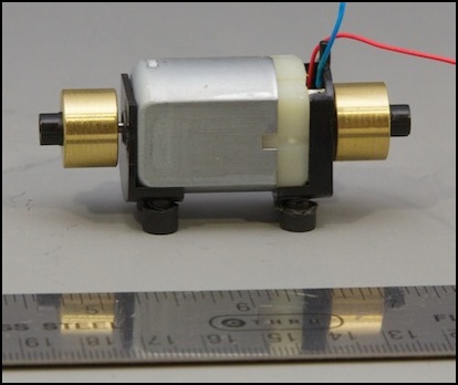
This is a bit of history. The DC-71 is probably the motor that can claim the longest production period of any model train motor, and perhaps of any model train component. The DC-71 was originally introduced by Pittman in mid-1946, at a price of US$7.00 and was popular both for repowering and as original equipment in many steam locomotive models. It went through a number of revisions over the years, keeping the same basic design but improving with the times. Sometime around 1980 Pittman sold their open-frame motor line to Bowser, although they still make can motors, and Bowser kept on producing the DC-71, among other models. In 2001 Bowser introduced an updated version of the DC-71, now sporting a skewed 5-pole armature. This apparently produces slightly less power than the original, which isn’t very surprising as that’s to be expected from a skewed winding, which trades power for less cogging (smoother low-speed operation). This copy was bought new in early 2014, for US$30, so the model has been in production for 68 years, if you count the design variations as one model of motor.

In this motor, the magnet is the large silver block on the right, and the top and bottom black metal parts are steel, to conduct the magnetic field around to the top and bottom of the rotor. The separate front part, although also black, is likely made of brass to avoid conducting the field.
The motor had a stall current of 1.0 - 1.1 Amps at 6 volts, which implies a stall current of 2.2 Amps at 12 volts and 3.3 Amps at 18 volts, so you’d need a really hefty DCC decoder for one of these. R = 6 Ohms, and L = 1.5 mH. This equates to a minimum DCC frequency of 4.0 kHz.
