


Benchwork
I have a fairly good idea of what my benchwork will look like. I covered some of this in past Musings, and my thoughts haven’t much changed (see here and here). But plans do change and evolve, and I don’t generally go back and edit musings, so going forward this page will track the current plans for my benchwork.
Note: numbers here are still not final, and subject to change before construction begins.
Wall-Hung Benchwork
So the first thing is how the benchwork against the wall will be built. I’ve made this a bit more complicated since that original post, partly due to a better understanding of how L-Girder construction is supposed to work. Now I’m planning a set of joists above the girders, and a set of supports below them. What this means is that the fascia will be taller. That’s actually a plus, as I’m now planning some fascia-mounted controls, and I want a shelf, so having some space between the shelf and where windows to the subway layer will go is beneficial. Not all sections will have subways, so “ground” level may be lower where that can be eliminated.
The subroadbed and related structure is discussed more on the Trackwork page, but will be 3/4” (19mm) plywood, which I may also use for the supports and brackets to limit warping. The actual plywood may be marine-grade or birch (I’ve seen both recommended, and need to do more research there).
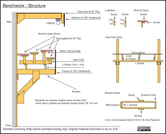
Let’s look at this in a bit more detail:
Several requirements affect this structure, all of which are related to visibility and use, not just for myself but for others who might visit or operate the layout when it’s built. One goal here is to make the layout “wheelchair accessible”, both for visitors and in case I’m mobility-impaired in my later years. Actual work on the layout (including cleaning track) would require standing. I can’t see any way to avoid that without making compromises on the flexibility of the table structure (e.g., the subway space) or limiting under-table clearance (which makes working on the underside problematic).
Here are the general requirements I am trying to satisfy:
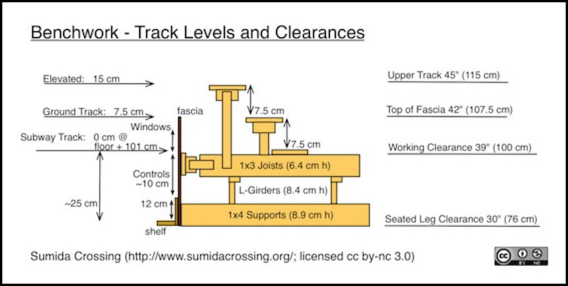
- The Supports need to be high enough to allow clearance for a seated person in a wheelchair (to allow turning in narrow aisles). Per AADA this is 27” (69 cm).
- Track and scenery will sit on risers connected to the Joists, and need to not exceed a reasonable “eye height” for a child or seated adult (see below).
- Track levels need sufficient spacing for subroadbed, roadbed, track and raised pantographs. With 19mm subroadbed this is about 7.5 cm (see my Straight Track Standards page), although I may increase this slightly.
- I need to be able to work under the layout comfortably for long periods.
- L-girders running parallel to the wall need to fit between the Supports and Joists.
- The Fascia must be tall enough (most places) to allow one layer of “underground” tracks (for subway or other use).
- There should be room on the Fascia below the windows for the subway to allow for control panels and/or video-camera displays for hidden tracks. I’m estimating 4” (10 cm) for this, but that is approximate and I could use more in places where there is no subway near the fascia (i.e., where a camera display is most likely to be needed).
- The shelf should be at a level for casual “put something down” use, and is intended to keep tools and coffee cups off the layout, rather than being used as a writing desk for train orders.
The puts the highest trains at about 115 cm (45”) above floor level, which is close to the level used for the original Sumida Crossing, and I’ve been fairly happy with that (that layout wasn’t planned for a specific height, it was just built “to feel right”).
In designing for eye-height, I took the average height for an 8-year old (50”, 127 cm) and assumed that made “eye level” around 46” (117 cm). This would allow older kids to see the layout without needing to stand on step-stools as long as “ground level” was slightly below that. Younger or shorter kids would still need step-stools or adult help, so it’s not a complete solution but it’s the best compromise I can see with other goals. This is also a reasonable, although not ideal, height for an adult in a wheelchair (AADA eye level 43” - 51”, 109cm - 130cm). I could try to lower the scenery level some, but I think it would become problematic for standing adults and I run into clearance problems. I’m not done thinking about this, and may change my numbers again before construction begins.
For underside clearance, one large goal is that I want to be able to sit up underneath the layout when working, because the electronics will be mounted to the back wall and I don’t want to be hunched over when working on them. That means I need about 39” (100 cm) of clearance to the lowest solid layout structure. I can work around the brackets that stick out from the wall. Assuming I can also work around the L-Girders, then the joists and the subroadbed immediately above them will be the limiting factor. I could actually lower this several inches since the first lengthwise structure will be the subroadbed of the subway, which generally won’t be near the back of the layout.
I have three levels of track planned, although each “scene” will have specific needs. In general I want an underground “subway” level, ground-level tracks and one “elevated” level. Although not show a Shinkansen viaduct level might be above the elevated level, although perhaps not crossing it and thus not a full 7.5cm higher. Ground level also won’t have tracks in many places (or will have trams, with different clearance needs) so the elevated tracks could be lower in some places.
If I place the bottom of the Fascia at the top of the Support (behind the shelf backsplash) then the fascia winds up being somewhat just under a foot tall, which will avoid wasted material when cut from 4x8 sheets. It also means plenty of open space behind the fascia, where I can put wiring for fascia-mounted controls without getting tangled up with DCC wiring or wires for building lighting. And the space above the joists can be used for subway stations visible through fascia cutaways.
The shelf along the base of the fascia is fairly low, but not unreasonable for a standing adult as a place to set down a drink or tool. Part of its purpose is to provide a support for the fascia, to keep thinner material rigid between the joists (I may glue a strip of plywood to the back of the fascia as well, for that purpose). It’s also there to protect the fascia from impacts (i.e., people bumping into it) that might damage it. The shelf is too low for writing, but in general I’m not planning any form of operation that would require written forms. Those don’t seem appropriate to what I’m modeling.
I’m also planning to have at least one work-desk built into the structure, and these numbers work fairly well for that (the below image presently has some slightly older info, but it’s mostly correct).
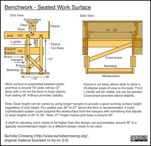
The dimensions for the desk need a bit of rework. I’ve lowered joist height slightly, so I need to raise the bottom a bit to get it to clear 27” above the floor.
