


Microcontrollers and LEDs
An LED is a Light-Emitting Diode, which I’ve covered separately on my LEDs for Modelers page. But using LEDs with a microcontroller such as an Arduino adds come complexity.
This page incorporates what used to be my “Arduinos and LEDs” page, but it’s been significantly updated (as of 2016) to generalize it for use with other microcontrollers and new forms of LEDs.
Basics
First a bit on LEDs themselves (repeating some material from my more general LEDs for Modelers page) and how those are used with microcontrollers.
Voltage and Resistance
The original Arduino came in versions with two different base voltages: 3.3V and 5.0V (I’ll ignore the LillyPad models, which operate over a range of voltages, since they’re mostly for clothing). Most operate on 5V power, but the Pro and Pro Mini are also available in 3.3V versions. The later M0-based Arduino models (the Zero, and Adafruit’s Feather M0 line) operate on 3.3V, as do other microcontrollers, such as the Raspberry Pi. You should understand the native voltage of the specific model you are working with.
Note: “native voltage” does not mean what comes out of the external power supply, it means what the chip uses. The power supply typically puts out several more volts, to allow for loss in the regulator. A 5V Arduino may use a 9V, 12V or even 15V supply, and similarly most 3.3V microcontrollers use 5V (or 5.2V) power supplies.
Pin Limitations
LEDs are driven directly off a “pin” output from the microcontroller, at least in their simplest form. While it is possible to have external LED-driver circuitry, that’s an add-on that isn’t needed for most applications. However, pins have limits, and building a circuit that tries to pull too much current through a pin will have fatal results for that pin, burning out the internal components that drive it.
Arduino’s are relatively robust. A pin can provide up to 40 mA (milliamps, or thousandths of an ampere), which is more than enough for most colored LEDs. However white LEDs and high-intensity LEDS can draw more, and some later Arduino’s and other microcontrollers have more stringent limitations. Know the limits of your pins, and the needs of your LEDs, if you want to avoid damaging the microcontroller.
The Arduino Zero, while otherwise a great microcontroller, is not really intended for directly driving external devices like LEDs. It has a pin limit of just 7 mA (you may be able to draw twice that without damage, but I wouldn’t count on that). A very small (surface mount) LED may draw that little, but some high-output SMDs are designed to draw 20 mA or even 30 mA.
The Raspberry Pi is more a general-purpose computer than a microcontroller, and similarly is intended to use its pins to communicate with other devices, not drive power-using circuits like LEDs. It’s per-pin limit is 16 mA, but the sum of all pins should not exceed 50 mA.
And once you talk about more than one pin in use at a time, the actual limits are much more stringent. Even with each output pin limited to 40 mA, you can’t turn them all on simultaneously. The total power consumption of the Arduino Uno is limited to 200 mA, and some of that is used to run the processor itself (not much, typical maximum CPU current is 9 mA). Finally, pins on an Arduino are related to groups of I/O ports on the chip, and these groups are typically limited to 100 mA per group (see the electrical characteristics section of the appropriate data sheet for specific details, and the schematic for the association of pin to I/O port; both are usually linked from the Arduino product page for the specific model of Arduino), in general this limits groups of pins to under 15 mA each if all are in use. Other microcontrollers have similar structure: pins are in banks with per-bank limits (often poorly documented) and the power supply (regulator on the board) will imply a global limit.
Trying to directly drive more than a couple of small indicator LEDs with more limited microcontrollers is not a good idea, and even on the Uno it’s constrained. For larger projects, you may need to use external driver circuitry (e.g., transistors or driver chips) so that a tiny current from the microcontroller can control a larger current for the LED. But that doesn’t mean that it can’t be done. See below for more information about this.
There are ways to drive a LED some of the time, using pulsed power, to get around total power limits, while still making it seem like it is lit continuously. And there are ways to arrange LEDs that allows a smaller number of pins to control a larger number of LEDs, one of the most-used methods is called charlieplexing. With pulsed power and sequential lighting of LEDs, you can probably light around 40 LEDs on a standard Arduino without getting in trouble (and more if you’re really careful or use low-current LEDs). But here, software errors could be more serious: leave a LED on when you thought it was off, and you could overdraw and damage the pin(s) involved.
LEDs and Resistors
Because LEDs typically have an operating voltage (formally, the “forward voltage” or Vf) between 1.6 and 3 volts, a resistor in series with the LED is required to discard the excess voltage from a higher-power supply. The minimum size of this resistor depends on the supply voltage and the LEDs forward voltage and current ratings. Fortunately, things like signals that come with pre-installed resistors are sized for much higher voltages, so in general we can uses those as-is, with only a small reduction in intensity, and no risk to the signal LED or microcontroller.
But if you want to replace them, or make your own LED-using circuits, you need to understand what that resistor is doing, and how large it needs to be for safe operation. Get it wrong and either the LED, or part of the microcontroller circuitry, or both, will be permanently destroyed.
Assuming a 12 volt supply and a typical LED of 20-30 mA, to be safe a 680 Ohm, 1/4 Watt resistor should be used. That includes some safety margin for low-tolerance parts are variation in LED requirements. It also assumes a single LED is used in series (we’ll get to more complex arrangements later). If you reduce the voltage to 9V, you could reduce the resistor to 470 Ohms, and at 5.2V (a common voltage used with microcontrollers), a 220 Ohm resistor would be sufficient. And on 3.3V, all you need is 220 Ohms also (because there’s no handy lesser value, although 180 Ohms would work with 5% or better tolerance resistors). Once voltage is 5.2V or less, you can also use a 1/8 Watt resistor instead of 1/4 Watt.
In most cases, you’ll be working with the native voltage of the microcontroller, 5V (or 5.2V) or 3.3V, so the resistor for a single LED should be 220 Ohms minimum (it can be larger, as we’ll get to). However, if you use the microcontroller to switch external voltage supplies (e.g., using a transistor) then you need to use the voltage that is applied to the LED, not the native voltage.
This is all calculated using Ohms Law (V = I x R and its variations), and power is simply W = V x I. So, for example, the 12V number above was derived as follows. Assume a worst-cast 1.6V forward voltage (worst case is lowest here, so this is safe for 3V forward voltage LEDs also) and 20 mA (again, lower is worse here because we drop less voltage at low currents). R = V / I = (12 - 1.6) / 0.02 gives us 520 Ohms as a minimum resistance. Assuming 10% error, we round up to 572 Ohms. The next standard size above this is 620 Ohms, but 680 Ohms is more common, so I’ve listed that as the minimum. In truth, with 2% resistors and assuming you know 1.6V is the real target, all you really need is 531 Ohms of resistance.
Oversizing resistors will make LEDs draw a little less current, and be a little less bright. But this doesn’t happen in a linear manner. Doubling the resistor is probably going to make a barely noticeable change in intensity. So rounding up by 31% as we’ve done here isn’t going to have a perceptible impact in any model railroading application. In model railroading systems, designers of LED-based devices, like signals often assume a worst-case voltage or 18V or more will be used, so you will see resistors of 1 kOhm or more, but even if you leave those in place, the result when driven from a microcontroller is likely to be only a small reduction in brightness. In a very bright room (e.g., at a modular railroad show) it might matter, but under normal layout-viewing conditions, it’s probably not worth the effort to replace existing resistors.
Power (in Watts) is simply volts times amps (P = V x I), where volts is the amount discarded by the resistor. So P = (12 - 1.6) x 0.02 = 0.208 Watts, or 208 mW. That’s below 1/4W (250 mW) and above 1/8W (125 mW), so we need to use a 1/4 W resistor to avoid damaging it.
The last thing to consider is that some LEDs use less current, and those need larger resistors. What the resistor is doing is discarding voltage, and how much it discards depends on the current (that’s really all that Ohm’s law says). So, if you needed 180 Ohms on 5.2V at 20 mA, you’d need 360 Ohms for a LED that draws 10 mA, and 720 Ohms for one that draws 5 mA. And some surface-mount (SMD) LEDs really do use as little as 5 mA.
SMD LEDs haven’t been common in the past, but they’re increasingly finding applications in model railroading. The ones I’ve seen to date have mostly been higher-current models (although the ones used in car-lighting circuits often draw only 5 - 7 mA). This is another reason why 1 kOhm resistors can be a good idea; they may be needed if you aren’t sure of the LEDs characteristics, but you think it might be a low-current model.
Chaining LEDs
This doesn’t usually apply when controlling LEDs, but if you have two LEDs in series (i.e, one after the other) on a pin, you can light both with one pin. This only works if the pin voltage is larger than the sum of the LED voltages (so it works on 5V models of microcontroller, but usually isn’t possible on 3.3V models, because 2 x 1.6V is close enough to 3.3V that it’s probably not going to work reliably given the usual kinds of rounding errors that go on with electronic components).
If you do have enough voltage, then the resistor needs to discard only what’s left after subtracting that (e.g., for two 1.6V LEDs on a 5.2V supply, that’s 2V, or a 120 Ohm resistor at 20 mA (rounding up from 100 Ohms).
Using LEDs
There are a number of ways LEDs can be used with a microcontroller. The simplest is as an indicator light: turn it on to report one condition (like a switch thrown to the diverging route) and off for another. For those, we wire the LED and resistor in series, between the microcontroller pin and ground. One pin, one resistor, one LED. Very simple.
It’s also terribly inefficient. There are a limited number of pins, and you may want to use many of them for other things, so you’ll run out quickly doing this. And while a typical Arduino can provide the 20 to 40 mA needed to drive a LED, many other microcontrollers can not do so (even some newer Arduino’s, like the M0 models, are limited here).
One LED, More Power
The simple solution if you just just need to drive one LED with more power than the microcontroller can provide is to use a transistor as a switch. The diagram below shows the basic configuration:
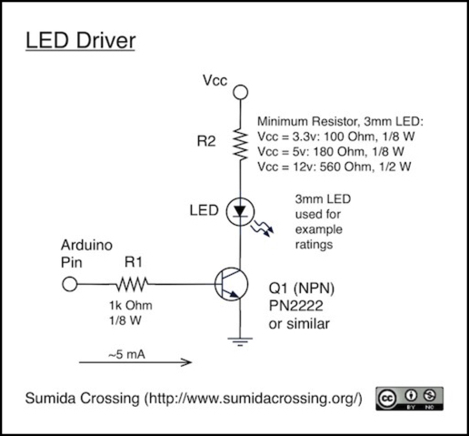
The LED plus R2 portion of the circuit is the standard LED circuit, with R2 sized based on the supply voltage and desired maximum current through the LED. The only difference is that some voltage will be lost in the transistor (Q1). However, this is small (and variable), so we’ll just ignore that, and calculate the LED current normally. Let’s take a typical small (3 mm) LED. This will have a Vf of 1.5 to 2.8 volts, and a current of around 20 to 30 mA. A 5 mm LED would have similar voltages, and a normal worst case current of 40 mA.
So, Ohms Law tells us that the required resistor for a 5V supply is (5 - 1.5) / 0.020 = 175 Ohms, or rounding up to the next size, 180 Ohms. Power lost in the resistor is given by P=VI, so the worst case here is 2.8 x 0.030 = 0.084W (84 mW), and a 1/8W resistor is sufficient. Even a 5mm LED wouldn’t need more. The numbers on the diagram were calculated using this approach, and represent the smallest values safe to use, larger will always be safe, and but won’t produce significantly less light unless you go over 1 kilo-ohm. Even at 12V, you might get away with a 1/4 Watt resistor, depending on the LED current.
Some LEDs, in particular white LEDs, have different characteristics, and might need different values and ratings for R2.
R1 acts to limit current from the output pin. A typical transistor will lose roughly 0.6 volts across the base-emitter junction, so a 5V Arduino will have a voltage across the resistor of about 4.4 volts, while a 3.3V Arduino will have a voltage around 2.6 volts. For example purposes I’ll use the 2N2222 NPN-type transistor (also sold as the PN2222), but there are many others suitable. When choosing a transistor, Ic, the “Collector Current” (i.e., the current through the LED in this case) is usually the most limiting factor, but since LED currents are so low, nearly anything will work. If you were controlling something like a motor, you’d need a more robust transistor.
The typical NPN transistor needs only a few milliamps to turn on, with 5 mA a safe number for a full-size LED. A low-current surface-mount LED could be controlled with a lower pin current, but won’t be bothered if we use a higher one. This depends on the gain of the transistor and the current through the LED (if the pin current times the gain is less than the LED current, we’d be limiting it, which we don’t want to do). However, we do want to keep the pin current down to stay within the safe range (some transistors could be damaged by more than 10 mA, although many are more robust) and to limit power use on the Arduino. We’ll take 5mA as the target current from the Arduino pin.
Ohm’s Law (V=IR) tells us that R=V/I, so for a 5V (4.4V effective) Arduino, we want a resistor of size 4.4 / 0.005 = 880 Ohms, rounding up to the next standard size gets us 1 kOhm. For 3.3V the result is 660 Ohms, rounding to 680 Ohms, but even there 1 kOhm will probably work just fine.
Often, however, you don’t want to control just one LED per pin, and that takes us to more complex methods.
More LEDs - Multiplexing
The basic solution to doing more with less on the Arduino (or other microcontrollers) is “multiplexing”. LEDs are no exception. This can get rather complicated through, and there are a number of issues to deal with to make this work.
If you want to control something really large, like a dot-matrix display, you may be better off using some external circuitry. Arduino has an example page describing use of a LED Driver chip if you want to go this route.
Many people use, and like, this approach. One thing I don’t like about this is that it takes time to signal the chip, and you have to use delays to ensure precise timing of that signal, so you lose something more than 560 microseconds each time you want to change which LEDs are lit. That may not seem like much, and in many cases it won’t be, but if you need to change them a lot or you’re doing other things that need time, it adds up. This solution I’ll describe below uses 12 microseconds of processing time once every 1,000 microseconds to drive twenty LEDs. My method could still use more time overall since you’re unlikely to change the state of the LEDs too often, but it’s time that’s evenly distributed, and that’s an important characteristic when you want the program to be off doing other things most of the time.
Persistence of Vision, or Not
Things like movies and television work by exploiting the fact that the brain remembers what it’s recently seen if there’s a short gap. This is called persistence of vision or “flicker fusion”. And if you look around the web, you’ll find references that say that as long as the gap between events is less than about 11 milliseconds, you can’t perceive it. In fact, it’s a rare person who can notice gaps even that long under intense scrutiny. As you’ll see in a bit, it’s not quite that simple, but the principle is correct. Film projectors use this to display a frame for a short period before blocking the light to advance the film; the brain fills in the gaps when the screen is dark, as long as there’s a new frame at least 16 times a second (i.e., every 62.5 milliseconds). At that rate, some flicker is noticeable (think about old silent movies and how they appear). Modern film uses 24 frames per second (41.7 milliseconds), video is 30 fps (33.3 ms) and computer games are often designed to run at 60 fps (16.7 ms).
But a LED isn’t quite the same as a motion picture screen. For one thing, a movie has lots of dots on the screen, and they’re constantly changing color and intensity. A LED is a single dot of one brightness. It only makes sense that it would be easier to notice changes, and it is. You can trick the eye into seeing continuous light instead of flickering, but the numbers are different.
I modified the standard Arduino example program Blink to turn an external 1.5mm red LED on for a specific number of milliseconds (or microseconds) then off for a different number of milliseconds each time around the loop. I discovered several interesting things from this. First, the LED doesn’t need to be on for long. It gets dimmer at shorter durations, but even if it was lit for just 5 microseconds (not milliseconds) out of every 20 milliseconds I saw it as continuously lit. That’s just one part in 4,000 (I suspect it was lit longer, as the transistor probably can’t switch that fast and the diode probably glows for a short time after power is removed, but still it didn’t take much to appear lit).
The second thing is that it’s easier to see short gaps than short pulses of light. If I lit the LED for 100 milliseconds, and turned it off for just 4 milliseconds (not microseconds), I could see it flicker.
So what this means is that when structuring a program to deal with multiple LEDs, I need to make sure they’re on for much shorter times than they’re off, so that the viewer sees a continuous but dim light, rather than a bright but flickering one.
Cycle Speed
The other part of this is that if the delay between lit phases was much longer than 20 milliseconds, I could see flicker anyway (25 milliseconds was somewhat visible, 30 milliseconds was obvious). That agrees with some of what I read, which is that rates above about 50 - 60 Hz (17 msec to 20 msec maximum between pulses) were needed. That is not the whole story, however.
So what I need to do is ensure that roughly every 20 milliseconds each LED that’s lit is lit for as long as possible (to get maximum brightness), but that “as long as possible” can be quite short if I was willing to accept a relatively dim light. In theory I could light 4,000 LEDs this way, and use the power needed to drive just one. In truth it’s not that simple, as power is lost turning them on and off (switching power in the transistors). But still, this means that it is possible to drive lots of LEDs with the limited power available from an Arduino and structure things in such a way that different ones are on at different times (i.e., with multiplexing).
One way to drive LEDs like this, incidentally, would be to use PWM. But typically only 6 of the 14 digital pins on an Arduino are capable of PWM, and they’re tied to a small number of unique timers, one of which has to run at a specific standard rate in order for millis(), micros(), delay() and delayMicroseconds() to work properly. So instead I’ll use the time functions to do it myself, which gives me more pins and more flexibility. While the newer M0-based Arduinos have more pins with PWM capability, they also have less power total, making it harder to use this approach with them.
Video
But is ~20 milliseconds really the right interval to use? This should work fine for the human eye, but what if you’re filming your layout in operation?
A typical film camera operates at 24 frames per second (which for arcane technical reasons is actually 23.976 frames per second). This works out to 41.7 milliseconds. So each frame of video is taken ~42 milliseconds apart. But it doesn’t stay open the whole time. And if the LED doesn’t light up while its open, then it will be dark. Worse, because the LEDs and shutter cycles at different rates, over the long term (large fractions of a second) different ones will be caught by the shutter, causing the LEDs to look like they’re flickering, or even turning on and off slowly over time.
So clearly, the cycle time needs to fit within the speed of a typical camera shutter if you want the LEDs to look stable on video. But what is that? Well, for technical reasons this has historically been twice the speed of the frame rate. So for film, this works out to 20.8 milliseconds, and we would have just over 20 milliseconds to cycle through all of the LEDs. But video is more typically shot at 30 fps, and has frames lasting just 33 msec. And a lot of modern cameras will work at 60 fps, which is often rounded to a 1/125-second shutter. So to really be safe, I need to keep my cycle time under 8 milliseconds (for more on this, see my Musing on video and LEDs. That’s tighter than I thought it was going to be.
Even faster shutter speeds may be desirable to deal with motion blur. Someone really serious about video, using a high-end camcorder or DSLR that can shoot video with adjustable shutter speeds, might want to have LEDs cycling even more quickly so they could shoot video at a higher shutter speed (my new DSLR will do this). There’s a practical limit to this, as there’s only so much light available and faster shutters mean less light on the sensor. Still, a shutter speed of 1/250-second would leave just four milliseconds to cycle through the LEDs, and such a shutter speed would easily be possible. I don’t think I can allow for that; there’s just not enough time to get through “loop()” quickly enough. So I’ll aim for a hair under 8 msec, but I may revisit that decision if I can make things run quickly enough. And if I were designing an Arduino program to perform more specialized control (e.g., a simple signal driver), where I had less work to do overall, then I’d probably try to cycle the LEDs at a higher rate.
Note: one reason fast shutter speeds aren’t normally used with video, aside from exposure, is that show shutter speeds take a series of blurry pictures when something is moving or the camera is panning. It turns out that this looks “more natural” to the human eye than a series of sharp-but-changing pictures. That’s not to say that someone couldn’t used fast exposures, but for the average person, we’re probably safe at 8 millisecond cycles.
In summary: if you want to be sure your LEDs will look good on video, get through them in under 8 milliseconds. Depending on your video camera, 16 milliseconds may produce acceptable results, but don’t take longer than that. The eye won’t see a problem at 20 milliseconds, but a video camera will.
Multiplexing and Charlieplexing
Multiplexing in its simplest form arranges things in rows and columns, such that each object (LED) is active when both its row and column are selected, and not otherwise. This allows, for example, 8 control lines arranged as a 4x4 grid to control 16 LEDs, a two-fold multiplier. But there’s another technique, named Charlieplexing (after its inventor, Charlie Allen) that’s more complex, and allows N control lines to drive N collections of N-1 LEDs. With this, 8 lines could drive 56 LEDs (assuming sufficient power was available to light them all, which becomes an issue).
Charlieplexing depends on the fact that microcontroller output pins don’t have just two states, high and low, but actually three: output high, output low, and input, which in effect is neither on nor off. And it’s easily structured around clusters of LEDs that have a common anode or cathode wiring arrangement. This turns out to be quite handy for model railroad signals, as these are usually wired with all lights in a signal having a common wire on one side (typically anode for LEDs, although it could vary).
Also, while a signal might have two LEDs sharing an anode (for example), that doesn’t mean you’re limited to clusters of that size. Two signals could be wired together into one cluster of four LEDs. The limiting factor is going to be power: how many of those LEDs need to be lit, how many milliamps are they using, and what are the limits of the power supply (per pin or total). There are some issues to be aware of with this technique. They’re summarized quite well on this page, so I won’t bother to restate them here. But the circuit design given below, and the program to use with it, take these into account.
Charlieplexing LEDs with Arduino
First, I’m going to use two different colors of LED in this example, since I’m planning to use the circuit for controlling a set of red/green signals. Second, I need to be able to have more than one LED lit at a time, which the circuit can’t do, so I’ll use persistence of vision and blink the LEDs so that more than one appears on even though current is only flowing through a single LED at any given moment. Here’s my circuit plan for controlling twenty LEDs (five sets of four) with five Arduino pins. Using two-color signals, this is going to prove for up to ten signals (e.g., the LEDs associated with Rc11 and Rc12 in the diagram are one signal mast with a two-light head). This can easily be generalized to three-light signals, or more sets, or both, using more pins. The next step up would need seven pins to drive three two-color signals or two three-color signals per set, and seven sets (for 21 two-color signals or 14 three-color signal masts).
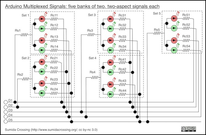
Notice that there are resistors on both sides of the LEDs. The RsN resistors are on the anode (positive) side, and serve to block current from the cathode (negative side) of one LED from recirculating into the anode of another set. This is necessary because an Arduino pin in LOW state isn’t quite at ground due to internal resistance, keeping the LED cathodes above ground. Without these, I had unintended LEDs that lit faintly (or sometimes not so faintly). I found 100 Ohms to be a good size for these, although this was probably underdriving the LEDs (with two LEDs lit, I could have had 40 mA flowing, which means I’d be dropping 4 V of the 5 V present; realistically much less current would flow and thus the effect would be less). I need to experiment with other size resistors and see if I can reduce these to 50 Ohms or less (while possibly increasing the ones on the cathode side).
Note: one significant difference in this diagram from normal charlieplexing diagrams is that it uses separate resistors on the high and low sides of the LEDs, rather than putting one resistor on each pin and sharing them. There is a reason for this. It has to do with variations in how many LEDs in a bank are lit, which we’ll cover further down the page. But for now, just take it as being worth the few extra cents that a few more resistors cost.
The resistors on the cathode side are there to provide each LED with its own resistance, as two dissimilar LEDs sharing an anode resistor that are both lit may light at different intensities if there’s nothing to prevent all or most of the current from using one of them. For my experiments, which were carried out with red and green LEDs with Vf of 3V and currents of 15 and 20 mA respectively, I found 68 Ohms to be a good size for these (but see the comments below). When I used the same circuit with a NJI International signal with SMD LEDs, it worked but was fairly dim, so I’ll need to experiment more to find good values for typical signals.
Note: I used Radio Shack 276-0026 (3mm low-intensity RED, 3 V, 15 mA) and 276-0022 (5mm green, 3V, 20 mA LEDs) for my testing if you want to exactly replicate the circuit. All resistors were 1/8 Watt (well, some were 1/4 W because I couldn’t find enough 1/8 W ones, but they only needed to be 1/8 W).
Still, it works. The software to drive them is a bit complex although conceptually quite simple, and in any case it meets my goal of running a large number of LEDs from a small number of pins without spending a long time communicating with an outboard controller. As noted above, my code used just 12 microseconds every 1,000 microseconds, so I can add it to other programs without having to be concerned with adding unexpected delays in time-sensitive processing. That’s important for the kinds of programs I’m likely to use this in.
It’s easier to show how this works than to explain the program, so I’ve constructed a sample sketch to drive the LEDs in the diagram above, which I used to test the behavior of the charlieplexed LEDs and my planned use of them, and that’s available (download it here) if you want to see it (as with all of my code, it’s public domain so you can use it to make your own programs).
N-Scale Signals
My initial purpose in doing this is to drive signals, so let’s take a look and what that means for the circuit.
First, with the signals I’m using, I can safely assume that either red or green will be lit, but not both. That’s handy, as I can tighten up my loop to drive one signal per cycle instead of one LED per cycle, making my cycles twice as fast with still limiting current to that of one LED. There are some signals that light two or more LEDs on a signal head (Japanese signals) or even three (position signals, used in both Japan and the U.S.), so as a general solution that won’t always be possible. In those cases, you may need to settle for driving multiple LEDs simultaneously, which will work as long as you keep the total current under the 40 mA limit of an Arduino pin.
Second, I’m going to be using some specific signals, either New Jersey International #2002 or #2004, or Tomar N-857. The NJI signals are marginally less expensive, so let’s use these for this example. Because the signals aren’t documented as to the LEDs forward voltage or maximum current, we first need to determine that. I can estimate that these are likely around 10 mA because they’re SMD LEDs (there are high-current SMD LEDs that draw up to 30 mA though) and because they’re supplied with a 1,000 Ohm resistor for 12V use (which implies a LED with 10 mA current and Vf of 2 volts).
If we assume the LED will have Vf=1.6 volts, and a current of 10 mA, then to run it safely on 5V I need to use a (5 - 1.6) / 0.01 = 340 Ohm resistor or larger. So the first thing I do is stick a signal on a breadboard with a 390 Ohm resistor (what I had handy) and connect one of its LEDs to the +5 and ground pins on my Arduino with that resistor in line. The LED lights (good sign), and I connect my multimeter across the two legs of the LED I’ve wired up, measuring the DC voltage across it as 2.00 Volts. Now Vf will vary slightly with current, but it generally stays close to one voltage, so I can estimate my LEDs at Vf=2.0 V. Next I modify the circuit slightly to measure current through the LED with my meter (keeping the same resistor), and see a current of 7.4 mA. This is a good first approximation, but let’s firm it up a bit.
Recalculating (still assuming 10 mA, my required resistance is probably (5 - 2) / 0.01 = 300 Ohms. I wire up a pair of 150 Ohm resistors in series and check again, the reading now is 9.6 mA. That pretty much confirms that I guessed correctly. Why isn’t it 10 mA? Well, first the Arduino doesn’t put out 5.0 volts. According to my meter, it’s 4.92 today (it can vary slightly with the supply voltage, which can vary with the line voltage). Second, my resistors aren’t exact (although they are 5% ones), and actually total 296.5 volts, and (4.92 - 2.0) / 296.5 = 9.85 mA.
But since we don’t need to be exact, this says the my signal LEDs (I tested both red and green and they were identical) have Vf=2.0 V and I=0.01 A. And that means that on a nominally 5 Volt Arduino output, I need about (5 - 2.0) / 0.01 = 300 Ohms as previously calculated.
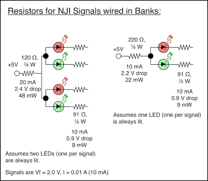
Now going back to my driver circuit, how do I divide that between the RsN and RcNN resistors? It’s not as simple as half each, because while the current through RcNN is 10 mA, the current through RsN depends on how many LEDs in the bank are simultaneously lit. If on one was, both would have 10 mA. But if, as planned, I light one LED per signal, that means my bank of two signals will have two LEDs lit, and current through RsN will be 20 mA.
I saw in my earlier experiments that 100 Ohms was a good size for RsN. I haven’t actually tried smaller ones, but what happens if I use that size with a current of 20 mA? It drops 100 x 0.02 = 2 Volts, dispersing 2 x 0.02 = 40 mW, so I can safely use a 1/8 W (125 mW) resistor if I want. That still leaves me with 1.0 volt to drop to take 5V down to 2.0 V. With a current of 10 mA through RcNN that means I need 1.0 / 0.01 = 100 ohms on the output side as well (also a 1/8 W resistor). That’s nicely symmetric.
But is symmetric good? Perhaps I’d be better off making the one between the high pin and the LED larger, just to make the path to ground even more preferable (in truth, it shouldn’t matter, and symmetric ought to work too). A bit of calculation shows that 120 ohms will work on the high side, with 91 on the low side. Total voltage drop is 3.31 volts, slightly more than the 3 I want to drop, but that’s good, as it provides a safety margin for variation in the actual resistance and most of the time it makes the current through the LED lower than maximum, which is good for the lifespan of the LED. It also would protect them if for some reason the Arduino decides to put out 5.1 instead of 4.9 volts.
Note: 91 ohms is a 5% size, and might be harder to find than 100, so 100 + 100 will work if you can’t do 120 + 91.
But wait, what happens if I’m using an odd number of signals (I’m not for my Tram project, but what if I was)? That means that one bank will have one signal in it, rather than two. And for that bank, two 100 Ohm resistors aren’t enough. One of them (either) needs to be raised to at least 200 Ohms (or 220 Ohms, which is the more easily-found size, and I think a better choice). That would also be what I’d need to use if I didn’t make the code take advantage of the wiring; if I only light one LED in a set at any given instant, I need the larger resistors (220 Ohms), but if two are simultaneously lit, then I can use the smaller ones (120 Ohms).
If I raise the high side resistor to 220 ohms and drop the low side to 91 ohms, I get a voltage drop with one LED of 3.1 volts. With two I’d appear to get a drop of 5.3 volts, which can’t happen with a 5-volt supply, so what really happens is that the current drops (perhaps enough that the LED won’t light, or perhaps just lighting it dimly).
So this is what I’d use with the NJ signals, which as noted draw 10 mA with a Vf of 2.0 volts, meaning that I have to lose 3V from the Arduino’s 5V supply in the resistors. If I used different LEDs (e.g., for HO I might have 20 mA non-SMD LEDs with Vf around 1.8 Volts, meaning I’d need to drop more volts, but would use smaller resistors due to the higher current). Or I might have the LEDs I found in my local Radio Shack, which have Vf of 3 volts and currents of 15 and 20 mA (which makes things a bit more complex; I used 100 ohms on the high side and 67 on the low side with those, but that was actually larger than it needed to be.
