


Construction
Test Track Construction I - Plan to Roadbed
After entirely too long dithering about, it’s time to actually lay some track. Or at least, begin the process.
As I mentioned in my earlier post on Planning a Test Track, this is going to replicate the crossovers west of Ochanomizu Station, which will allow me to test prototypical signaling, as well as operation of trans through some complex crossovers on my planned code 55 rail. If I’m going to have problems with that, this is where I want to discover it.
First, I made some basic tests, running cars by hand on Micro Engineering Code 55 flex track, both with wood and concrete ties. This was just to determine if typical wheels would have problems with the low profile (e.g., bumping into moulded-on spikes, etc). I tested with Kato, Tomix and Micro Ace models, both passenger and freight, and all worked flawlessly. These were all of relatively recent manufacture, but it suggests that I’ll be able to use code 55 rail without problems.
My fallback plan was to switch to code 70 track if this didn’t work, and that still might happen if problems turn up on the test track. But I’d really prefer to have the lower-profile rail if possible.
Designing the Track Plan
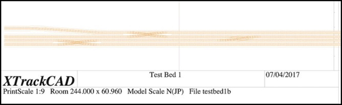
I laid out a track plan eight feet (244 cm) in length, to fit my pair of four-foot long boards. A print of this is shown at the top of the post. For this I just included two #8 double crossovers and a single crossover, the latter made from facing #8 switches. I also tried my hand at widening the inter-track spacing of one line, mostly to see how well i could do this in XTrackCAD (see my XTrackCAD page for details), but it would also provide a test of car behavior on an S-curve (I put a 20 cm straight section between the two curves).
This is slightly compressed from the prototype. The actual distance from the bridge at the end of Ochanomizu station where the half-crossover is located to the second double crossover is about 550 meters, or nearly long enough for three ten-car trains (each of which are about 200 m in length). The total distance on my test board is eight feet, which in 1:150 (Japanese N Scale) equates to about 366 scale meters, slightly shorter than two “200 m” model trains (which are about 4’ 5” each), and the crossings are even closer to each other.
One goal of my modeling is to make the space between stations large enough that a train seems to spend time traveling from one to another. On the original Sumida Crossing my two stations were about 2.5 m (7.5 feet) apart, but that was with a curve, which made the space look even longer. So another purpose of this track is to let me see how models will look on such a replica of prototype track if I do a “scene” of the interlocking between the two stations as a mostly-straight track.
I left a roughly 6” (150 mm) margin on the “front” of the board, and most of the back half is empty. This will provide mounting space for electronics and circuit prototyping boards (where I’ll put LEDs and resistors to fill in for signals). I was also careful not to place any of the switches near the edge of one of the physical boards, so that I could have removable track across the gap of sufficient length to adjust for any minor alignment problems.
Most of the track plan creation followed the same basic process I described in my Learning XTrackCAD post last year, but the S-curve was new. As described on my XTrackCAD page I created this using two eased curves over a total length of about 50 cm, creating a smoothly flowing widening of the inter-track spacing. This looks good, and the numbers seem to be right, but I’m going to have to build it and run some trains through it to be sure it works as well as I expect it to.
One potential construction problem I have is that the 28 mm center-to-center track spacing I’m using is less than the 31 mm width of the base of the Woodland Scenics foam roadbed I plan to use, which will mean I need to trim each piece when creating paired tracks, which will be most of my track. The result is likely to be less than perfect, but I should be able to hide that under ballast, and the outer edges can remain untrimmed.
As I’ve mentioned before, the 28 mm spacing is enforced by the double-crossover jig I’m using (hand-laid tracks, #8 double-crossover). This differs slightly from the 26 mm spacing I’d originally planned to use (NMRA standard straight-track spacing equates to 26.2 mm). For prototype Japanese commuter lines, the minimum legal spacing equates to just over 24 mm (see my Track Standards for Straight Track page for much more detail) and I found spacings much wider than 26 mm looked “unrealistic” to my eye. So 28 mm is not ideal, and I may use closer spacing on the final layout, away from crossovers, which aren’t all that common on most lines.
Transferring the Plan
Having drawn the plan, I then printed it out in 1:1 scale. Doing this was yet another learning experience (the online instructions skip over some of the important details). First, I used page setup in XTrackCAD to select landscape mode, since my layout was long and narrow. I also selected “any printer” and “US Letter” paper, since that’s what I’m using.
Then in the XTrackCAD print dialog, I selected a “Print Scale” of 1, meaning full-size, and set the width of the roadbed outline to 3.100 (it is in cm, as are nearly all metric measurements in XTC). In addition to checking “Print Roadbed” and leaving “Print Rulers” checked (it was on by default), I also checked “Ignore Page Margins”, “Print Registration Marks”, and unchecked “Engineering Data” (which meant I didn’t get page numbers, but I’m aligning these based on the rulers).
The registration marks are important, as you can measure spacing between them and check alignment over longer distances using a yardstick or long board, to make sure minor errors don’t slip in when you place the paper on the layout.
The thing it took me some time to figure out is that you have to “select” areas to be printed by clicking on the main XTrackCAD window after you have the print dialog open. This is useful since you don’t have to print everything, but it is very badly documented and without doing it the “Print” button is grayed out and won’t work.
I then clicked “Print”, which brought up a second window where I could select the printer. Here I selected “Print to File” and PDF format, and “all pages”, which gave me a PDF with all of the layout I’d selected.
Now at this point, things will vary by operating system. I’m on a Mac, so I used Preview to open the PDF and clicked Print, which gives me my Operating System’s print dialog. Here I changed from “Scale to Fit” (the default) to “Scale” and “100%” (the default for the printer I was using was 97%, which would have distorted the measurements). Here you can choose to print subsets of the pages, in case you have a problem and need to reprint one, or are only working on part of the construction at a time.
I did find that some of the track near the edge of the paper didn’t print in this mode. The benefit is that “Ignore Page Margins” means that you can line up the paper edge to edge and the registration marks will be the correct distance apart, which simplifies laying the paper out on the baseboard.
I then trimmed the printed paper so that only the track outline plus some extra bits for the registration marks every 10 cm remained. Holes were punched along the centerline, and then the paper was laid on the boards. Once I was sure it was all correct, a Sharpie was used to trace the edges of the roadbed and the track centers.
Next up: I need to start laying track.
Plywood and Sawdust
19 September 2013 23:34 Filed in: Construction
Building a new railroad starts with the planning, obviously, but it doesn’t really feel like it’s started until the sawdust starts to fly. Last week, after much re-thinking and dithering, I bought some plywood and let fly. Construction has officially begun on the One Point Five Meter Line (and I really need to think up a name for it). The concept has changed slightly since I first wrote about it a month ago. Then it was going to be three small sections (or maybe two) that connected together, and I was still thinking of a high-level platform line that would work for either light rail vehicles like my Setagaya trams, or single-car commuter trains.
The current concept, which could still be modified, uses low-level platforms and street track, and is more suited to light rail vehicles like the Portrams I covered last time. But what won’t change is the shape: that’s cut, glued and painted, as you can see above. It’s a single assembly, one foot (30 cm) wide and five feet (1.5m) long, standing six inches (15 cm) tall at the high end.
Read More...
More Hilltop Work
25 July 2013 23:44 Filed in: Construction,Scenery
Work has progressed. I finally finished getting the backdrop photo attached to the backdrop, and the latter attached to the layout table. This was not without a lot of awkward contortionism to get the darn thing bolted in place. Perhaps I would have been better off disconnecting the whole return loop end from the rest of the layout, so I could turn it and work somewhere other than in a two-inch slot up against a concrete wall. But while that’s possible by design, it’s REALLY hard in practice, and I decided I didn’t need to do it. And in the end I didn’t, although I’m not sure I actually saved any real time.
The backdrop looks pretty good, even in person. It has just the right level of detail, and the sizes are acceptable (perhaps a bit too large, but I don’t think they’ll be too obtrusive). The faded/hazy color and low-resolution of detail looks just right.
Read More...
The backdrop looks pretty good, even in person. It has just the right level of detail, and the sizes are acceptable (perhaps a bit too large, but I don’t think they’ll be too obtrusive). The faded/hazy color and low-resolution of detail looks just right.
Read More...
Mocking Up the Hilltop
It’s very pink, but with a bit of imagination you can see the forested hill rising behind the houses, which will have a small Shinto shrine tucked in amongst the trees, with a stairway down to street level, a very typically Japanese scene. This mock-up was part of my final refinement of the design for the Hilltop Scene. I’m not quite done, but I’m beginning to accept that I have a sound idea for what I want to do.
Read More...
Read More...
Hilltop Backdrop
11 June 2013 23:55 Filed in: Construction
It occurs to me that I haven’t said much about my plans for the hilltop scene. In fact the page I created to describe it is essentially blank. That’s mainly because I don’t have anything there yet to photograph, although I ought to add something showing the current appearance, if only as a “before” image. I do have a Construction page describing my plans and the current extent of work. he idea is that this is a removable “cap” that sits above the location of the future helix down to staging tracks.
Read More...
Read More...
Modeling Subways
I realized that my subway material was scattered over several pages, and I didn’t really have anything that tied them all together. Also, some of the pages were a bit out of date. The main page is the Subway Line page. I’ve updated the outdated material, and here’s a post to describe what I was trying to do, how I went about it, and what I’d do differently next time. I’ll link to other pages in the text below.
A subway isn’t something you find on a lot of model railroads, but then most model railroads are focused on freight operations. Even ordinary railroads back in the steam era had underground stations (New York’s Grand Central Terminal has 44 platforms, all underground). Property costs in modern cities make it even more likely for structures to be built above the tracks, partially or wholly covering the station. Boston’s Back Bay station used to be above ground, largely in a cutting, but today is mostly out of sight below ground except for the entrance building and ventilation stacks.
Despite the high property values in Tōkyō today, most of the stations are surprisingly at or above ground level. In part that’s because the rail lines’ growth came after dense urbanization, so elevated lines were a more practical solution for expanding them. The city does have subways, and most of them use the same gauge track and same voltage power supply as the above-ground commuter lines, so some of these subways provide access to the city center for suburban commuter trains. Several subway lines have underground stations below or near surface line stations, to allow transfers.
I’ve used that as an important aspect of my modeling to capture the “layered” feel of urban railroading. Cities rarely exist on a single level, even ignoring multi-story buildings. There are often below-ground open plazas and hidden shopping arcades, and highways and rail lines exist and cross on multiple levels. Cities aren’t flat, and models of cities shouldn’t be flat either.
Read More...
Getting Organized
23 September 2012 22:51 Filed in: Design,Construction
I’m not a very organized person. That may sound odd, given that this “blog” has a fairly extensive set of associated pages that are moderately well organized. But while I’m at least competent at organizing information, that skill doesn’t extend to the real world much at all.
When I started building the layout, I only had a few trains. Over the next two years I bought quite a few more, and partway through that the one shelf I had set aside for storing them became full and I expanded to half of a second. That filled, and there were no more available. Green Kato boxes began getting stacked in odd corners, on the layout itself, on the workbench, on shelves in the living room, and even in a small stack under the coffee table. For a while I managed to at least keep track of what I had and where it was, but late last year even that began to break down. As I mentioned last week, I somehow forgot to photograph one of my new trains (which was one of the few things I’d always done reliably, so I could keep track of them). And this summer it took me a week to find one of my older trains (the box was in a really odd place).
Read More...
Pylons
No, I’m not writing about the ones from the 70s TV series. These are the electrical kind, Kato kit 23-401, which is actually a Heljan-produced model, although apparently not one sold directly by that company. The kit contains material for three high-voltage electrical towers of a common design. In fact, they’re nearly identical to those in a photo of Shin-Yokohama described as owned by JR East (see my Electrical Reference Images page). List price from Kato USA is US$19, but I’ve seen them for less. Frankly, they’re overpriced for what you get. Read More...
More Wires
After saying I was going to finish up the DCC electronics several times, I’ve finally made a start. There are two parts to this. The first is finishing up the remaining DCC power protection and occupancy detector panels. I did the first three tables last year, starting around January. The third was the first I’d done as a removable panel, which I wired up back in November. At the same time I’d begun the work of setting up a third accessory power bus, adding a switch and meter to the main panel. However at that point I’d stalled, with my attention off the layout over the holidays, and when I returned it was to work on buildings.
Read More...
Read More...
Work Table and March 2012 Status
Work on the village buildings continues, although it’s been slow recently due to other demands on my time taking me away from layout work. This weekend, however, I found time to build a small work table. Read More...
Photographic Backdrops II and January 2012 Status
03 February 2012 23:32 Filed in: Construction,Monthly Status
I’d mentioned a few weeks ago the work I was planning to replace the old (and disintegrating) backdrop for the River Crossing scene with a new one. That’s completed, and the new backdrop in place (as seen above). The differences are subtle (aside from the fact that this one isn’t peeling off). The horizon is lower, as I cut out more of the foreground to give it more of a “seen from a distance” look. The colors are a bit more accurate (the green of the trees looks particularly good). Finally, the image resolution is higher, but you really can’t see that in these photos. It does make a difference in person, although perhaps not to the casual viewer. Below are the original presentation paper backdrops, from an early test before I glued them in place.
Read More...
Read More...
Back On Track
11 September 2011 22:24 Filed in: Electronics,Administrivia
After two months spent working on the website move, I’m back to working on (and playing with!) the railroad. That doesn’t mean I’m done with the website stuff. There are still pages left to convert, and a few problems to solve, and I’ll have more to say on that down below. But the new one is up and running, and relatively problem-free. And I’d budgeted this weekend to model railroad work in case there were problems, so I had some free time on my hands. I celebrated by getting the outer loop wired up and running a couple of trains. Then I turned my attention to working on the DCC protection and occupancy detection circuits so I can get the other two loops up and running.
Read More...
Read More...
How I learned to stop worrying and love the BDL168
Well, perhaps that’s a bit strong, but I’m coming to terms with its design flaws and the poor state of the documentation surrounding it and the PM42. I now have the first set of PM42 circuit breakers and BDL168 occupancy detectors (with two sets of RX4 “transponding receivers”) installed, and have done a bit more reading over the weekend. I’ve discovered a few things and come to a few conclusions as a result of that work, and that’s making me feel that I have a handle on this now. But I had to work through a number of issues to get to this point.
Read More...
Read More...
February 2011 Status - Occupancy Detection Revisited
Work has progressed slowly this month, partly from distractions, and partly because I’ve been reluctant to finish up the block occupancy detector wiring. I finally realized that the reason for this was that I wasn’t happy with my hybrid approach to occupancy detection and transponding.
To recap, my Subway and Commuter loop tracks were to be divided into blocks, with Digitrax BDL168 occupancy detectors and PM42 circuit breakers (circuit breakers are typically one per track per table, whereas there may be two, three or even four detectable track sections on a single track on one table, and more in a couple of cases). The PM42 provides for four circuit breakers, which is a nice fit for the four tracks, and the BDL168 is divided into four independent quadrants (so each can be wired to a separate circuit breaker), each with four block detectors. I’d originally planned one PM42/BDL168 per scene, meaning that wires would have to cross a table boundary in the Urban and Riverside Station scenes.
And that was a problem, for several reasons. First, running wires between tables violates my “keep all wires except bus wires local” design goal (it makes the layout harder to disassemble), second while the BDL168 can support 16 occupancy detectors, in some places I needed more than four on one track, which broke the association of the PM42 circuit breaker element to a single track, meaning a short would shut down a second line. And finally, I wanted to do Transponding, and the BDL168 only supports 8 transponding sensors (using a pair of RX4 sets), meaning some blocks would be able to report which train was in them, and some would only be able to report that some train was present, but not which. None of these were fatal flaws, but they were eating at me. And I finally realized that I only needed two more sets (seven instead of five) to fix these problems.
Read More...
Tunnel Roofs, Castings and Track
Just a brief update: For the last month or so I’ve been working on the Subway roof that carries the Rapid/Shinkansen tracks along the front of the Riverside Station scene, above the subway tracks at the front of the table. That’s now been “finished” (WS inclines glued where needed, plaster and roadbed applied over that, all painted) and it’s supporting the tracks quite nicely. The decision to use 2mm sheet styrene turned out to be a good one. The track here is a bit hard to visualize (and some of it is missing in the above photo), see the track plan for a diagram.
Read More...
Read More...
July 2010 Status - Behind the Scenes
Much of July went to more electrical work, partly planning, but mostly just crimping spade lugs to wires. Around 200 of them this month. There are now a total of six bus wire pairs beneath the tables: two for DCC (command station and future booster), two for the two tracks of the outer (Rapid/Shinkansen) loop, which will be switchable from DC to DCC, and one each for DCC accessory power and the Occupancy Detector & Signaling systems. I also wired up the control panel for the power.
Read More...
Read More...
Riverside Station Subway Foam
28 June 2010 12:15 Filed in: Construction,Design
And finally, work begins on the Riverside Station scene in earnest. The initial focus will be on getting the Rapid/Shinkansen tracks operational. This is the outer loop, that crosses this scene in the front, running above the subway station at the right end of the scene. To do that, foam for the left portion needs to be shaped and painted, which is relatively simple (and was mostly done this weekend, although there’s still a bit of green to be added after some of the primer dries).
The real work will be getting the roof over the subway station built (and putting in the Subway station itself). This hasn’t been done yet, although the plan is final: a strip of foam will form the riverbank, and hold up one edge of a sheet of 0.080” (2mm) styrene that forms the roof of the station as well as the roadbed of the Rapid/Shinkansen tracks. The front edge will be held up by a half-inch strip of 1/8” aluminum supported on wooden posts, just over the cut-out “windows” that provide a view of the subway.
Read More...
More Electrical Work
Rather than turning my attention immediately to the Riverside Station scene, I decided to get the electrical systems ready for the eventual use of the two “ground level” loops, which will require DCC. And that meant I needed to finalize my plans. And although most of them had been worked out last year, and revised (in my head if nowhere else) over the winter, there was still a bit of planning needed before I was ready to start cutting wire. This had to encompass the DCC systems (both power and the LocoNet control bus) as well as the various power strips to supply them, and some additional power supplies for eventual LED lighting. I’d started thinking more intensely about this while I was working on the wiring recently, but needed to bring that to conclusion and write down the results.
Read More...
Read More...
Subway Track Cleanup, Etc.
This weekend went largely to the beginning of the final (I hope) laying of the subway track, which has been in place, in whole or in part, through more than six months of construction. As a result, it has gotten a bit dirty. All track was pulled up, cleaned with isopropyl alcohol on a cotton pad, and relaid. At the same time, insulated unijoiners (black, in the photo above) were inserted to divide the track into electrical blocks (for power feeds and future occupancy detectors) and power feeds were wired up to terminal strips under the table. I didn’t get it all done, perhaps a bit more than half, but I should be able to finish it during the week and run trains by next weekend.
Read More...
Read More...
May 2010 Status - Carving Foam
Time marches on, but it seems to be crawling on the banks of the Sumida. The hillside covering the subway has made little apparent progress over the last month, going from squarish blocks of pink foam to carved, but still pink, sections, which only just received a first coat of primer (and have yet to be glued in place).
Read More...
Read More...
Measure Twice, Cut Once, Get it Wrong Anyway
11 May 2010 00:24 Filed in: Construction,Errors
Some days it doesn’t pay to go into the railroad room. I had spent the weekend carving foam for the hillside that separates the Urban Station scene and the Riverside Station scene from the large river. Just before I was ready to glue it down, I decided to check the clearance of my subway tunnel, and found it seriously wrong. After realizing that my “two-inch” insulation foam was 1.75 inches thick (and I’m sure I measured it before), and raising it up with a chunk of gatorboard (barely visible above, on the left below the pink foam), I still had a bit of a problem. Read More...
Riverbank Scenery and April 2010 Status
April was a fairly busy month. The Urban Station scene received a tram line, and had the viaduct station structure finished. I also built the second level of the unsceniced return curves at the far end of the layout. And then I began working on the other bank of the large river (I’d done the far bank back in February).
I hadn’t done much on the riverbank by the end of the month, although it’s progressed a bit since then. The temporary expressway has been “completed” with the addition of some construction paper guardrails and support beams, as well as being lowered 1.5 cm. I’ve also rough-cut the foam that will go under it, although it needs to be trimmed back a bit, and then shaped to provide a levee up to the level of the bridge crossing the river, with a sloping hillside above it. Read More...
I hadn’t done much on the riverbank by the end of the month, although it’s progressed a bit since then. The temporary expressway has been “completed” with the addition of some construction paper guardrails and support beams, as well as being lowered 1.5 cm. I’ve also rough-cut the foam that will go under it, although it needs to be trimmed back a bit, and then shaped to provide a levee up to the level of the bridge crossing the river, with a sloping hillside above it. Read More...
Viaduct Station Extensions
The elevated station was originally intended to be made entirely using Kato’s Viaduct Station (23-230) and Viaduct Platform Extension Set (23-232) sets. The problem was that at the ends, the flat supports I was using to hold it up would come down into the space needed by the subway train, and raising it up another quarter inch wasn’t very desirable. Without those supports, the plastic tended to sag where it was unsupported. Read More...
Upper Level Return Tracks
19 April 2010 00:26 Filed in: Construction,Design
I took a short break from working on the elevated station to assemble the upper level of the unsceniced end, as well as a couple of lower-level (i.e., subway or “water” level) sections of plywood adjacent to and extending the Urban Station and Riverside Station scenes. I also decided how to end the Urban Station scene: on the extension will be a small canal, with the “commercial avenue” continuing over it on a bridge. This is based (very roughly) on the Yoko-jikkengawa river. Read More...
March 2010 Status - An Urban Station, almost
Another month, and it seems like there isn’t much to show for it. That’s somewhat deceptive as many things have been accomplished, but nothing has been finished, and that makes it seem like less was done. I’ve covered most of this already, so I’ll quickly summarize the work. Read More...
Incremental Changes
28 March 2010 00:55 Filed in: Construction
Work on the layout continues, but without much visible to show for it. Mostly it’s been more of things I’ve already done: building the second set of supports for the other half of the elevated station, more roadbed painting, and preparing the fascia for the Riverside Station scene (complete with cut-out windows to view the subway). Read More...
Painting Cork Roadbed
18 March 2010 22:24 Filed in: Construction
Roadbed is what holds up the track, and one of the most common materials for this is cork. Another is a soft foam material, such as Woodland Scenics Track-Bed. I’m using both, but mostly I’m using cork. And I’m not planning to add ballast initially, but just rest the track atop the cork. This means I need to do something about the color, as light brown cork doesn’t look like gravel. Since flexibility is one of the reasons to have roadbed in the first place--to absorb sound--painting the cork with a paint that would dry to a hard shell, like my usual latex primer, seemed like a bad idea. After reading that acrylic artist’s paint remained flexible after drying, I decided to try it out. Read More...
Raising Steel
07 March 2010 19:40 Filed in: Construction
Metal isn’t a construction material usually associated with model railroad layouts. But for some applications, the strength it provides is worth the extra effort to work with it. For my elevated station, I wanted a strong yet “prototypical” support structure, and couldn’t use the pre-made viaduct supports normally used, as I needed the station higher to clear the subway tracks. My solution was a sparse set of columns, intended to look like the cylindrical concrete columns used in some large buildings. Read More...
February 2010 Status - Upper Level Beginnings
The “village” section of the River Crossing scene has been painted, with cork and basic ground cover (plaster cloth) applied. Much remains to be done, including the stonework of the embankment against the river, before scenery is likely to progress beyond this. But the goal of hiding the pink foam here, and getting the track in place, is done. Read More...
First Scenery
21 February 2010 19:09 Filed in: Construction,Scenery
The last couple of weeks have been mainly spent on the initial scenery for the “Village” part of the River Crossing scene. This consisted of carving and gluing foam, making and painting bridge abutments, laying plaster cloth (seen above) and filling in various gaps, applying a stone texture to the face of the sloped sections of embankment, and laying cork where the track goes. Read More...
December 2009 Status - Subway Track in Place
The subway level track is nearly complete, with the underlying foam and cork glued down, and the Unitrack in place. Read More...
It’s Alive! - November 2009 Status
Work has been progressing more slowly than I’d like, and the first level of foam has yet to be glued down, or the subway track installed. The backdrops were taken down and repainted in a lighter shade of blue, and I’m much happier with them now. Read More...
Inaugural Train
The first train ran tonight. As you can see, the table is still a bit unfinished. I added the legs and framing for the end that won’t have scenery, and put down the plywood for the subway level return loop. Read More...
September 2009 Status
The tables (phase 1, excluding the end section with the helix) are all assembled and mounted to the legs, with scenery backdrops and paint. That’s taken more than a month (after a couple of months of planning, mostly deciding on a track plan). I’m still in the design phase for the electrical systems. After some experiments with foam height and bridges, the design of the subway (and its implications for how many foam layers I will use) is done (I hope). Read More...
