


A Survey of Arduinos and Shields
In the course of work on my Tram Controller project, I ended up collecting a lot of information on what shields where available for driving small non-servo motors, and controlling relays. Because the choice of these is affected by the choice of Arduino (due to PWM frequency issues), I also surveyed the various models of Arduino I might want to use. I’ve added a bit to that since then. This page collects all of my information on available Arduinos and Arduino Motor and Relay shields.
Note that this is not an exhaustive survey. Models clearly not relevant were omitted, as were models that could have been usable but didn’t fit my requirements (e.g., relay “shields” that were not designed to stack, which technically makes them not shields, but marketing types don’t seem to grasp that subtlety).
Note: outside the U.S., Arduino now uses the name Genuino for licensed hardware, rather than Arduino (which is used in the U.S. for the exact same hardware) despite continuing to refer to them as Arduinos. The reasons for this are due to legal issues I won’t bother to go into. I use “Arduino” here, but you can read it to mean either of those.
Arduinos
There are a very large number of different kinds of Arduinos, see their list for all (well, all official ones) of them. Some are designed for very specialized applications, like being sewn into clothing (unless I want a hat with a model railroad on the brim, I don’t think I’ll be using that one). There are also older models, as well as models that diverge significantly from the original, such as the Due and Zero. And there are third-party variations, too numerous to list. Some run at 8 MHz, some much faster, but most use a 16 MHz CPU, which may not sound like much in these days of phones with GHz processors, but an Arduino really doesn’t need that much. I’ve mostly worked with the 16 MHz versions, and they’re still the most common.
BTW: The Arduinos shown here have standoffs screwed to them to hold them up off the table (so I can put them on my anti-static matt without worrying about them shorting out). That’s not standard, and I had to buy and add those separately (but you can buy them relatively cheaply, like these or these, and don’t forget screws or these for attaching them). With metal standoffs, watch out for adjacent circuit traces that could short against the metal; space is tight in some places.
An Arduino is equipped with digital and analog pins. Both can be used for input and output, but digital pins only work with “on” and “off”, while analog pins can provide a range of voltages (or sense a range, which is usually more useful). Analog pins can also act as digital pins if you run short. Arduinos also have timers and circuitry to use those to generate PWM (Pulsed Wave Modulation) outputs on a subset of their digital pins, which is important for running motors.
And yes, it’s the digital pins that are used to provide variable voltage to run motors, because it’s not really variable voltage, but variable average voltage produced by PWM, which means full-voltage pulses of shorter or longer length. I discussed that a bit in one of my Musings.
When you plug an Arduino into a computer using the USB connector, which is required to program them, it draws power from the computer. But normally you would power it off a separate supply (using the big black connector on the front on most full-size boards). This only needs to be 5V, but you can use larger power supplies, up to 12V on the Uno (the specs say 20V could be used, but this would cause the regulator to run very hot, and wouldn’t be a good idea, even 12V is probably a bit much). Check the specifications for the model you are using, as some are more limited.
Arduinos have two important types of memory: Flash, which contains the program and won’t be erased when the power is turned off, and SRAM, which contains the variables used by a running program, and is erased when the power is removed. The amount of SRAM is quite small, and can be a limiting factor on some things you want to do with an Arduino. I have more about that on my Arduino Memory page.
A number of companies make Arduino-equivalent or compatible boards, which is legal under the terms of the Arduino licensing. The Arduino folks even encourage it with some restrictions. However not all of these provide money to help fund the development of new Arduino software and hardware, so you have to balance the cost savings of using even legitimate ones, with the value you get from the development funded by supporting the originals. The licensed ones (i.e., the ones that fund them directly) are allowed to use the Arduino logo on their boards (the infinity symbol with plus and minus signs). In the U.S. Sparcfun is a licensed manufacturer. However, some other manufacturers support them in other ways, e.g., Adafruit contributes software libraries.
And the other systems aren’t doing anything wrong, unless they misuse the logo or claim to be official when they aren’t. Open-source hardware is exactly about sharing designs so others can build on them, to everyone’s benefit. I’ve bought a number of Arduino’s, both official and legitimate clones/derivatives over the years.
Uno
The Uno, now up to its third revision, is a very basic model, and also the most common one, found in many starter kits. It’s relatively inexpensive and fairly full featured. The new version now has the reset button next to the USB connector, where it won’t be hidden under most shields (the older ones had it in the middle of the board, where it was inaccessible with a shield attached).
The standard Uno has the Atmega chip in a socket, so it can be replaced if you fry it. That’s handy for a development board, as there are a number of ways to damage the chip’s circuitry by overloading it, although it’s said to be hard to actually damage one in practice (I have read of pins being blown by short circuiting them to ground). There’s also an Uno SMD version, that has the chip soldered in place if you don’t expect to need to replace it. Most other Arduinos also use soldered chips.
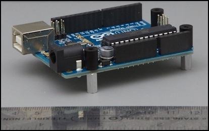
Uno R3 (with socketed chip, just behind front row of pin sockets)
Name: Uno R3
Cost: US$30
Processor: ATmega328
Voltage: 7-12V (5V operating)
Clock Speed: 16 MHz
Flash Memory: 32 KB
SRAM Memory: 2 KB
PWM Outputs: 6
Digital Pins: 14
Analog Pins: 6
USB: original (full size)
Pro Mini
There are several versions of the Mini, but the one I think is most of interest is the 5V Pro Mini (the 3V version is quite different). Unlike the others, Sparkfun has a version of this that sells for just US$10, and I’ve seen clones for half that. Note however that the Pro Mini lacks a USB connector, which can be added via external hardware (at an added cost) for programming. If you were going to be making a bunch of small controllers, this might be the one to use. It’s probably not worth the bother for just one.
For programing these via USB an FTDI cable or FTDI Basic Breakout board is required (the board adds reset-on-load functionality, so it is slightly preferable). You will need a 6-pin right-angle connector for connecting the cable or FTDI board to the mini while programming, but this can be held in place by finger pressure rather than soldered.
Note that while SparkFun’s Pro Mini uses the ATmega328, there are other, less expensive, versions available based on the ATmega168. These have less SRAM (1 KB instead of 2 KB) and less Flash (16 KB instead of 32 KB) and run at 8 MHz instead of 16 MHz. These limitations may make them less useful, but for many simple takes they are more than sufficient, and the cost savings can be substantial if you are using a lot of them.
As of 2016, I’m seeing a lot fewer of the 8 MHz models out there. Even the cheap ones seem to have mostly moved to the ATmega328.
I’m using these with my signal controller sketch.
Note that while the 5V Pro Mini is effectively the same as an Uno, it lacks headers (requiring all connections to be soldered) and while the per-pin output limit is still 40 mA, the Mini has a total power output limit of around 100 mA (the power regulator can handle 150 mA max, and about a third of that can be required by the board). If you bypass the regulator with an externally-regulated 5V supply, the total power limit increases from 150 mA to 200 mA (the same as an Uno). You have to watch your power budget more closely here.
Name: 5V Pro Mini (328)
Cost: US$10
Processor: ATmega328
Voltage: 7-12V (5V operating)
Clock Speed: 16 MHz
Flash Memory: 32 KB
SRAM Memory: 2 KB
PWM Outputs: 6
Digital Pins: 14
Analog Pins: 8
USB: none
Name: 5V Pro Mini (168)
Cost: US$8 (or less)
Processor: ATmega168
Voltage: 7-12V (5V operating)
Clock Speed: 8 MHz
Flash Memory: 16 KB
SRAM Memory: 1 KB
PWM Outputs: 6
Digital Pins: 14
Analog Pins: 8
USB: none
Leonardo and Micro
The Leonardo is a newer board (and it is discontinued as of 2016, but clones are still available), and it has a sibling in the Micro, which lacks the sockets for attaching things like motor shields, but could be wired directly to their pins if desired. Both of these have one very major change from the earlier boards, they use micro USB (not mini USB as used on many cameras, but the newer micro USB now starting to be found on some phones). This provides a connector that seems a bit flimsy (some people superglue them to the board just to be safe), but has a low profile, avoiding some of the problems that come from a large and bulky USB connector. From what I’ve read, the micro USB is supposed to be a better connector than the mini USB, less prone to making sporadic contact, or having the cable pop loose altogether.
The cable you need to use one of these with a normal computer USB is a “USB-A Male to Micro USB-B Male” cable.
The Micro, as you can see from the specifications below, is basically the Leonardo without the big power connector or shield sockets, but otherwise identical. And unlike the Pro Mini, it comes with USB (it also costs a lot more). The micro can also be bought without the pins, for soldering wires directly to it (but it has the same cost as the version with pins).
Surprisingly, these cost less than the Uno.
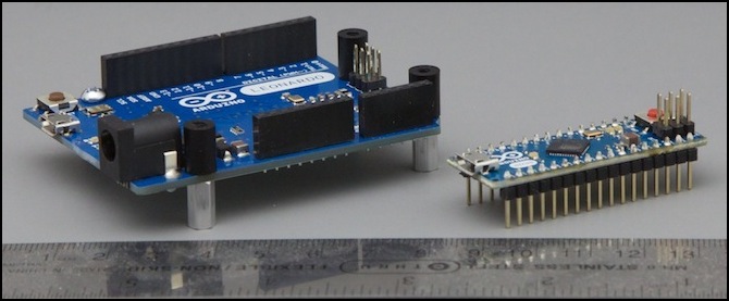
Leonardo (left) and Micro (right)
Name: Leonardo
Cost: US$25
Processor: ATmega32u4
Voltage: 7-12V (5V operating)
Clock Speed: 16 MHz
Flash Memory: 32 KB
SRAM Memory: 2.5 KB
PWM Outputs: 7
Digital Pins: 20
Analog Pins: 12
USB: micro USB
Name: Micro
Cost: US$25
Processor: ATmega32u4
Voltage: 7-12V (5V operating)
Clock Speed: 16 MHz
Flash Memory: 32 KB
SRAM Memory: 2.5 KB
PWM Outputs: 7
Digital Pins: 20
Analog Pins: 12
USB: micro USB
Mega 2560
There are a number of boards in the Mega family. The largest is the Mega 2560, now up to version 3 (I have the original version 1 I bought in 2011). Although it also has more pins, the big advantage of the Mega is more flash memory. This is handy when debugging programs, because typical debugging requires sticking lots of “print” commands in the code, and these take up quite a bit of space.
There are hardware differences I didn’t understand when I started, which make developing a program on a Mega for ultimate use on something like an Uno not quite straightforward, but the issues are easy enough to overcome with some thought. They mostly involve differences in how things like timers (important for PWM) work.
The older Mega, like mine, has a couple of capacitors (below, at the left) in exactly the wrong place. These prevent it from being used with newer shields that have two pins beyond the reset (IOREF and another) without cutting those pins. The current R3 version of the Mega does not.
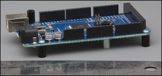
The original (non-R3) Mega 2560
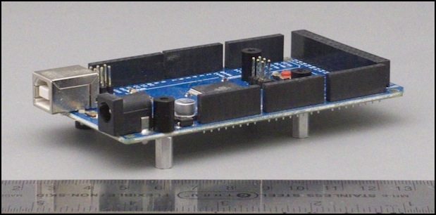
Mega 2560 R3
Name: Mega 2560 and Mega 2560 R3
Cost: US$60 officially, but I found an R3 in an official Arduino box (“made in Italy”) for $35 in a local shop
Processor: ATmega2560
Voltage: 7-12V (5V operating)
Clock Speed: 16 MHz
Flash Memory: 256 KB
SRAM Memory: 8 KB
PWM Outputs: 15
Digital Pins: 54
Analog Pins: 16
USB: original (full size)
Zero
The Arduino Zero is a new, and substantially different, model of Arduino. I don’t have one yet, so I’ve no photograph, but I’ve been playing with the very similar Adafruit Feather M0 so I’m familiar with them, and do plan to buy a Zero when I have some time. The Zero follows the Uno header layout, but note that shield compatibility is VERY limited due to the difference in voltages (see below).
What makes the Zero different is that it’s using a processor based on the ARM design, rather than the ATmega design. Specifically it has different assembly-language instructions (although you mostly won’t see that), a different pin interface (which may affect specialized programs), much more limited pin specifications (which will affect how you use it), significantly more memory, both SRAM and Flash, but no EEPROM at all, and a CPU that runs about three times as fast as an Uno’s.
Restrictions to be aware of:
- pins operate at 3.3V, applying 5V to them will likely damage the chip.
- power limits are just 7 mA per pin; these really should only be used to drive transistors.
- some specialized libraries won’t work due to the different pin interface design or other hardware issues
Name: Arduino Zero
Cost: US$55
Processor: Cortex ARM M0 (Atmel SAMD21G18 version)
Voltage: 3.3V (operating), 5.0 - ?? (input)
Clock Speed: 48 MHz
Flash Memory: 256KB
SRAM Memory: 32KB
EEPROM Memory: none
PWM Outputs: 18 (all but pins 2 and 7)
Digital Pins: 20
Analog Pins: 6 (only one is analog out)
USB: microUSB
Other Arduino-compatible Processors
As mentioned above, there are a number of systems on the market that are to greater or lesser degree “compatible” with the Arduino. I’m not going to mention simple clones here (there are too many), or even be exhaustive of all the interesting ones. I’m merely going to mention the models I’ve used, or may use, in my projects.
Feather M0
Adafruit makes a number of microcontrollers in their Feather line, using several different processors. I’ve only used the M0 models to date (and likely those are all that I will use, as they fit my needs). Feathers run the standard Arduino software for the most part, although you’ll need to install some Feather-specific libraries (follow the instructions in their tutorial for the model you use).
The Feather is about the same size as the Pro Mini, but more capable (and more expensive). Unlike the Pro Mini, it includes a microUSB interface for connecting it to a computer.
The Feather M0 uses the same Atmel SAMD21G18 chip as the Arduino Zero, so all of the concerns noted for that one (3.3V pins, low pin current, library and hardware compaibility) also apply.
Although the onboard regulator is rated for 500 mA, it really can’t produce much more than 300 mA without overheating (less if the source is more than 5V). Some models can use that much power from onboard circuits (e.g., the WiFi model, and possibly others), so powering other devices off the Feather should be done with care. Note that normal power use, even with a radio, is typically under 100 mA.
The Feather line is specifically aimed at “Internet of Things” applications, which means it has more sophisticated interfacing capabilities, including dual serial chips. Several models also include radios, either WiFi or short-range unlicensed-frequency radios for communicating with other IoT devices.
Adafruit also makes shields that match the shape of the Feather, called FeatherWings.
Although it’s not particularly relevant for most model railroad applications, the Feathers include circuitry for charging and running off an external lithium polymer battery. Note that LiPoly batteries (particularly cheap ones, but it happens even to good ones) have a bad habit of catching fire if damaged or improperly charged. If you use one, it’s probably a good idea to put a metal case around the feather and battery, just in case.
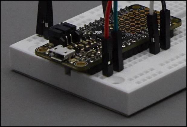
Feather M0 (Basic Proto model)
Name: multiple models
Cost: varies by model, US$20 to US$35
Processor: Cortex ARM M0 (Atmel SAMD21G18 version)
Voltage: 3.3V (operating), 5V (input; can be larger but there are issues)
Clock Speed: 48 MHz
Flash Memory: 256KB
SRAM Memory: 32KB
EEPROM Memory: none
PWM Outputs: varies by model (some pins used for other things)
Digital Pins: varies by model
Analog Pins: varies by model
USB: microUSB
Motor Shields
There is more than one kind of motor shield out there, and some are built for things like high-amperage motors (to run wheels on large robots, for example) or with extra features for more sophisticated servo-motor controls. To run a model train, a relatively low-power motor driving circuit is needed (at least as long as you are running N or HO scale, larger scales would need more). And many of the features for servo-motors are irrelevant.
Note: Although not listed here, there are also motor controller boards that aren’t shields, but could still be used with an Arduino simply by wiring them up. Often these work very similarly to a shield, since they’re usually all based on a small number of motor-control chips.
There is a surprisingly wide variety of motor shields available. All follow the basic pattern of one designed by the Arduino folks themselves, but oddly they don’t all use the same pins. It’s not too clear to me why they weren’t all done the same as far as basic connectivity like that, but it turns out to be a useful thing. All of the ones I’m looking at (and pretty much all of the rest) use versions of the L298 motor control chip, although in different cases for use with or without heat sinks. The L298 provides two motors, with each motor having one pin for PWM imput (effectively the speed control) and two pins for direction. The Ardumoto shield simplifies this to use only one pin for direction, which saves you a pair of pins if you want to use them for other things.
Heat and Power with Motor Controllers
This is a large enough problem, that I think I need to mention it separately. Motor controllers handle fairly large currents, over an amp in some cases even for the simple ones we’re looking at. These are not 100% efficient circuits, so some of that is lost as heat. Motor controllers without heat sinks are very limited in their ability to run continually. The actual rated current is going to be much larger than what you can achieve in practice for continuous use.
This doesn’t matter if you’re using the motor intermittently, for example to raise a bridge or open a door, or do some other non-repeating animation of a scene. It does matter if you try to run a train with it. Of course most trains normally run with much less than their worst-case power, so in a lot of situations you’ll likely be fine. But keep this in mind when evaluating motor controllers.
Arduino Motor Shield
Arduino has a reference design for the motor shield, which is/was available through Radio Shack (part 276-131). Or at least I could find them in my local stores; the website has no record of that part number. And the stores have been selling their remaining stock at clearance prices. The boxes I bought were marked for Arduino.cc, with the RS number on a white label stuck on the bottom of the box, but no printed-on Radio Shack info (RS usually gets their part numbers printed on the box for stuff they resell). Arduino’s version is up to its third revision and my board is marked “R3”, so they seem to be keeping the inventory current. While it claims “2A per motor”, it lacks any heat sink, which makes me doubt that claim rather strongly. No instructions were included in or on the box. The board is marked “made in Italy”.
Although originally priced at US$35, I’d seen them on clearance at several stores back in April for US$20, and on my most recent visits (July/August 2013) they were selling them for US$10 on a clearance table.
Because this is an official Arduino shield, it’s been updated to include the four new pins added to the “R3” generation of Arduino boards (SCL, SDA, IOREF and an unmarked pin), even though these do not appear to be required for this shield (however two are connected to the TinkerKit headers I’ll describe below). Those pins exist on both my Uno and Leonardo (both of those are “R3” versions also). However, on my mega (not an R3 version, the original Mega 2560), two of the pins were likely to short out against a metal cylinder on the Mega, so I won’t be testing this shield on that board.
The Arduino shield has both “brake” (8, 9) and “current sensing” (A0, A1) pins that aren’t required for what I’m doing (and aren’t provided for on most shields), but you can disable them by cutting traces on the board. There’s a fifth trace you can cut to isolate the board from the Vin pin. Why they didn’t use jumpers for this I have no clue; cutting traces is pretty crude for a hobbyist board you might want to re-use on multiple projects. The places where traces should be cut are well-marked, and should be easy to cut with a normal hobby razor knife.
In use, you can connect power to the motor shield, and not to the Arduino (the shield feeds the small amount needed to the Arduino). It would probably work with power connected to the Arduino 12V power jack equally well. Alternatively you can cut the trace to isolate Vin and power the shield and the Arduino separately (the local power input and Vin are wired together on the board). This is more elegant than what the Ardumoto below requires, since it allows boards above and below to still pass power through the Vin pin even while this shield is isolated, but it’s still more crude than moving jumpers.
The board includes some non-standard headers for use with TinkerKit switches and sensors. If you don’t use these, you should be able to stack another shield above this one, however I had problems with the relay shield I’m using. These use pins A2 and A3 (for sensors) and pins 5 and 6 (digital input/output, mainly for switches). The two TWI pins are for some kind of serial connection (they’re identified on the schematic as providing or reading SCL and SDA, which appear to be a serial interface added on “R3” Arduino boards).
You could use the TinkerKit connectors for switches to control the Arduino if you wanted. I think they’d be less useful for sensors due to the limited number of inputs (you can get a TinkerKit shield with more, but you’re using one analog pin per sensor this way). You can also use them yourself (the physical connectors are the little white ones used for 3-wire or 4-wire fans in PCs, although the way the wires are used is different).
The problem with the TinkerKit headers is that they stick up too far. While the Seeed v2 relay shield doesn’t appear to seat fully, it does seem to be making good contact. The Seed v1 relay shield, however, doesn’t seat as well. It appears to be making contact, but I’ll probably use some standoffs of bolts to screw it down to make sure it stays that way.
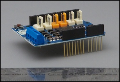
Arduino Motor Shield
Cost: US$35 (original in store price marked) - selling for $10 but marked “$20 clearance” (July 2013)
Motor A Pins: 3 (PWM), 12 (direction), 9 (brake), A0 (current sense)
Motor B Pins: 11(PWM), 13 (direction), 8 (brake), A1 (current sense)
Current: 600 mA total (without some kind of heat-sinking)
Note: I’m not sure if the $20 clearance ones are the R3 design or an older one, or if they are doing the clearance because it’s been discontinued. But if you are willing to use this model, it’s not a bad price for something you can pick up locally.
Ardumoto Shield
The Ardumoto Shield, from Sparkfun, is a simple version of a motor shield, and in some ways follows the Arduino design rather closely (it lacks the brake and current-sense pins), and uses the same version of the L298 chip in a normal IC case (no heatsink). You have to solder the headers (black boxes with pins) and power input and output (blue boxes) on yourself. But this also means it could be used with wires instead of pins, if for example you wanted to connect one to an Arduino Micro. When connected directly to an Arduino, it will draw motor power from the Arduino, unless you cut the Vin pin (as I did, you can see the truncated pin in the photo below) and add the third pair of blue connectors for the power input (front left in the photo).
Note that this is available with and without the headers (black rectangles with pins for stacking shields). However, in both cases you need to solder these on yourself, which isn’t hard but might be a surprise to some.
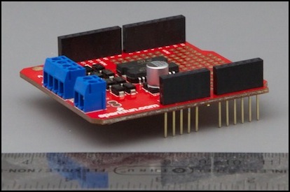
Ardumoto
Cost: US$30 (but you need to add the third pair of blue contacts) or US$25 (no connectors at all)
Motor A Pins: 3 (PWM), 12
Motor B Pins: 11(PWM), 13
Current: 600 mA total (without some kind of heat-sinking)
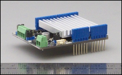
seeed studio V1
Seeed studios is a company in Shenzen, China, that makes a lot of hobbyist circuits, including Arduino shields. They have several motor shields, but the V1 Motor Shield is notable for being available via Radio Shack (part 276-242). As you can see from the photo, it has a very large heat sink (it uses the upright version of the L298 designed for use with a heat sink). Because this would prevent you from stacking another shield above it, the designers reused the edges of the board for a bunch of sensor connectors. These are for Grove sensors, and aren’t obviously useful in a model railroad application, so I’m not too interested in them. Note that the lack of headers also makes it very difficult to use this shield with controls (which somewhat defeats the purpose).
This is still available, although they also make a V2 shield. Coupled with a Leonardo, you have a US$40 system (if bought online), needing only a power supply to run some trains (well, that and some switches and the sensors if you want to have an automated system like what I’m planning). However, it doesn’t have headers that expose the pins, which makes connecting controls and sensors rather difficult. It’s a nice shield if all you want is motor control, or if you can use the attached Grove connections, but it’s of limited usefulness otherwise.
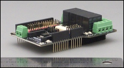
It is readily available, at least in the U.S., and for US$50 you can drop into your local Radio Shack and pick up this along with an Uno, which is also a good combination (that’s it on an Uno, on the right in the photo at the top of the post). And yes, it clears the bulky USB connector quite well, something I can’t say for the Ardumoto.
Note: the above Radio Shack notes are likely out of date, as they’re now several years old and Radio Shack has changed significantly in that time. I haven’t been back to check on Arduino’s, but their selection of all hobbyist materials seemed reduced the last time I was in one.
seeed studio V1
Cost: US$15 (online) or US$20 (in-store)
Motor A Pins: 9 (PWM), 8, 11
Motor B Pins: 10 (PWM), 12, 13
Current: 2 A
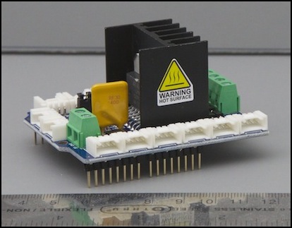
seeed studio V2
The V2 shield, which as far as I know is only available from them, meaning you’ll have to pay shipping from China, is functionally identical to the V1 as far as the motor part goes (it omits the Grove sensor sockets), but it has headers allowing another shield to be stacked above it, and it also has a low-profile heat sink that fits between the headers. I’d be a bit nervous at running high-current motors with some other shield stacked above it, but for low-current motors the shield will be an advantage (likely extending the life of the circuit board).
My version of this arrived with the headers in a plastic bag, so they need to be soldered on. This is handy if you want to use the shield wired to different Arduino outputs, but wasn’t mentioned on the product description (and the V1 motor shield came with headers attached). There are also some two-pin and three-pin jumper connectors that need to be soldered in the same manner.
Mine also died after a few hours of use. It might have been something I did, but I suspect either a component or design flaw (it seemed to be getting quite hot near one edge) related to the use of an external 12V supply.
One significant advantage of the V2 shield is that there is a jumper on the board to isolate it from the Vin pin. This means the motors can use a dedicated power supply without needing to cut traces or bend pins. As it turns out, what the jumper does is slightly different from what I expected, but still useful. What it does is allow you to either select the 5V logic voltage derived from the Arduino as the motor voltage, or isolate the shield and supply an external source (by removing the jumper). Since I need 12 volts anyway, that means I have to use a dedicated supply with this shield, but since I wanted to do that, I was okay with that. However as noted the shield died, and there are some cryptic comments on their site about use of the isolated power input that make me think I’m not alone in having problems. I’d avoid this until at least they clean up their documentation.
The other jumpers allow you to disable either (or both) of the motor outputs, meaning you need to put the jumpers on the correct pins or those won’t work.
seeed V2 Motor Shield with heat sink
seeed studio V2
Cost: US$20 (online) plus shipping (which can be substantial)
Motor A Pins: 9 (PWM), 8, 11
Motor B Pins: 10 (PWM), 12, 13
Current: 2 A
DFRobot Shield
Yet another shield is one made by DFRobot. It appears to also be resold by seeed studio as their “2A Motor Shield”. They make this in both 1A and 2A versions. Don’t confuse this with their “2A Dual Motor Controller”, which isn’t an Arduino shield. It has the advantage of being very well priced (the 1A model is the lowest cost). However the pin choices are problematic for use with the Uno (timer0 conflict, see below). Both 1A and 2A versions are stackable, and neither has a heat sink (which makes me wonder about the “2A” model’s real capacity).
The 1 Amp version uses an L293 motor control chip, rather than the more common L298, but aside from power limits they’re essentially identical. And the power needed for small trains is less than the limit, so the smaller shield is actually potentially a good choice, as long as you aren’t using an Uno). Paired with a Leonardo, you have a control system for US$39 before adding switches and sensors, which is pretty good. My big problem with this is that the pins it uses aren’t compatible with use of the seeed relay shield I want to use. I could find another relay shield, or make my own. The fact that the DFRobot motor shield only uses four pins, instead of six like the seeed motor shield, does make it attractive.
DFRobot is an overseas company, but has resellers in many countries (see their website for details).
No picture, as I didn’t buy one.
DFRobot Motor Shield
Cost: US$16 (2A) or US$14 (1A) - price may be higher from distributors
Motor A Pins: 6 (PWM), 7
Motor B Pins: 5 (PWM), 4
Current: 1A or 2 A
Rugged Circuits Motor Driver Shield
I don’t know much about this one, but it seems to follow the standard Arduino/Ardumoto pin assignments. The price is quite a good one on their Basic Motor Driver shield, although it lacks headers for stacking additional shields above it. They also make the Rugged Motor Driver shield with headers, a heat sink, and more protection circuitry, which is still cheaper than an Ardumoto. They also have a short explanation of why the “2 Amp” L298 motor driver chip that everyone (including them in the Basic model) use can’t really operate at 2 Amps per motor. Their numbers are a bit more optimistic than some others I’ve seen for what an Ardumoto can actually do, which suggests that their numbers for their own design may be as well.
Their better shield doesn’t use the L298 however, instead it’s using a pair of TI DRV8801 chips. I bought one of these (the “Rugged” version), but by the time it arrived I’d moved on to other project so it’s never been tested.
One very cool aspect of this board is that it’s designed so you can cut traces and run a short wire to use any four pins you want (well, two have to connect to things with PWM capability). This means that despite its use of standard pin assignments, it could be used with a Leonardo with very little work.
(no photo)
Rugged Circuits Basic Motor Driver Shield
Cost: US$16
Motor A Pins: 3 (PWM), 12
Motor B Pins: 11(PWM), 13
Current: 1,000 mA per motor (their number, may be optimistic)
Rugged Circuits Rugged Motor Driver Shield
Cost: US$24
Motor A Pins: 3 (PWM), 12
Motor B Pins: 11(PWM), 13
Current: 1,600 mA per motor (their number, may be optimistic)
Others
There are likely other shields. Some of the ones I’ve seen appear to be more purpose-built for servo motors or high-amperage motors. The list here are all the ones that seemed appropriate to my application that I found over the course of a couple of weeks of casual googling on the topic.
Relay Shields
A relay shield allows an Arduino to use a digital pin to switch an external wire between two alternatives. This can be used in a variety of ways, but I’ll be using them to switch a block (in the “track block” sense) between the motor outputs. In effect, this will let me create a two-cab control system for two blocks with one relay shield, which is what I need for my tram line project.
seeed relay shield V1
The V1 shield is rated to use a 9V supply, but can use up to 12V. It can be powered from the onboard jack or from two screw terminals, or via the Vin pin (all three wire together). There is no way to isolate the Vin pin from the on-board power terminals. It can draw up to 250 ma (the more of the four pins are high, the more it draws, since it’s energizing an electromagnet with each pin). Although this shield is still for sale at Radio Shack, it has been discontinued by the manufacturer. Presumably the ’shack will eventually get a supply of V2 shields, but I wouldn’t hold your breath waiting for that.
There are four relays, each is a single-pole, double-throw (SPDT) switch, meaning it can connect a COM pin to one of two outputs, labeled NC (Normally Closed) and NO (Normally Open). With the control pin LOW, the NC pin will be connected. Each relay can switch up to 3 Amps, and is rated for a service life of 100,000 throws. The three pins for each relay are on the green screw-terminal blocks, and the voltage through the relay is completely unrelated to the voltages on the shield. Thus the shield can use the normal Arduino power supply, regardless of what it is switching.
Note: Seeed rather unhelpfully deleted all text from their wiki regarding this shield when they discontinued it. The four pins control relays in the reverse order (pin 4 is relay #4 for terminals NC4 and NO4, pin 5 is relay #3, pin 6 is relay #2 and pin 7 is relay #1).
The relays used on my copy (HJR-4102-L-05V) are rated to handle 60VDC/120VAC, with 100K lifetime operating cycles. Switching time is 5ms to operate or release. And power consumption is 0.2 W (40 mA @ 5V) per relay. This is slightly more efficient than the version 2 model. Still, with all four thrown that’s 160 mA it will draw from the Arduino’s power supply unless you’ve wired up an external supply to the jack (and isolated Vin). Given the problems I had with external power on seeed’s motor shield (fried it), I’m somewhat dubious about external power here (and it doesn’t make me feel better that they removed that option from the V2 version).
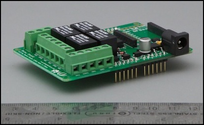
Seeed relay V1 (no headers, with power jack)
Seeed relay shield V1
Cost: US$ 20 (in-store), US$12 (online, but shipping charges will be high)
Pins: 4, 5, 6, 7
seeed relay shield V2
The V2 shield is similar to the V1 shield, but adds headers allowing other shields to be mounted above it, and removes the power connectors (it must be powered via Vin). I had planned to use this, but if I change to using the DFRobot motor shield the pins are incompatible, so I’d need to think of something else. One big advantage of this shield over the v1 is that on the v1, some pins from the relays stick down under the shield (only 1 mm or so), which could be very bad if you were switching higher voltages, and cause problems even for someone like me switching 12V. On the v2 shield, there’s a plastic plate below the underside of the shield to prevent any contact. This makes it a bit harder to mount (the attachments for the plastic bump into the headers and keep it from seating all the way down on R3 boards that have the additional pins), but it appears to work (I haven’t powered it up and tested it yet).
The relays used on my copy (HLS8L-DC5V-S-C) are rated to handle 30VDC/250VAC, with 100K lifetime operating cycles. Switching time is 10ms to operate or 5 ms to release. And power consumption is 0.36 W (71 mA @ 5V) per relay. This is slightly less efficient than the version 1 model, and also takes longer to apply the relay. With all four relays thrown, this will thus draw 284 mW from the Arduino power supply. Frankly, I’d rather not do that, and my earlier interest in this shield has cooled considerably.
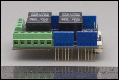
Seeed relay V2 (with headers, no power input)
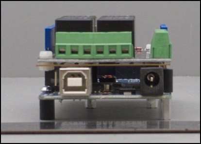
End view showing plastic shield under relay board (stacked on Mega 2560 R3)
Seeed relay shield V2
Cost: US$20 (online, but shipping charges will be high)
Pins: 4, 5, 6, 7
DFRobot Relay Shield V2.1
The DFRobot shield appears to be a good choice, except for some possible conflicts in pin usage. It supports an external power supply, and has test buttons for each relay. Oddly, the default pins have a conflict with the DFRobot Motor Shield (pin 7 is used by both). It also has a pin conflict with the seeed motor shields (pins 8 and 10). The shield is stackable.
While the shield has default control pins (listed below), you can change each of these individually to use any pin by removing a jumper and running a wire between two posts on the board. These are ordinary square jumper posts, slightly larger than standard Arduino header pins, but a socketed jumper wire (like these) would probably work. I haven’t tried that though.
This claims to use the same HJR-4102 relay as the seed V1 shield, although it wasn’t clear from the documentation if they used the low-power “L” model. However, when mine arrived it was equipped with JZC-32F relays (5V, non-sensitive form). These are rated for 90 mA draw each, so the power supply would need to provide at least 360 mA @ 5V (1.8 Watts), so use of an external supply is really mandatory with this.
The shield has a pair of screw terminals allowing a second power supply to be connected for use by the relay servos. If this isn’t used, the relays will draw power from the Arduino’s power supply (typical of relay shields), but if a 9V supply (rated for at least 1.8W or 200 mA @ 9V, and a bit more to cover loss in the regulator) is connected to the servo jacks, that will be used instead to drive the relays. This is an advantage over the seeed shield.
This is a long shield. Mounted directly above a Mega 2560 it will block access to the pins across the end of the shield (22 to 53), as well as analog pins A6 to A15 on one side, and digital pins 14 to 21 on the other (meaning you end up with the same number of pins as on an Uno).
DFRobot V2.1
DFRobot Relay Shield V2.1
Cost: US$14
Pins: 2, 7, 8, 10 (but can be changed)
