


Signaling with Arduino
It seems that I can never resist the impulse to make things more complicated. While working on my Arduino sketch (program) for the Tram Controller, the thought struck me that I could add signals at the stations to tell the fictive operators of the trams when it was safe to leave. These would be “starting signals” in typical Japanese practice, and only require two LEDs, red and green. Of course I’m all out of pins, and the only step up from the Uno, which has 20 pins (14 digital, 6 analog) is the Mega with a whopping 70 pins (54 digital, 16 analog).
Note: if you read Arduino websites, it might seem like I’ve got those numbers wrong, or that the Leonardo falls in between with 26 pins, but the way they describe them counts pins that can be both analog and digital twice. My counts reflect the actual headers on the boards. The Leonardo has the same number as the Uno, it’s just that six of them can act as digital or analog while on the Uno, the six analog pins are analog-only (or at least that’s what the documentation implies they do; I haven’t tested it). In any case, I have one of each and counted the actual pin headers.
So lets assume I don’t mind spending a bit more for a Mega (and I already have one anyway), what does it take to add signaling? Well, that depends on the signal. First, because the Arduino pins are limited to 40 mA, if I want to drive signals without added hardware, I need to use LED-based signals, as even small bulbs typically require 60 mA or more (there could be ways to cheat on that with pulsed power, but it’s probably a bit risky and I’m not going to try; LEDs are preferable to bulbs for other reasons like lifespan and size anyway).
For additional info on this topic, see my Using LEDs with Arduino page.
Signals, Resistors and Power
Let’s take a look at what I need to drive. I’m not going to try converting signals from a Japanese manufacturer for this. For one thing, I don’t need anything more than a two-light signal on a mast, and Japanese two-light signals look almost exactly like North American ones. Secondly, I’d pay more for Tomix signals (around US$35 before shipping) and have to do extra work to convert them, and I’d end up with signals that I don’t think look as good.
I have a couple of choices for N-scale brass LED signals with red and greed lights on a single head: NJ International and Tomar. NJI has apparently recently started making LED signals, but these can’t be found at all stores yet. Their #2002 (black mast and head) or #2004 (silver mast and head) are what I need, both listing for US$16. A second option is the Tomar N-857 (silver), which lists for US$23. I could also buy the parts and build my own, and probably save half the cost or more, but I’m far too lazy for that.
Note: all of what I’m writing here applies to HO-scale signals also. They’re more likely to use 20 mA LEDs than 10 mA SMD LEDs, but otherwise their requirements are the same.
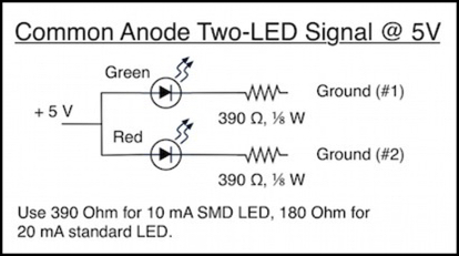
Actual wiring info or specifications for the signals is hard to come by although Digitrax’s documentation implies that Tomar signals are wired with a “common anode”, meaning the positive sides are tied together and three wires exit the signal mast. Neither vendor appears to actually document them, although examples of both NJI and Tomar I have were both wired common anode with three color-coded wires leaving the mast (red, green and a third color for the common). The Tomar signals came without resistors, the NJI had pre-soldered 1000 Ohm ones (for 12V use), which I had to remove. Those resistors imply NJI is using low-current (10 mA) SMD LEDs, and they’re physically small enough that this seems likely.
Since the Arduino uses 5 V power, I need to adjust the voltage down from that to a safe level. Taking the worst-case (smallest) voltage drop of a LED of these colors as 1.6 V, a 180 Ohm, one-eighth Watt resistor will do for 20 mA, and a 390 Ohm resistor would be needed for 10 mA (both would be 1/8 Watt versions). If the LEDs were larger versions with 3 V forward voltage, I could probably get by with 100 Ohms (or even less). To be safe, I should use the 390 Ohm resistor unless I’m sure (and since the signals are undocumented, I’m not sure).
Rather than get embroiled in that aspect, I used some Radio Shack LEDs on a breadboard for testing (they’re cheaper too, if I get something wrong and fry the lot of them, although so far I haven’t had any problems).
Note: when I get to pulsed power below, you might think that changes the resistance needed. It does not. Resistors limit voltage in a LED circuit, and pulsed power reduces “power” and average voltage which maintaining the same peak voltage. You need the resistance to limit the peak voltage to avoid stressing the semiconductor junction inside the LED. It might not be stressed as much if the power is on briefly with pauses between, but it will still be stressed and over time that could cause premature failure. Some online information I’ve seen suggests that it’s okay to reduce the LED’s resistor sizes with pulsed power, but I’m going to be cautious. I’d rather not have a bunch of expensive signals fail on me.
Now I could simply connect the + line to a 5V source and #1 and #2 to a pair of pins. With a pin HIGH the LED is off, set LOW it will be lit. The first problem is that this is drawing 10 - 20 mA off the positive line, and if I’m using the Arduino as the source I couldn’t do more than a couple of LEDs. I could avoid that by tapping power off the supply feeding the Arduino external to it, but then I wouldn’t be able to just plug the power supply into the Arduino; I’d need something between them. The second problem is that this uses two pins per signal (one per LED), which is a trifle excessive.
Other Solutions
One common method for dealing with LEDs is to use a driver chip. Arduino has an example page describing use of a LED Driver chip if you want to go this route. One thing I don’t like about this is it takes time to signal the chip, and you have to use delays to ensure precise timing of that signal, so you lose something more than 560 microseconds each time you want to change which LEDs are lit. That may not seem like much, and in many cases it won’t be, but if you need to change them a lot or you’re doing other things that need time, it adds up.
The solution I’ll describe below uses 12 microseconds of processing time once every 1,000 microseconds to drive twenty LEDs. My method could still use more time overall since you’re unlikely to change the state of the LEDs too often, but it’s time that’s evenly distributed in small amounts, and that’s an important characteristic when you want the program to be off doing other things most of the time.
Multiplexing and Charlieplexing
Now my solution is essentially the same one I’m using for my sensors: multiplex them and use pulsed power to activate them, so I’m really only drawing power for one (or a few) at a time, but thanks to the persistence of vision it looks like all of the “lit” LEDs are lit simultaneously.
My first thought was that I’d somehow need to arrange pins to form a grid, and activate two pins to light the LED at the intersection of the grid lines. For ten signals with twenty LEDs this would need a 5x4 grid and nine pins, which is much less than 20, but it’s still a lot for an Arduino. Fortunately I did some reading before I got too far, and discovered Charlieplexing.
It’s a silly name (the technique was discovered by a guy named Charlie), but a great concept. It depends on the fact that a microcontroller pin has three states, high (+5V), low (grounded) or off (aka INPUT, where it’s grounded through a 10K Ohm+ resistor). In the INPUT state extremely little current will flow through it, and it can be treated as effectively being off rather than grounded.
There are a couple of ways to think about how you use this with LEDs. The one most typically used is to treat each pair of LEDs as a reversed pair, with pin A connected to the anode of one LED and the cathode of the other, and pin B the reverse of that. To light one LED you make pin A high and pin B low, to light the other make B high and A low, and if both are low or high the LED is off. It’s also off if either (or both) pins are in INPUT state. Then you wire them up in groups such that no two LEDs share the same (+) and (-) pins in the same direction. The first couple of times I tried to figure out what that meant and how to extend it beyond three pins and six LEDs while using common anode wiring, my head exploded.
Then I took a long look at the three-pin example (see this wikipedia article if you want to see that diagram). And I realized that another way to look at what it was doing was to think of it as working with three pairs of LEDs wired in common anode (or common cathode), where pin A goes to anode, and B and C go to the two cathodes (and you vary which pins are A, B and C for each additional set of LEDs). With that it was easy for me to visualize the structure in a way that worked with common-anode wired LED pairs in signals.
The basic idea is that N pins let you drive N sets of N-1 LEDs. Signals that are wired with two LEDs on a common line are implicitly sets of 2 LEDs, so they work well with 3 pins. But you can join two signals into a set of four LEDs with a common anode, and those work well with 5 pins. In fact, this kind of signal is a natural fit for odd numbered counts of pins.
You could do something similar with three-color signals with three LEDs: each signal is a set of three, so four pins give you four signals (four sets of three) and joining two signals gives you sets of six LEDs, so seven pins would give you seven sets (fourteen signals, 42 LEDs total).
Here’s an example of the 5 pin, 10 signal, twenty LED design:
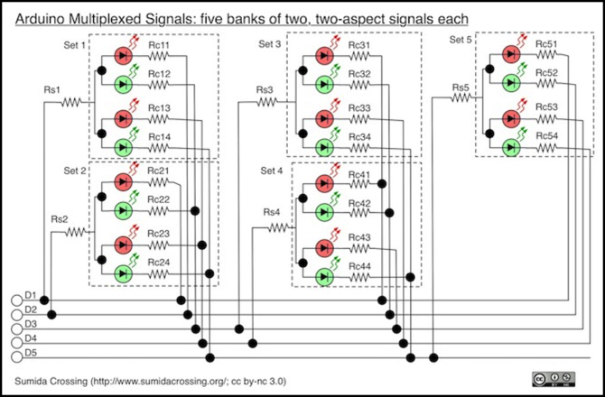
Each dotted-line box surrounds one set of common-anode LEDs, which consists of two red/green signals with their anodes tied together. Set 1 (top left) uses pin D1 as its HIGH line and pins D2 to D5 as it’s LOW lines. If D1 is high, setting any other pin to LOW will light the associated LED in set 1. If D1 is LOW (as it would be, for example, to light the first LED in the second set using D2 as the HIGH line) none of the LEDs in the first set will light as there’s no supply voltage for them. Each set connects it’s LOW side to the four pins not used for its HIGH side. When a pin isn’t needed as LOW or HIGH, it’s placed in INPUT state. And at any given instant, only one pin should be HIGH and one LOW (actually, you could be a bit more efficient if you want to light two LEDs in the same set and turn both their LOW pins on; you just can’t turn a second HIGH pin on without inadvertently lighting multiple LEDs you didn’t intend to light).
You’ll notice that there are a lot of resistors here. That’s because of the common anode wiring. Because it’s never a good idea for two LEDs that will be lit together to share a resistor, I put resistors on each LED, and because of the common anode wiring I had to put them on the cathode (negative) side of the LED. The problem with that was that the Arduino pins in LOW state aren’t a perfect ground, because of internal resistance in the Arduino circuitry. This caused the cathode voltage to be above zero, which caused current to recirculate from the cathode side of a lit LED to the anode of another bank, and there was enough current to light the LED dimly. For the LEDs I was testing with, I needed at least 150 Ohms of resistance. I put a 100 Ohm resistor on each anode (the RsN resistors) and a 68 Ohm resistor on each cathode (the RcNN resistors) and this worked quite well without any LEDs lighting unexpectedly.
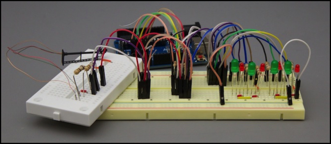
I was using Radio Shack 276-0026 (3mm low-intensity RED, 3 V, 15 mA) and 276-0022 (5mm green, 3V, 20 mA LEDs) for my test, but to ensure that I could mix LEDs I added in an NJI signal (which almost certainly isn’t using LEDs with the same specifications) with the same resistors, and the circuit continued to work as expected. The NJI signal was a bit dim, suggesting that it needed smaller resistors; I’ll experiment with that later. The photo at the top of the post shows my 8-LED test board with the NJI signal on a second breadboard added as the fifth signal (wired as set 3, signal 1).
Note: if you do common cathode wiring, LOW and HIGH in the above example would be swapped because the cathode (LOW) pin controls the set of LEDs, and the anode (HIGH) pin selects individual members of the set.
My actual tram line won’t need ten signals. All it needs is one starting signal at each station track (four total), and the urban tram line (which has a longer double-track section) can add two station-entry signals on approach to the two end stations, for six. You might think that would require fewer than five pins, but it doesn’t.
With this method, if I want to use more than three signals and less than ten, I still need to use five pins, because of the requirement to make sets multiples of two LEDs. If I hand-built my own signals and didn’t use common wiring, I could arrange the LEDs in arbitrary sets and use four pins for up to six two-LED signals (arranged as four sets of thee LEDs). But using commercial signals, I’m limited to sets that are multiples of two LEDs due to the use of common anode wiring inside the signal mast.
Strobing the Pins
In the above example, I have four LEDs per anode pin and twenty LEDs total. Assuming I use the NJI signals and that they are 10 mA per LED, I could potentially light all ten signals (one LED lit per signal) as the aggregate power need would be only 100 mA. Still, that’s cutting it a bit tight, and I could have issues if other pins on the I/O set of the chip were using power, or if the signals need more than 10 mA per LED.
What I’m going to do then, is take advantage of the persistence of vision and pulse power to the lit LEDs in turn, so that I have no more than one being powered at a time. To keep the refresh interval below 20 msec (to avoid visible flicker) I’ll assume no LED is lit for more than two msec (and that only one LED per signal is lit). This makes the signal a bit dim, but it’s still visibly on and that’s really all I need. For my testing, I actually used 1 msec and scanned through all twenty LEDs even though half would be off all the time, just to keep the proof-of-concept program simple.
The code to do this isn’t really very complicated, I just need to ensure that my main loop cycles 1 millisecond or less, and each time around I check to see if it’s been a millisecond since the last time I changed the state of a LED, and if so I turn off the lit LED and turn on the next one that needs to be lit. With twenty LEDs checked one at a time, every 20 msec I’ll refresh each lit LED (with six signals, I could potentially refresh every 6 msec with a bit more complexity in the code, which is even better).
It’s easier to show this than to tell it, so I’ve constructed a sample sketch (which I used for testing) and that’s available (download it here) if you want to see it (as with all of my code, it’s public domain so you can use it to make your own programs).
In Summary
There are easier was to drive LEDs, it’s true. But this method works, and it works in such a way that I can easily integrate it in the Tram Controller program without affecting how I do timing for other things there. And it has the benefit of being power-efficient (always a good thing) and relatively simple (the which wire goes where part isn’t trivial, but it’s not really hard either). I will have to step up to the Mega for my controller, as I just can’t free up five pins, no matter what I do. But while that adds US$30 to the total cost, it’s an acceptable price to add signal control. The signals, after all, will add about US$100 to the 1.5 meter layout, or US$130 if I put them on the Urban Tram line.
Other Uses
The signal management code just takes a list of LEDs, and lights them or leaves them dark depending on an array listing the state of each. In my final program, I’ll set those states based on occupancy detectors and other inputs. But that doesn’t have to be all that’s done. It would be easy enough to connect a couple of pins to a control panel and allow a CTC operator to set signals (with detectors overriding that control as per usual signaling practice), or you could add other capabilities to the Arduino to let it communicate with other Arduinos via a serial line to construct a larger system than will fit in one Arduino.
And if you want computer control you can use CMRI over a serial line (using this library) or you could use a CAN-BUS shield (like this one) once NMRANet gets a bit more polished and someone has a library to support it on the Arduino (I’m not aware of one today, although they do have some Arduino support for other hardware you could probably adapt if you’re a programmer, see this page). Actually, you don’t even need the shield, as described on this site.
You don’t need to limit yourself to signals either, the code can just as easily be used for traffic lights at an intersection or anything else with a bunch of LEDs that need to change their state either on timers or due to external inputs, or both.