


Model Railroad Wire Ampacity
The ability of a wire to carry current without failure, known as its Ampere Capacity or Ampacity, depends on a number of factors including the diameter, voltage, frequency, composition, insulation and environment. Ultimately this is related to the heat produced by current flowing through the wire, and the wire’s ability to dissipate that heat. More heat than can be dissipated will raise the temperature, until the wire or the insulation melts, or until objects adjacent to the wire reach their ignition point and catch fire. Wire in open air dissipates heat more efficiently than wire in a closed space. The type of electrical insulation used also is a significant factor.
One note of caution: I’m not an electrical engineer, or any kind of electrical expert. I’m a hobbyist with some technical knowledge (just enough to hurt myself). What I’m presenting here is my current “best guess”, and what I’ll use for my own model railroad layout. That doesn’t mean that it’s right, and it’s quite possible even with my numbers that a wire could get hot enough to damage a model. Follow your local electrical codes for anything those codes cover if they are more restrictive than what’s presented here, and even if low-voltage wire is exempt use them as a guide to maximum “safe” current levels. And if in doubt, use a larger wire.
See the Derivation page for further information about these tables, and where their data came from. If you believe any of this material is in error, please send me an email at the address on the About the Site page.
Application
A model railroad uses wire to provide electricity to trains and to scenic elements (building lighting, for example). This is typically low-voltage DC, but may also be Digital Command Control (DCC), which is a form of AC using variable frequency signals ranging from about 100 Hz to about 10,204 Hz (the normal maximum is around 8kHz). Motor decoders used with DCC will also use Pulse-Width Modulation (PWM) to control the motor, another form of variable-frequency AC using maximum frequencies around 15,000 - 30,000 Hz.
Wire size here is given in American Wire Gauge (AWG), but this measure isn’t used in the rest of the world. In Europe cross-sectional area (or in some cases number of strands and diameter of each) is used. I haven’t been able to find a metric ampacity table (they’re likely out there, but in some language other than English so Google doesn’t find them when I search). However, there are conversion tables (like this one), and I’ve used that to get the mm2 numbers listed below. Wikipedia’s AWG entry also includes an ampacity table with the metric equivalences, but it doesn’t include the ampacity measure for smaller gauges.
Model Railroad Ampacity Tables
Electrical standards and safety organizations publish ratings for wires based on their size (gauge, or cross-section area), such as those in the National Electrical Code (NEC) published by the National Fire Prevention Agency (NFPA) in the U.S. Ampacity tables (like this one) describe the allowed minimum size of wire for a given current under two conditions: in open air, and in a confined space, given a number of assumptions, one of which is that wire can be allowed to heat to 90°C (194°F), close to the melting point of typical PVC insulation (sometimes 75°C is used instead). These tables are designed for household or high-current AC at standard frequencies, and are rated to avoid fires due to overloaded wiring as well as to limit voltage drop under typical conditions to an acceptable amount. They are the right thing to use for power wiring, and reasonable to use for layout power bus wires and similar.
But they aren’t necessarily a good description of how wire works in DCC applications due to the much higher frequencies in use there, and some of their assumptions may not be desirable. For instance, styrene melts at about 100°C, but it can deform at lower temperatures. Allowing a wire embedded in a plastic model to reach 90°C is probably not a good idea. Also, these tables typically assume an environment of 20°C, or 68°F (sometimes 25°C, or 77°F), and wire in very warm environments can’t carry as much current as wire in a cooler environment would before it reaches the same temperature.
I’m going to define my own tables, specific to the usages of model railroading, and those will go here. At present the tables below are somewhat incomplete, being based on existing tables or other information which has not been fully adapted to this purpose.
Normal Wire
You can find a number of Ampacity tables googling around the web. They’re a good starting point. Based on a number of things I’ve read, it would appear that derating allowed current by 20% will limit wire temperatures to 75°C (167°F), which would provide for a good safety margin within a plastic model and I’ve illustrated that below.
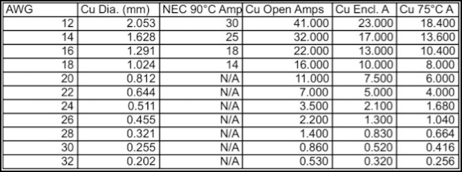
In the table below, the NEC safety rating for AC power wiring is listed to show how it differs from the simple ampacity numbers found in some tables. Ampacity is listed for three additional situations: “Cu Open Amps” is open-air wiring (e.g., a power bus hung beneath a layout), “Cu Encl A” is an enclosed rating for the standard 90°C value (applicable to wires inside a control panel or similar) and “Cu 75°C A” is a derated number reflecting the approximate limits for a wire not to exceed 75°C in a 20°C environment, reflective of wire used inside an enclosed styrene model or structure.
The “Cu 75°C A” number falls in the middle between the baseline numbers from the original table (which I suspect are overly optimistic) and the magnet wire table below (which I suspect is overly conservative). For the time being, I’m going to use that column as my guide for use. And that tells me I could use 30ga wire with no problems on my decoders, and might even be able to use 32ga. To be sure, I’ll stick with 30ga.
Normal (stranded) Wire Ampacity
For another perspective, a chart from a manufacturer of hook-up wire (I’ve seen similar tables from other cable manufacturers) shows that 28ga wire in open air at 25°C can carry about 2.2 Amps with a 35°C temperature rise above ambient (60°C or 140°F), but only about 0.2 Amps with a 10°C rise (35°C or 95°F). That’s so completely different from the above that it makes me wonder just what assumptions are being used by both of them.
Magnet Wire Ampacity
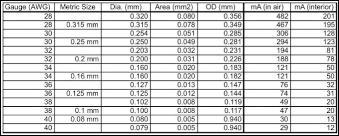
Magnet wire is available in larger sizes, but as this is solid core wire with expensive, high-performance, insulation, it is really only applicable to model railroading in smaller sizes, where it can be used for LED signal heads, structural lighting, or perhaps decoder installs where space is very constrained. In the table below, OD is the diameter of the wire plus insulation, “mA (in air)” is applicable where the wire is not constrained, and “mA (interior)” is a worst-case number for wire that is unable to exchange heat with surrounding air (and the number here is probably further derated for use in a magnet, so the real “interior” number may not be this low).
This table appears to be very conservative, and I’m not sure exactly why. It was derived from some amps/square-meter numbers found online for “typical” magnet wire, and I suspect it assumes use in an actual magnet, where wires are tightly packed and heating each other. That makes it much more conservative than the general table up above.
This suggests that for a single colored LED (30mA), wire down to 36ga is safe in any application, and wire down to 40ga may be safe if the wire is exposed. For decoder use, however, even 30ga is likely to be problematic in a tightly constrained space if a motor is stalled, although it may otherwise be adequate. Again, the table up above may provide a better guide, although it may be overly optimistic. Note than an SMD LED draws about 5-7mA of power, so even 40ga should be safe for an application using one of those even if the wire is enclosed, such as in a signal mast. However a signal using conventional 1.5mm LEDs (20mA to 30mA) should probably use 36ga, although 38ga may well be adequate.
Magnet Wire Ampacity and Specifications
Voltage Drop
For large-scale wiring, loss of power in long runs of small wire leads to a drop in the effective voltage delivered to the load. For short track feeders this doesn’t matter much, and for the low currents of smaller-scale models on DC, it would only be an issue with really long wires. But for the high currents found in DCC bus wiring, or for the small wires found in DCC decoder installs, voltage loss is a more significant concern. Distances in the table below are based on total conductor length assuming two conductors (e.g., a 5m bus extends 5m from origin to farthest point, and has 10m of total wire, 5 out and 5 back).
Note: as discussed on the Derivation page, there’s some additional loss on DCC with larger gauge wires due to the “skin effect”, but this only becomes even slightly significant at 12ga or larger wires, and in the worst-case of 10Amps on 10ga wire amounts to less than 1% of total voltage (an additional 0.8V lost to be precise). For that reason, although the following tables are computed for DC, they can be applied to DCC as well.
How much loss is too much? That’s going to vary, but in the following tables, color-coding is performed based on a desired maximum level of loss and a worst-case maximum acceptable loss. See the Derivation page for the reasoning behind the numbers.
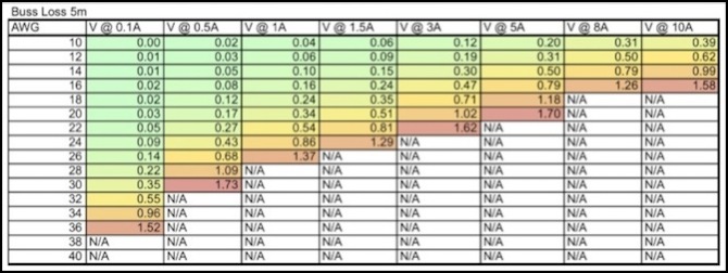
For bus loss, color-coding is based on a 12V supply with green being below 5% loss (0.6V) and values above 15% (1.8V) being unacceptable.
Assuming you limit your track feeder bus to 10 linear meters (about 33 feet) and place the command station in the middle, so that maximum distance from the station is 5m (~16.5’) the following table shows the voltage lost in such a bus based on simple DC resistance adjusted for wire temperature of 50°C.
Note: the following tables have not yet been corrected for maximum acceptable ampacity due to heating effects. Do not exceed the numbers in the Ampacity tables above regardless of the ratings shown here.
Voltage Loss in a Track Bus based on Load
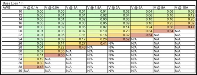
Track feeders are shorter, and typically much smaller than the track bus. I’m assuming no more than 2% loss (again on 12V) here is desirable, with 5% the maximum acceptable. Less than 2% is color-coded green, with more than 5% marked “N/A”. Other conditions as above. The table below is for 1m (39 inch) feeders, which assumes some under-table wiring to circuit breakers and occupancy detectors. For shorter wires multiply by the length in inches over 39 (e.g., a 12-inch, 22ga feeder carrying 3A will have 0.32*(12/39)=0.098V loss). The dark-outline box around 24 gauge up to 3A is for Kato Unitrack feeders (Unitrack is rated to 3A maximum).
Voltage Loss in Feeder Wires based on Load
See also the discussion on my DCC Layout Power Wiring page for a more in-depth discussion of bus wiring and desired wire gauge for it.
Turning to decoders, the picture is very different. A typical motor decoder uses less than 0.5 Amps in N-scale, although some older ones can be larger. A function-only decoder operating only a few LEDs or one bulb at a time could use only a tenth of an Amp. These can use very small wire, and even there the voltage loss is miniscule over the short lengths of wire used inside a locomotive or motor car.
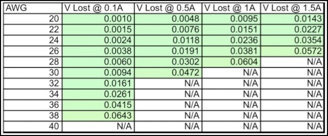
Voltage Loss in 6” (15cm)
Again, this is a very optimistic table; I haven’t corrected for all of the factors that could affect maximum current. While this says 30ga wire is usable for a 0.5A decoder, I’m deeply suspicious that this is below the desirable size under some circumstances, despite the fact that many decoders come with 30ga wire, and many people have made use of it. The ampacity table, which is the source of the red-marked entries here, suggests that with derating, 30ga wire is suitable for 416mA, which is still likely to be fine for a typical N-scale decoder, but is below the 500mA here. Again this is a placeholder table until I can make a better one.
Another case is power supply for accessories, building lighting, and similar things. Here, small diameter wire is desirable for ease of installation, but wire runs can be much longer, and thus loss will be higher. Here I’ve computed loss for ten feet (3m) of wire, a reasonable length running around a layout. Loss approaches 10% at the ampacity limit of the wire, so there’s a greater advantage to the use of larger diameter wires than current alone would imply.
Note that wires could be much longer, but in that case it probably makes sense to use a large-gauge set of wires to get power to an area on the layout, and then smaller wires between accessories or buildings in that area.
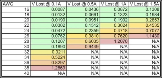
Voltage Loss in 10’ (3m)
Voltage Loss
For very large current over long wires in layout wiring, the amount of power lost in a wire may be more of a limiting factor than heating at the voltages typical of a model railroad, particularly for layout bus wiring.
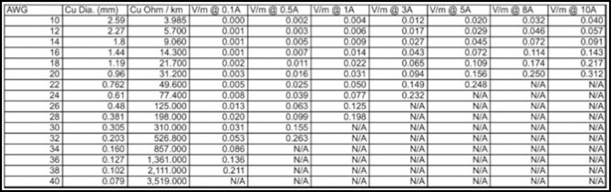
Voltage Loss per Meter at different Amperages
The above table shows the voltage lost in one meter of a pure copper conductor at various current levels. As presently written, it is based on simple resistance and does not correct for skin effect or temperature-based alterations to wire capacity. When applying this to a bus or model wiring, keep in mind that you need to count both wires, so a 30’ power bus is 18.2m, not 9.1m.
