


DCC Basics: Power
This page is an overview of how a layout using DCC gets power to run the trains to the trains. Additionally it covers several useful related topics, including how to measure voltage in a DCC layout, how much is needed, and how DCC differs from DC.
For a more in-depth discussion, see my Power for Trains page, and for information about wiring a layout for DCC see my DCC Layout Wiring page as well as the excellent Wiring for DCC website, which covers far more topics, and in more depth, than I ever could.
Voltage, Current and Trains
In a DC-powered model railroad, the motor on a train is directly controlled by a “power pack”, which puts a variable DC voltage onto the rails. This varies from 0 to about 16 volts typically, and will be “positive” (right rail is higher voltage than left rail) when the locomotive is to move forwards and “negative” (right rail is lower voltage) when it is to move backwards.
DCC is, in the end, just a way to get DC power to the motor on a train. It does this by mixing that power with control information, which the decoder on the train will sort out, providing variable DC power to the motor depending on what the control information indicates is desired. But the maximum power the decoder can provide to the motor is ultimately limited by the power on the rails, and more specifically, the voltage. And without adequate voltage, a train won’t run well, if at all. However, too much can be just as bad.
Command and Power
In DCC, commands are processed by a Command Station to put them into the form used by DCC decoders on trains. These are sent over a Power Station Interface (which may exist only within a device, or be externally accessible) to a Power Station that mixes commands with power, and puts the results out as a pair of “track” outputs (often labeled Rail A and Rail B, although the names don’t matter except when doing things like reversing sections, see Layout Wiring for more on this). On systems that also externalize the power station interface external power stations, called Boosters, can be added to provide more power. Each power station has to connect to separate parts of the layout, with both rails insulated between those “power districts”, but trains can move from one to the other.
It’s the output of the power station that runs trains. Each power station has a rating in Amps which identifies how many trains it can run. A typical N-scale loco may use around 1/8th of an Amp (125 mA) so a three-Amp supply could run as many as 24 trains. Some larger or older trains may use a half-amp or even more than an amp. And trains with lighting or sound will need more power than those without.
Power stations also have a rating in volts, with 12 volts being typical for N-scale, and 14-16 volts being typical for HO (and usually acceptable for N-scale). Some of that voltage gets lost on the way to the train, in wiring and track, and some of the power (amps) is similarly lost although rarely enough to impair operations. The maximum normal voltage in a DCC system is 22 volts, but that may be too much for small trains, particularly older ones with lighting that have been converted to DCC.
For more about command stations, see the Control Systems page.
How Much Voltage?
Per the NMRA standards, a decoder must work on 7 volts (measured as described below, which I’ll call “7 volts DCC” to distinguish it from simple DC voltage). However, voltage is lost in track, wires, and connections (like rail joiners), so the command station has to put out more voltage for the system to work reliably. The minimum voltage a command station should put out is 12 volts DCC. Most common ones will put out 14 to 15 volts DCC. A few put out more (those designed for G-scale tend to use 20 volts or more). The maximum a command station is supposed to provide is 22 volts DCC, but that’s enough to cause problems for some models. Some command stations include a way to switch the voltage.
If you have a choice of voltages, N-scale is probably best off with 12 volts DCC, but many common systems used for N-scale provide 14 volts DCC with no apparent ill effect. Most systems intended for HO provide between 14 and 15 volts DCC (at least one used 18 volts DCC, although it may no longer be made).
Voltage at the track can easily be 2 volts less, and voltage produced by a command station will vary with the number of trains running. A “12 volt DCC” command station could easily put out more like 13 volts DCC with no trains at the output terminals of the command station, and with trains running voltage on the track could be closer to 10 volts DCC. Don’t sweat the details if you’re a volt or two either way from what you think is the ideal voltage.
Measuring DCC Voltage
First the fun part: there’s more than one kind of voltage. DC is easy: you have a positive or negative voltage relative to some reference (often called “ground” even when it isn’t tied to a real earth ground). Any multimeter with a DC scale will read DC volts correctly.
The normal measure of a varying voltage (e.g., AC wall current) is the RMS (Root Mean Square) voltage. This is a measure of voltage such that the power (current times RMS voltage) would be equivalent to an identical DC voltage with the same current. But since AC is typically a sine wave, this means that the peak voltage (which is very short-lived) is actually higher than the RMS voltage. A good multimeter with an AC scale (called a “true RMS” meter) should read RMS voltages even for waveforms that aren’t sine waves, within limits, but cheaper meters (and reportedly this includes some marked “true RMS”) will only give RMS voltage for sine wave inputs (where RMS voltage is 0.707 x peak voltage) or things that look similar to sine waves. My experience suggests that DCC waveforms are far enough from sine waves that even “true RMS” meters don’t produce a useful measurement.
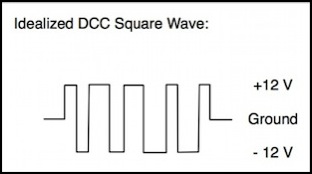
DCC isn’t a sine wave, it’s a square wave with variable-duration peaks. If you select address 0 (DC compatibility) and set the throttle to speed zero, you should get a square wave with symmetric peaks. You can use a purpose-built DCC voltage meter, such as the RRampMeter to measure this, although there are other methods. Frankly, I don’t think any serious DCC model railroader should be without an RRampMeter or equivalent; it’s one of my indispensable tools; I own two: one built into the power management panel of the layout, and one in my toolkit.
Because it’s easier to measure DC voltage, Digitrax provides instructions for calibrating their command stations using a DC voltmeter and measuring peak voltage. Basically, just measure each rail output in DC relative to the command station common ground, then add the two numbers. This is a fairly good method: since DCC is a square wave a DC meter will average the peak voltage of half the cycle with zero for the other half, yielding one-half peak. Adding the two gets you peak voltage, and compensates for any difference between the two. RMS for a pure square wave should equal peak voltage, and for DCC the two are “close enough” for most purposes. But it only works if your command station has a ground to measure against; most good ones do (this goes by several names, including “booster ground”, “common ground” and “home ground”). I’ll compare how well that works with an RMS meter and an RRampMeter below.
Note: the “ground” on a command station isn’t necessarily the same as the “earth ground” aka “safety ground” found in house wiring, although it is possible to connect booster ground to an earth ground (and useful, as this will discharge any static charge than might otherwise build up). If you don’t connect ground to earth, the booster ground will be a “floating ground”, which is still useful as a reference point between multiple boosters. Just make sure booster ground isn’t already connected to earth ground through the command station, as multiple ground paths create “ground loops”, which can be bad for electronics. And, if you have multiple boosters (or other layout devices using a ground, such as DCC circuit breakers) make sure they all connect to the same ground (e.g., wire all of the booster and circuit breaker grounds together).
Assuming you use the “booster common” wiring method (as opposed to “common rail”, see Layout Wiring for the difference) circuit breakers need to access the common ground, so this method will also work to measure the output of circuit breakers. But if those aren’t located close to the track, it won’t work for measuring track voltage (unless you extend the ground line to convenient access points).
Rather than measuring peak-to-ground, you can also measure peak to peak and divide by two. Most meters won’t do this, but an oscilloscope will and some meters will also.
However, those methods (peak to ground and peak-to-peak) have a problem: square waves are prone to distortion, which can increase the peak voltage without altering the power in the signal (i.e., RMS voltage remains unchanged). So this method works best close to the command station, where distortion should be minimized. As will be seen below, it also probably works best on an unloaded power supply (i.e, when no trains are running).
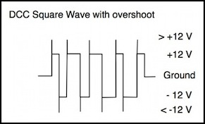
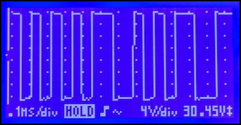
DCC In the real world - not quite square waves (oscilloscope shows output from a Zephyr command station)
When you look at the diagrams above, it might seem like this “12 Volt” system really has 24 volts, because the peak-to-peak difference is twice the peak-to-ground difference. But the important part is that at any given time the peak is about 12 Volts away from the ground, and this results in the voltage being averaged to 12 Volts. If you run a 12 volt square wave DCC signal through a rectifier (which is what a decoder does), you’ll get a constant 12 volts DC (minus the loss in the rectifier, which is typically around one volt) as the power supply. The rectifier is, in effect, averaging the voltage to get DC.
In decoders, the output of the rectifier is further varied by the decoder, to supply the motor with a variable average voltage from 0 to the output of the rectifier (possibly minus additional loss in the decoder circuitry that varies the output). Thus the maximum motor voltage will be less than the peak (i.e., RMS) voltage of the DCC signal.
Note: when I say “variable average voltage”, what I’m talking about is a technique called pulse-width modulation (PWM), which is a bit beyond the scope of this page, but it’s how most motor decoders provide a variable output to the motor using a full-voltage input from the track. See the Train Power Requirements page in the DC section or the Back-EMF page in the DCC Decoders section for additional discussion of PWM, as well as the PWM page for a more in-depth technical discussion.
Distributing Power
To get the power from the command station (or more correctly the power station typically incorporated in the command station) to the train, typically the rails are used. Some modelers use live overhead wire, called catenary, in addition to the rails to more closely replicate real-world electric trains. In a simple model railroad, connecting the command station to the track in one location is all that’s needed. As a railroad grows, additional connections and ultimately a “power bus” will be required.
The basic limitation of rail is that it’s not really a very good conductor. Even nickel-silver rail is essentially brass: a copper/zinc alloy (nickel-silver adds some nickel), and that doesn’t conduct electricity as well as pure copper wire. When the track is about twenty feet from the train to where the power pack connects, you can be losing a full volt of power with just one locomotive, and the loss increases with more (or with imperfect track connections, like sectional track). An excellent site discussing this topic is Allan Gartner’s Wiring for DCC site, and in particular the page on Track and Wire Resistance. See also my page on wire Ampacity.
If you want to run multiple trains, or have tens of feet of track, then you need to run a “power bus”, which is nothing more than a pair of heavy wires (14 gauge is typical) run below the track, with periodic “feeders” (small gauge, short wires) connecting the “right” bus wire (often red) to the “right” rail and the “left” bus wire (often black) to the “left” rail. Left and right are somewhat arbitrary; you just have to be consistent so that you don’t connect a “right” rail to a “left” rail anywhere (or if you do, as in a return loop, then you need a reversing circuit between the power bus and the track, which is a special kind of circuit breaker).
For some more basic information about wiring, see my DCC Layout Wiring page.
