Japanese Railway Signals and Signaling
A soon as railroads needed to run more than one train along a section of track, or had two tracks that intersected or crossed each other, there was a need to control the trains. In the earliest days, train operation along a track was controlled using a combination of timetables: lists of when a train was allowed to use a section of track, and written train orders handed out at stations along the route when needed. Signals, originally simply flags, movable boards, or balls that could be raised on a mast to make them visible, were developed to stop trains at crossings or at stations when train orders needed to be handed out. At night, oil lanterns were used.
Electrically-operated signals were developed in the late 1800’s, and in use before 1900 according to an 1897 article (see Railway Signal Association journal reference), although the poor visibility of the lights during the day led to a preference for electrically-operated semaphore (moving arm) signals either externally lit or equipped with lights, rather than lights alone.
At first signals were manual, but In the late 1800’s the first track relays were developed. These were systems capable of detecting a train on a section, or block, of track, and allowed certain signal functions to happen automatically, without human intervention.
Although railroads are slow to change working safety systems, and relays similar to those of 1900 still control many railroad lines around the world, and semaphore signals are still in use in a few places, the technology has evolved. For much of the twentieth century signal control was done by a complex system of electromagnetic relays, and these are still widely used for basic functions, although in many places they have been replaced with more modern systems. But with or without local relays at the signal, a modern signal is just one part of a more complex train control system incorporating computers and networking systems.
Although Japanese signaling practice was influenced by British practice, and later adopted elements from American companies, it has developed into a unique system. While it is tempting to draw parallels with other systems, and there are some similarities, it would be very misleading to do so in general.
Two of the basic principles behind Japanese practice are simplicity and short blocks. Short blocks allow trains to follow in close succession without encountering speed restrictions beyond those necessary due to braking distance. And since Japanese freight trains, when they occupy shared lines, are short and relatively light by comparison with those in other countries, maximum braking distances are relatively short. Train spacing on busy lines is often as short as a few minutes. Short blocks mean that a signal is taking into account conditions on several of the blocks ahead of the train, and this makes the information provided by Japanese signals more complex than that of most other railway signaling systems.
Note: the specific signal aspects used in Japan have moved to their own page:
Japanese Signal Aspects. This page now provides an overview of Japanese signals and their usage.
Purpose and Function of Signals
The purpose of a signal is to prevent train collisions while enabling efficient use of tracks. This is usually done by having a signal control access to some protected section of track. This may be a long stretch of single track (protected by a so-called “block signal”) or a junction of two or more tracks (called an “interlocking”, and protected by a signal called a “home” signal). When trains can run in both directions along a track or through an interlocking, an appropriate signal will be placed along each track providing access to the protected track. In the U.S., Federal law requires signal protection of every track leading to an interlocking, even if it is normally only used for outbound traffic, but this is not necessarily done elsewhere and Japanese practice likely does not require this.
Signals control motion in one direction, although a line may be signaled for bi-directional traffic, and if so will have signals facing in both directions (but a given signal only applies to one direction). Trains also, in general, are only allowed to operate in one direction without some kind of special authorization. Trains engaged in shunting (moving about within a controlled environment) are an exception to this, and are typically controlled by special shunting signals, but again each of those applies only to one direction of motion. Reversing a train can create a safety hazard, and may result in dismissal or retraining of the driver (see the MLIT accident report for the 2005 Fukuchiyama accident in the references for some discussion of this).
Signals may describe how a train is supposed to operate in terms of speed (e.g., a yellow indication meaning “do not exceed 28 mph/45 kph”), or warning of conditions ahead (a “restricting” aspect typically means “operate at 15mph/25 kph, prepared to stop short of obstruction”), or various combinations of these. When signals primarily describe speed, the system is said to be a “speed signaling” system. When they primarily describe impending direction changes, which can imply speed (e.g., “be prepared to take the diverging route at the next switch”) they are described as “route signaling”. Japan uses something of a hybrid system, with primary signal heads providing speed-based guidance, but additional signals or indicator lights providing information about routing.
Signals along tracks used at moderately high speed are typically located on masts beside the track, or overhead structures, so that they are easy to see from a distance. Signals in yards or stations, where trains operate at slow speeds and space is at a premium may be “dwarf” signals located low to the ground. Originally overhead signals were always placed on the Engineer’s (Driver’s) side of the train, but with modern cabs allowing visibility to both sides of the track, this restriction has been relaxed. It is still common to see signals to the right of the track on “right side running” systems (such as the U.S.) and on the left side of the track for “left side running” systems (such as Japan). For very high-speed use, or in very dense systems, wayside signals are replaced with cab signals, lights inside the operator’s cab of a train (cab signals can also be used as a supplement to wayside signals). On very lightly used track, signals may be omitted and replaced with one of the older forms of authority (e.g., a form read to the engineer by a remote authority over the radio, granting them access to a specific section of track for a specific duration).
Form of Signals
A typical Japanese signal is a color-light signal, meaning that it provides information using lights of multiple colors, with both color and relative position having meaning. This will have one head (one dark surround) with multiple lamps arranged in a vertical row. More than one lamp on the head may be lit, and lamps may be flashing. All of this serves to communicate a maximum allowed speed. Such a signal will normally be located at the driver’s eye level to the left of the track (the train driver’s side) or on an overhead structure directly above or slightly left of the track.
More than one signal head can share a mast, although there will be one main one, with others arranged at a slightly lower level and off to either (or both) sides. Where more than one head exist, the main head normally shows the condition of the principal route, and the others show the state of secondary routes reachable from the same track.
These Main signals may modified with a variety of other types of specialized signals (see next section) or signs. Among these may be route indicators, which eliminate the need to have more than one head on the mast by showing which of the possible routes the head is presently describing.
Position-light signals are also used in Japan, in some limited ways. In a position-light signal, all the lights are the same color (usually a yellowish white for high visibility) and it is strictly their relative position that matters. The usual convention, around the world, is that a vertical orientation means “clear”, a horizontal orientation means “stop”, and a diagonal orientation to the right means “caution”.
Shunting signals are usually small position-light signals with two lit lamps, which may stand alone or be placed on a mast with a non-shunting signal. If they share a mast, they will always be a significant distance below the larger signal.
Repeater signals will often use a circular head position-light signal with three lights lit simultaneously. See the
Signal Examples page for a couple of examples of repeater signals.
Signal Types
Signals in Japan divide into several broad types, which are covered in more detail on the
Signal Types page:
- Main Signals (
主信号機, shu shingōki): these include Home, Starting and Block signals
- Shunting Signals (
入換信号機, irekae shingōki): these allow for low-speed movements within a local area
- Subsidiary Signals (
従属信号機, jūzoku shingōki): these are tied to a main signal and provide advance notice of its indication
- Call-on Signals (
誘導信号機, yūdō shingōki): a signal used, mainly at stations, to permit a second train into an occupied block
- Signal Appendix (
信号付属機, shingō fuzokuki): this is not a signal, but an indicator attached to a signal that modifies it
Main signals control the operation of trains both within stations (or other junctions) and between them. Unlike some other railway signaling systems, Japan does not draw a distinction between block and non-block signals or the aspects they can display. These signals will consist of a single “head” (a dark surround with a vertical row of up to six lamps) on a tall mast or mounted to overhead structures, but this head may be supplemented with call-on and/or shunting signals, as well as signal appendices. Signs may also be appended, indicating the type of signal, the block number, or the track to which the signal applies. If multiple signal types share a mast, the main signal heads will always be above all other types.
A shunting signal authorizes a train or locomotive to move at moderate speeds (45 kph) within the bounds of a station (or similar environment) even when a Main signal is at “Stop” (red). A shunting signal may be either a color-light or position signal (the latter is typical on JR railway lines), capable of displaying Stop (R), Caution (Y) and Proceed (G), or Stop and Caution, or Stop and Proceed. A shunting signal is normally a low signal, but may be mounted on a mast with or without another signal (it will always be below any Main signal on the mast) or on overhead structures. Shunting signals are always interlocked to display “Stop” if the block ahead is occupied or has switch points set in a way that would prevent movement. They will also be interlocked with normal signals if both could permit a train into the same section of track, although “section of track” may have a slightly different meaning from that used by a larger signal. A shunting signal thus cannot authorize two trains to share a section of track.
Note for North American readers: A shunting signal is very different from a North American dwarf signal, despite the apparent similarities. Dwarf signals are essentially low-speed versions of Main signals in North American practice, and you either have one or the other at a given location. Japanese shunting signals follow the system more common in Europe, where they are a somewhat separate signaling system constructed in parallel, so that both types will exist and control access to the same section of track for different purposes. They are, however, interlocked with turnouts and operate based on information from track occupancy detectors, similarly to main signals.
The principal use of a call-on signal is to authorize a train to pass a Home signal protecting a station platform when that signal is at “Stop” (red) because another train is occupying the platform. This can be used when joining two trains together, or to allow two short trains to simultaneously use a long platform. A call-on signal is a single yellow light or two white lights on an upwards diagonal, with a separate surround, mounted below or below and offset to the right, from the signal it modifies, at a distance of at least 60 cm (about two feet). A call-on signal is the lowest signal on a mast, and will be below any main or shunting signals and any signal appendix.
Subsidiary signals are signals that provide advance notice of another signal. They come in three types:
- Distant Signals (
遠方信号機, enpō shingōki)
- Passing Signals (
通過信号機, tsūka shingōki)
- Repeating Signals (
中継信号機, chūkei shingōki)
A distant signal is identified by the surround being rectangular rather than oval. Both distant and passing signals take on an aspect separate from that of the signal that they provide advance warning for (e.g., showing Caution if the upcoming signal is at Stop), but the difference is that a distant signal can show a reduced-speed aspect in addition to simply Proceed (G) or Caution (Y). A repeating signal is a position light signal that shows the same indication as the signal it is linked to, and is used when visibility of the main signal is very poor. All three are typically used when curves or obstructions limits advance visibility of the main signal.
A signal appendix is typically some means of indicating the route to which the signal applies. These may use lights, arrows, or alphanumeric displays, and may apply immediately or give advance notice, depending on the type of appendix used. While a route appendix is normally applied to a Main Signal, it can also be applied to Shunting or Call-on Signals.
Signal lamp lenses for home, start and block signals must be a minimum of 100 mm and be spaced by a minimum of 200 mm (180 mm in tunnels). All spacings represent center-to-center distance of the lenses, regardless of lens diameter. Other signals must be a minimum of 90 mm in diameter and be at least 600 mm from a home, start or block lens (passing signal lamps must be a minimum of 800 mm below the lowest home signal lamp). Call-on signal lights must be a minimum of 250 mm from shunting signals if both exist. Finally, lights used in position-light signals (this includes shunting signals) must be at least 250 mm apart, 150 mm in tunnels.
Signal Aspect and Indication
With Main, Shunting and Subsidiary signals, the meaning (“indication”) of the signal is provided by color lights (called the “aspect” of the signal). Repeating and Shunting signals may also provide an indication using lights positioned relative to each other, mimicking the form of a semaphore signal blade that can be vertical (Proceed), Horizontal (Stop) of upward diagonal (Caution). For more on this, see the
Japanese Signal Aspects page.
Note: the term “aspect” is sometimes used less precisely to include the indication, but in formal definition “aspect” only means the colors and arrangements, and not what they mean.
Signals, Control, and Related Systems
The signal is merely the visible portion of a large and complex multi-layered system for controlling the motion of trains. There are several portions to the whole: the wayside equipment (signals, etc), the system that enforces trains operate in accordance with signals (automatic train stop and similar systems), local control of wayside signals (interlocking systems), and wide-area traffic management (dispatching, Centralized Train Control, and a number of complex control systems). This is a “layered” system so, for example, older relay-based interlockings can continue to be used even with the most modern centralized control systems.
Interlocking is the name given to the way signals and turnouts (track switches) are connected to each other such that one cannot be changed if any of the others are in a state that would make the change result in an unsafe signal indication or a change in the track conflicting with existing signal indications. Interlocking has undergone a number of technological changes since it was first introduced. Japan’s first interlocking system was installed at Shinagawa Station in 1887, and was mechanical. Modern interlocking systems are computer-based (although earlier relay-based systems remain in use).
Japanese wayside systems have additional capabilities not often found in other nation’s railways, such as detectors that can identify if a car or pedestrian is between crossing gates when they come down, or has fallen onto the tracks from a platform. Japanese stations and grade crossing also often have manual alarm buttons that can be pressed by someone on the scene to report a problem, a feature that would be unlikely to work in most other nations.
Signals and other wayside devices (crossing gates, block occupancy detectors, etc) work together autonomously to provide a fail-safe method to prevent two vehicles from occupying the same space, or otherwise avoiding an accident by stopping a train from entering a section of track (known as a “block” of track). Although humans can provide inputs, such as pushing an alarm button if someone falls from a platform onto the tracks, automated systems, such as photocells to detect when someone has fallen onto the tracks, are used as much as possible.
Signal Technology
Signals have been a part of railroading since the earliest days, although early ones were mechanical or involved oil lanterns. But the “modern” electric signal uses a simple technology based on relays that has not substantially changed since the “track circuit” was invented in 1883: a voltage is applied across the rails in a section of track, and the presence of a train causes a short-circuit between the rails, which trips a mechanical relay, sending an electrical signal down a wire that can be used (through more relays, or more complex controls) to control signals displayed to other trains.
Signal systems are called “vital” systems (and their relays “vital relays”). What this refers to is that they are (and usually must be by law) constructed such that any failure will cause the system to go into its most restrictive condition. Normally this means that in any failure, signals will turn red, or go out entirely (a dark signal is typically interpreted equivalent to a red one).
Signal changes can also be triggered through other systems than just track circuits, including detectors for obstructions on the track, such as fallen rock or flooding, by central control by a train dispatcher, or by local warning systems. Many stations have detectors for obstructions on tracks that can detect when a person has fallen off the platform and stop approaching trains, and Japanese grade crossings have alarm buttons allowing trains to be warned of hazardous conditions directly (a system that would not work in most Western nations).
Although a human authority may have a degree of control over a signal, being able to direct them to show “Stop” or a non-“Stop” aspect, they generally cannot directly control what aspect is displayed. That is under local control by the vital relays, taking into account permanent track restrictions and local conditions (e.g., the settings of related switches and signals). Signals such as “call on” signals (discussed below) are an exception to this rule.
The development of microelectronics and new telecommunications technologies such as fiber optics, cellular and satellite radio, and packet networking is slowly being applied to railway signaling. Since signals are so critical to the safety of both people and equipment, this is an area where innovation moves slowly. Among the recently introduced technologies are precise locating of trains via GPS and two-way radio communications with centralized dispatching systems. This supplements track circuit detection systems, and provides more detailed information, while keeping the track circuit as a fail-safe. More recently, systems have been developed that allow a train that has been in an accident (and thus is potentially blocking adjacent track) to report this to the signaling system even if the crew is incapacitated, to avoid a secondary accident. Neither of these developments is in use yet, as far as I have been able to determine.
Another interesting development allows the use of remote terminals by maintenance supervisors to ensure that tracks they are working on have been removed from use (in the past this would have been done verbally, via radio or phone with a dispatcher, and mistakes could be made).
The latest innovation, under development by JR East as of 2008, is a “distributed” signal system, where some of the control logic (likely the “vital logic” formerly found in a nearby equipment cabinet) is installed on the signal itself, and a fiber-optic packet network (UDP over E-PON if you care) is used to communicate between central control systems and the signals. This approach simplifies wiring, reducing possible failures, at the expense of adding risks based on software or processor failure. However, such risks can be managed, and the promise is a more flexible and reliable system, likely at a lower overall cost.
But at the core, even new technologies do not fundamentally change the three components of signaling: detection systems, central control, and the use of lineside or cab signals to display information to the train operator.
Block Signals and Automatic Block Control
Automatic Block Signaling (ABS) is a type of signaling system where a signal is controlled by track conditions on the far side of the signal from the perspective of someone viewing it. In particular, if a train occupies the block, the signal will be set to prevent other trains from entering the block. ABS also uses information about the physical layout of track and the positions of track switches to prevent a signal from allowing motion when some condition exists that would allow for a conflicting train movement, even if there isn’t a train in the way currently.
Japanese ABS used on single-track lines requires that start signals at opposite ends of the line are interlocked. Thus technically it is an Absolute Permissive Block type of ABS, although the term ABS is used in English translations to describe it.
Japanese ABS also includes a type called “semi-automatic block” which appears to be used for single-track lines. This uses entry/exit detection rather than track circuits, so in effect it “remembers” that a train has entered but not left a block. This is probably used to avoid unnecessary replication of track circuit systems on very long but lightly-used lines. Aside from the type of detection used, it appears to be functionally equivalent to ordinary ABS.
When blocks are smaller, or trains run faster, there may be need of additional signal aspects used to slow the train down before it reaches the “stop” signal. Speed restrictions may also be signaled via lower-speed aspects, due to the track design and the route selected. For example, a diverging route through a switch will typically limit the speed a train may safely use to around 50 kph unless a special high-speed switch is used.
Interlockings and Specialized Signals
But autonomous protection is only part of the whole. External control needs to be provided at stations and over whole lines. Where signals operate in conjunction with switches or tracks crossing other tracks (most typically in Japan this is at stations), control over the switches needs to be “interlocked” and tied to the signaling system, so that conflicting movements cannot be authorized. As in other countries, in Japan this was originally done manually by local operators pulling levers, later remotely via Centralized Train Control (CTC), and finally a degree of local autonomy was returned through complex computerized systems.
In stations and yards there are “call-on” signals and “shunting” signals, presumably under local control. Call-on signals tell the train operator that they may pass a signal set at “stop” at Restricted speed (25 kph) while being on the alert for other trains. One typical use of these is to allow a second train to enter a station when another has already passed the home, or “entry”, signal for that station track, permitting two trains to occupy a long platform.
Shunting signals provide a similar function. However, unlike call-on signals that provide a simple “yes” indication, shunting signals can provide more complex indications (Stop, Proceed and Caution) and may allow speeds up to 45 kph (depending on circumstances). Shunting signals are signals rather than simple indicators. Shunting signals may themselves be equipped with call-on indicators.
An important difference of Japanese practice to U.S. practice is that in the U.S., an interlocking is usually treated as part of the next block beyond it for outward movement, while in Japan it is common to treat it as independent of that block. Thus in the U.S., signals control entry to an interlocking but also implicitly allow exit from it, while in Japan it is typical to have either a starting signal to control departure into the next block, or for a block signal to be located at the exit from the interlocking (or both).
Central and non-so Central Control of Trains
As railroads around the world grew more complex, the need for some kind of coordination of train movements across a wider region became obvious. At first trains had operated simply according to planned schedules, but this approach could not provide the adaptability that a large and busy system required. The telegraph allowed formerly-independent stations to work together, and over time this gradually became more complex, until centralized dispatching started to take over from decentralized and autonomous local control. Initially dispatching was simply a central authority, directing local operators as to which trains had priority via telegraph or other systems.
An important step was the conversion from mechanical to electrical control of switches and signals, begun in the late 1800’s and culminating in the development of Centralized Traffic Control (CTC) in 1927, which gave a single operator, or dispatcher, the ability to directly control systems beyond their line-of-sight while still enforcing safety rules through “interlocking” systems that limited the changes that could be made. Other systems were developed prior to CTC for cooperative or automatic control over a wider set of systems, and some of these, in particular Automatic Block Signals (ABS), continue in use.
ABS allows signals to operate without an operator, sensing train location and switch positions and sending information about them to each other so that correct signal aspects can be displayed to prevent two trains from entering a block (a length of continuous track with only two endpoints) at the same time. This is primarily of use on long lines divided into many blocks with nothing more complicated than sidings for passing trains or local industry. An ABS system may be bi-directional, and if so there is often some method to lock the direction so that trains can follow other trains without an opposing train being permitted into a section. The common form of this is known as Absolute Permissive Block control (APB), and both original ABS and the APB form remain in use around the world.
In effect, both ABS/APB and CTC provide for a layer of control above the wayside systems. Earlier mechanical and early electric systems had provided the interlocking function under local control, with ABS coming into use between locations with more complex control requirements (i.e., junctions and terminals). CTC kept all of that, while introducing the concept of a remote dispatcher providing an overall control function. CTC does still permit a limited degree of local control, such as train crews manually operating switches that are interlocked (locally) and monitored by the larger system. But CTC also allows the central dispatcher to plan a route through a set of switches, and set it (for a limited duration or until cleared by events) so that a train could move over a larger area without becoming blocked by an opposing movement.
The use of CTC mostly eliminated the need for local control, and over time as systems were updated local operating sites (“towers” or “switch boxes”) were eliminated in favor of direct (but interlocked) remote control over wayside systems by the dispatcher. However the problem with this approach is that a single dispatcher can only manage a certain number of things at a time, and in a complex situation there is an advantage to local decisions being made autonomously. In some places, particularly in Japan’s busiest stations, local control remained delegated (or was returned) to local officials such as a station master or yard master. One illustration (see Signaling Systems paper in references) shows a two tier system with CTC consoles at both local stations and a central traffic control center.
CTC in Japan
With the rise of more complex electronics, in particular computers, CTC began to be augmented with control systems that could handle some of the basic route planning and control functions, reducing the load on dispatchers (and thus allowing them to less directly control more trains or a larger territory while still leaving the details to local control).
Japan began adopting Centralized Traffic Control (CTC) in 1937, and computerized control layered atop it (under the name Program Route Control or PRC) with the construction of the first Shinkansen line in 1964. Collectively the two are known as the “Traffic control system” or “Traffic Route Control”). However when JR East was formed in 1987, signaling in the region around Tōkyō was still largely a distributed manual system with automatic blocks between stations and individual stations entirely under local control. Local computerized control of interlockings (mainly tracks around stations) was introduced in 1985 (at least in what was later JR East territory).
This doesn’t mean that there was not also a central authority function (i.e., a dispatcher or equivalent), but that it was operating in more of a coordination role than directly controlling operations. This was partly due to the scale and complexity of operations in the metropolitan region, and the infeasibility of one dispatcher managing even a single line.
In 1996 JR East introduced the Autonomous decentralized Transport Operation control System (or ATOS). This was first introduced on the Chūō line, and later extended to many other lines (18 lines as of 2012). This allows stations to perform autonomous local control while still being part of a larger computerized control system that is aware of train schedules and other factors affecting the prioritization of activities. This was essentially a layer above the dispatching systems (CTC with PRC, or the Traffic control system), and it allowed extending more direct central control to lines or regions with more complex operations. ATOS still works through CTC, although a modern computer-driven version of CTC. ATOS did not, however, extend to more complex planning.
Separate from dispatching (authorizing individual train movements) is the scheduling and planning of train movements, and the adjustment of these to deal with problems on the line (e.g., accidents blocking one section, failures of electrical or signaling systems, etc). Until recently this has been a highly-manual activity, with train schedules planned in advance and adjusted in emergencies by specialists. An electronic but non-computerized version was first developed for Shinkansen and in 1995 a computerized replacement system, Computerized Safety, Maintenance and Operation Systems of Shinkansen or COSMOS, was adopted.
You can think of this as a three-layer system: at the base are the wayside systems themselves, signals and turnouts, as well as track relays to detect trains. This is the visible portion. Above this is the route control system, which includes the vital relays (or modern equivalents) that prevent illegal configurations of wayside systems, as well as their interfaces to the CTC systems. Also at this layer are the train control systems (ATS, ATC, etc) that enforce signals (described below), and control inputs from “route request” systems. This layer is all located “in the field”. Finally there are the centralized systems (the “traffic control system”) consisting of PRC and the centralized portion of CTC, as well as ATOS and COSMOS.
So signals and turnouts (track switches) are just the visible portion of a very complex system, with some parts still acting much as they did more than a century ago, and others using much more complex and modern capabilities. The purpose of the system has not changed: it remains the efficient and safe movement of trains. But how this is done today is in some ways completely different from how it was done a century ago, and in others nearly identical.
Note that as in other countries, CTC and all these other elaborations are only used on lines where conditions require this degree of coordination and control. A simple line with a few stations or relatively light use could operate on a more basic system, such as APB, or entirely without signaling under some other form of authority.
Signal Enforcement
The most common cause of accidents on lines with signals is human error, often due to misreading or overlooking signals or speed limits. The problem is compounded with short blocks carrying frequent trains and even worse with high-speed trains, where there is little time to react to changing signal indications. Over the years a number of systems have been put in place to address this problem by enforcing that trains operate in accordance with signals, even when the human operating the train fails to react.
The first of these was Automatic Train Stop (ATS). This system was installed on “all Japanese National Railway tracks” by 1966. A more sophisticated variant was created later (ATS-P) but both serve the same function: to stop a train that is failing to operate in accordance with the indications of signals. ATS systems work only when passing signals, using coils between the tracks to transmit the signal indication to the train. An elaboration of this is Automatic Train Control (ATC), introduced with the first Shinkansen line in 1964, which is a continuously-operating system, allowing trains to be braked to match speed limits and to stop in advance of red signals.
Another enhancement was to make this digital, allowing more sophisticated control over train speed via “braking curves” that allow trains to operate at the maximum possible speed while still braking gently enough for routine passenger use. Japan’s first Digital ATC (D-ATC) system was introduced in 2003 on the Keihin Tohoku line, and a variant for Shinkansen (Digital Shinkansen ATC, or DS-ATC) on a new section of the Tohoku Shinkansen line in 2002.
The most recent elaboration eliminates the need for most of the wayside systems (ATC effectively eliminated the need for signals, although they often still exist). The ATACS system uses cab signaling and radio communications between trains that know their own location through GPS to avoid having trains operate in a manner that would cause two of them to collide. This eliminates block occupancy detectors (although it still needs to tie into local alarm systems and crossing gates). This was trialed in 1995, but does not yet appear to have been put into general use. Proposals for Positive Train Control (PTC) in the U.S. are similar to this approach. One problem with eliminating block occupancy detectors is that this prevents the detection of broken rail or non-equipped trains or other equipment on the line (e.g., a freight car that detached from its train or rolled out of a siding).
Signal Structure
Signals consist of one or more “heads” (sets of lights), and can be mounted on a pole (called a “mast”) or attached to overhead structures. Typically with multiple tracks, there will be one head for each track, either mounted above and to the left (where left-side running is practiced) of the track, or on the outside if there are two close parallel tracks. Japanese practice sometimes uses multiple heads for the same track, with each denoting conditions on one track that can be reached from the current track, with the head for the straight-ahead route (called the “through” route) slightly above the level of the others.
In such cases, the other signals are apparently a type of Preliminary Route Indicator, and as such are subordinate to the next Home, Starting, Block, Distant or Repeating signal. It would appear that the aspect displayed is identical to that on the signal it is subordinate to, but that’s not completely clear to me.
Another form of Preliminary Route Indicator is simply a marker of some sort that shows that the signal is displaying information for a specific diverging route rather than for the normal through route. In such cases the indicator may be a simple white light, an arrow, or a digital number sign providing a track number. The latter may be Route Indicators (see below) rather than Preliminary Route Indicators.
Per the MLIT document, a “route indicator” (different from the preliminary route indicator) is a modifier applied to a home or starting signal head (rather than a signal in advance of one) that can indicate information for more than one route. Wikipedia describes this as a shinro hyōjiki (進路表示機, lit course display machine) one type of signal appendix or shingō fuzokuki (信号付属機, lit signal adjunct).
A signal head may be mounted atop the mast, or on an arm offset from it either in front or to one side. A mast will usually have a ladder on the back side of the mast, and a platform in front of the head, where someone can stand to replace bulbs or clear snow from the lens. In some cases, ladders can be to the side, and access platforms on the rear or side, but most examples I have seen of Japanese signals have the ladder to the rear and the platform in front. Masts will usually bear an identifying number on a plate (or on the signal head itself) which can be read by the engineer of a train, and may have other markings to designate the type of signal.
Signal heads may also be mounted to some other structure, including station platforms and supports for overhead electrical catenary, although there will often be a short pole to which the head and any associated number or marker plates or lights is connected that is attached to the supporting structure.
Signals typically occur in sets, with separate signals for each direction (sometimes only one direction has signals), often on opposite sides of a track switch or switches they are protecting (an “interlocking”). There will be one or more electrical cabinets located nearby these signals, where the relays that control them are housed. There is often an electrical junction box built into the base of the mast, but in some cases the wiring will all be handled within the larger cabinet.
Note that many lines in Japan use double track with each track signaled in only one direction. There is some double-track signaled for bi-directional use (and, of course, single-track lines are bi-directionally signaled if they are signaled), but on the majority of lines signals will not be located back to back, and while signals for the two directions may be located in close proximity (to simplify electrical wiring or because of external factors), they don’t have to be.
The head itself is typically colored black, to help the signals colors stand out in daylight, and the mast, ladders, and platform and electrical boxes will be a silver metal color (in some cases concrete masts are used, which are unpainted). In some cases, the mast is painted white.
Shunting Signals
Not discussed above are signals used for low-speed operation (in yards or near stations) that typically display only stop or caution aspects, and which are interlocked with both track occupancy detectors and any track switches which may be set against the approaching train (i.e., they will display “stop” if there is a train ahead or the current train is above to hit a switch set against it, and clear otherwise). These are typically small position-light signals using white lamps (some also use colored lamps with a specific arrangement).
Wayside Signals
Wayside signals are related to shunting signals in that they control non-mainline activities including shunting. However they take the form of two-light and three-light tall signals masts with rounded surrounds, similar in appearance to ordinary block, home and entry signals. A clear indication on a wayside signal is limited to 45 kph, making it effectively identical to a caution.
Wayside signals are also used with Shinkansen to control entry and exit to “a station and halt” when cab signals are inoperative.
Unknown Type
Small green dwarf signals are placed near switches on signaled lines (including the cab-signal-only Yamanote line). These appear to be used even if the switch is part of a signal-protected interlocking. It s likely that these provide a visual indication that the switch is set to a through route, allowing more distant confirmation of that than waiting until the points can be see. As such they would be a check on the signaling system rather than a part of that system.
This is probably a “point indicator” as defined in the MLIT document; approved model specification, X-26, article 119, (2, indicators), [7]: “points that need to indicate route-clear directions shall be equipped with a point indicator”.
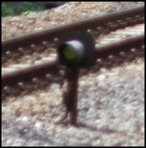
Green Dwarf Signal (at crossover on Yamanote Freight Line in Harajuku station)
Photographer: Onnie Koski
References
For examples of typical signal masts and lights, see the Example Signals page.
Sources and other links of Interest:
Centralized Traffic Control, GRS Bulletin 169, March 1938
This bulletin provides an executive-level overview of CTC, by the General Railway Signal co., which invented the technology. Japan adopted CTC in 1936, so this document may reflect the initial systems used.
Centralized Traffic Control, GRS Bulletin 154, by Sedgwick N. Wight, August 1927
This bulletin is a discussion of the use of the original CTC system by its creator. Note that this version of the system is significantly different from later versions.
Defending Railways Against Nature, photostory (PDF), in Japan Railway and Transport Review #18, September 1998, shows a variety of detection systems used to report problems along the track to central control systems and dispatchers.
The Current Status of Signal Control Systems and Research and Development (PDF), Yoshinori Kon, JR East Technical Review #3.
This document includes, among other things, the 1936 date for the first Japanese CTC system, credited to the Tenri Line of Osaka Denki Tetsudo Co. Ltd. (now Kinki Nippon Railway Co. Ltd.). It also provides the 1964 date for the introduction of Program Route Control on the Tokaido Shinkansen.
Japanese Railway Signaling, has a number of photographs of example signals.
Journal of the Railway Signal Association, Volume 2 (Google Books)
Contains an 1897 article by V. K. Spicer, an agent of Union Switch and Signal, in which he stated that “The experimental stage has long since been passed and to-day automatic signaling is as much an assured success as the automatic air brake.” before going on to extoll the virtues of the electric semaphore. The journal also includes subsequent discussion showing that electric relay signals were in use, but still contentious (in part because they were located where there wasn’t a station agent to catch engineers who chose to disregard the signal).
A New Signalling System for Automatic Block Signal Between Stations Controlling through an IP Network (PDF), by R. Ishima, Y. Fukuta, M. Matsumoto, N. Shimizu, H. Soutome, and M. Mori, East Japan Railway Company, Daido Signal Co. Ltd., Hitachi, Ltd., Toshiba Corp.
Notes on Pennsylvania Railroad Operation and Signaling is an interesting history of some of the earliest U.S. signal systems (which build on British work). The Pennsylvania Railroad was a technology leader among the railroads of the late 19th and early 20th centuries.
A Railway Signal Control System by Optical LAN and Design Simplification (PDF), by Takashi Kunifuji, Jun Nishiyama, Hiroyuki Sugahara, Tetsuya Okada, Yamato Fukuta, and Masayuki Matsumoto, Journal of Networks, vol. 3, #7, July 2008.
Railway Signal (Wikipedia)
Railway Signalling (Wikipedia)
Railway Signals in Japan, Wikimedia Commons collection of photographs of signals.
Railway Technology in Japan - Challenges and Strategies (PDF), Hiroumi Soejima, Japan Railway and Transport Review #36, September, 2003.
This fairly high-level overview is notable as the source for the 1954 date of the first Japanese CTC system, citing Railway Statistics as the source, the the Keihin Electric Express Railway as the first CTC line.
Safety Measure of East Japan Railway Company (PDF), paper presented at the International Rail Safety Conference 2004, by Koichi Kawano and Kimio Sano, describes track maintenance safety measures, including use of remote terminals.
Signalling Systems for Safe Railway Transport (PDF), by Tetsuo Takashige, in
Japan Railway and Transport Review #21, September 1999.
Signals are Key, a blog entry comparing Japanese Railway design and its relationship to signaling with that of the Dutch railway.
Summaries of Major Railway Accident and Incident Reports, MLIT web page. While not directly discussing signal design, some accident reports do describe signal systems and how they fail in practice.
Technical Standard for Japanese Railway (English-language PDF), Railway Bureau, Ministry of Land, Infrastructure, Transport and Tourism. A collection of summarized ordinances and standards. See chapters 7 (Operation Safety Facilities) and 10 (Train Operation). Note: this is a 15MB document.
Toward Innovation of Signal Systems (PDF), by Masayuki Matsumoto, JR East Technical Review #7 (date uncertain but apparently 2012).
Additional information was taken from machine-translated Japanese web pages, including:
Japanese Wikipedia version of the Japanese Railway Signals page, which has more information than the English version linked in the text above.
Tarumi Technical center - explanation of “Main signal” types
Tenkyoku.com - detailed citations of operating rules for fixed signals at tenkyoku.com/drivinglaw/07-mainsignal.html and other pages, but the site requests that links point only to the main page.
Japanese-Language Wikipedia:
Japan Railway Signal (日本の鉄道信号)
Books:
These are about North American signaling (mostly), but provide some good detailed descriptions of the technology involved if you want to understand signaling at that level.
Elements of Railway Signaling, GRS Handbook 50, General Railway Signal co., 1954, hardcover (several hundred pages numbered by chapter, not sequential).
A 75th anniversary commemorative edition was also published in 1978, and both are available on the used market, but I’ve only seen the original. This has an immense amount of detail on all aspects of signaling (as of 1954), including very detailed descriptions of the design and functioning of relay systems, and just about any topic related to signals.
Introduction to North American Railway Signaling, by the Institution of Railway Signal Engineers (various authors per chapter), softcover, Simmons-Boardman Books pub., 2008, 210 pages, ISBN: 0-911382-55-0
This is a fairly technical book with lots of detail on how relays really work, in addition to some good discussion of signaling as it’s used, and a number of photos and diagrams (all black & white). While generally specific to North American practice, much of the contents are relevant to other systems.
Railway Operation and Control, by Joern Pachl, 276 pages, ISBN: 978-0-9719915-6-9, softcover, VTD Rail Publishing
This is a very detailed book with a good international coverage of signaling (among other topics), although it is oriented around North American and European systems and doesn’t cover Japan.
Railroad Signaling, by Brian Solomon, hardcover, 168 pages, ISBN: 978-0760313602, or paperback, ISBN: 978-0760338810.
Probably the most readable discussion of the topic, and with lots of good photos. It mainly covers U.S. signals (with some others used for examples of specific technology), but is a good introduction to general concepts.


