


Back EMF and Other Speed Compensation
In order to adapt the power produced by a DC motor to changing loads (e.g., when traveling up a hill), the motor controller needs to detect that the speed of the motor is slowing, and increase power to it. Conversely, when load is reduced (e.g., going downhill) power needs to be reduced. In a normal DC train, the “controller” is the human at the throttle. With DCC, there’s the option for the DCC Decoder’s motor control system to handle this automatically.
The Back EMF-based control feature in a decoder, which I’m going to abbreviate to just “BEMF” for simplicity, is a motor-speed control feature that uses Back EMF to determine the speed of the motor, so it can decide if it needs to change the supply voltage in response in order to return the motor to the desired speed. To be technical, it’s implementing a negative-feedback control loop to manage motor speed, with Back EMF as the feedback part. In a sense it’s acting like the governor on an old-time steam engine (which limited steam pressure into the driving cylinder when the speed of the engine got too high). The core of this is a software algorithm in the decoder that makes decisions about when and how to react to changes in the perceived behavior of the motor.
Back-EMF is most important with slow speed operation, to prevent a train from stalling due to a sudden increase in load (e.g., due to a track irregularity such as a joint or switch frog). Back-EMF is also useful for maintaining speed on a grade, although some people like to disable this for supposedly more-prototypical behavior (real trains slow down on grades). Finally, BEMF is useful when attempting to get trains to operate at a specific speed (e.g., in automated systems), since the speed will vary less due to other factors (grades, number and weight of cars, track condition).
Model trains can slow down for all sorts of reasons, and on a grade they will slow down much faster than a prototypical train would. You can, as some do, view that as “realistic” behavior, since distance on model railroads is selectively compressed, and real trains (big ones anyway) will slow down a lot on a long grade. Others like BEMF because it reduces or eliminates this behavior, allowing them to choose the speed.
Still others see BEMF as a way to compensate for the poor low-speed performance of a DC motor driven by a PWM signal (more on PWM below), particularly with high-frequency PWM.
Since I’m modeling short passenger trains rather than long North American freight, I don’t really see drastic grade-based speed changes as being realistic, and I see BEMF as a means to make the throttle a more direct control of the train’s behavior regardless of environmental factors, which is what I want. The same could also apply to someone running short switch-job freights, as they’re not going to behave the same on a hill as a mile-long coal drag.
This page describes what BEMF is, how decoders use it, and how to adjust decoders to make the best use of BEMF and related features. And, unfortunately, there aren’t any “one size fits all” answers to that last part. A decoder that works well for one locomotive on one layout, might not work as well under other conditions or in other locomotives, and tuning turns out to be very limited (and rather hard to do when possible).
The short advice is probably to turn it on with the manufacturer’s defaults, and if it doesn’t work then try turning it off, or adjusting what can be adjusted in line with the manufacturers instructions. And if all else fails, using a different manufacturer’s decoder. But trying to tune for optimal behavior is probably not going to produce consistently optimal results across all conditions anyway, and thus isn’t likely to be worth the effort if it’s already working.
But, as I’ll come to below, there are significant advantages to BEMF, and you need to do a few things to best take advantage of it. It’s certainly worth exploring, and after my explorations I’m convinced that it’s necessary, not just desirable.
Issues to Think About
It’s important to keep in mind that BEMF doesn’t provide an absolute speed control. A decoder has no idea how fast a train is moving, or even how quickly the motor is turning. What BEMF does is assume that if you set the train to run at speed “X” (meaning really that you’ve set the motor to a voltage that makes the train go that fast) with a given throttle setting under specific circumstances (such as on level track pulling 20 cars), then it’s going to try to maintain that speed going up or down hills, or if wheels going through a switch bind slightly, or if there’s extra drag when going around a curve. It’s also going to try to maintain the same speed if the load changes (e.g., when pulling 10 cars, or 30). However, this is ultimately limited by the motor: if it can’t pull 30 cars up a hill at speed “X”, no amount of adjustment, based on BEMF or anything else, is going to change that. Also, because it’s working on a voltage-based method, something that changes the track voltage (like a long section of dirty track, or another layout with a different command station) will change how the train runs at a given throttle setting.
And there’s a second caveat that comes from the fact that it’s increasing motor voltage to compensate for load: your top speed loaded is going to be less than the maximum possible top speed, since it needs to have that margin for increases. With most trains, that’s not a problem, as they tend to run at a couple of hundred scale miles an hour at full voltage, so you probably want some kind of speed table limiting the top speed anyway. On the other hand, if you model Japanese bullet trains or European high-speed-rail, with speeds of 200 mph (320 kph) or more, PWM may be more trouble than it’s worth. But even there, it may be helpful despite the need to limit top speed.
Depending on the manufacturer of the decoder, there may be ways to “tune” the behavior of this feature, to disable it via a function key, or to have it automatically disabled at higher speeds or when consisted. Tuning is important because the control system’s behavior depends in part on the characteristics of the motor and drive-train, which vary from one model to another.
Back EMF, because it responds to forces acting on the train, can be problematic when there are two independently-controlled motors in the train (e.g., when consisted, or for an EMU/DMU model with separate motors in different cars). The two control systems can end up acting against each other, causing jerky behavior. To some extent this can be mitigated by careful adjustments of the control system (e.g., settings in CVs used to “tune” it). Digitrax allows the amount of BEMF applied in a consist to be configured separately from that of a non-consisted locomotive, and this can be used to apply less BEMF to consists, which helps avoid the problem also.
Back-EMF will behave badly with dirty track or other causes of intermittent power pick-up since these create variations in load. BEMF is not a substitute for clean track, and may in fact require more attention be paid to cleaning to avoid problems, although it will help to an extent with problem spots that have poor contact, as long as they are relatively small.
DCC decoders often have other means of speed control designed to apply under specific circumstances, particularly with low-speed starts. These vary by manufacturer, and in some cases only apply if BEMF is not enabled (or is manually turned off).
I ran across an interesting comment recently. I have no clue as to its validity since I don’t have the equipment discussed. But the gist of it was that BEMF decoders are designed for motors that have armatures, and that they generally didn’t work well with coreless motors (typical of some European manufacturers, although Kato’s Unitram is also reputed to use them). The tip was to turn off BEMF with this and use something like TCSs dither instead.
DC Motors
Most model trains use fixed-magnet brushed DC motors. These include a central shaft (the rotor) with wires that turns inside a frame (the stator) to which is mounted a permanent magnet, as shown in the diagram below. On the rotor is mounted an iron armature, around which wires are wound to create an odd number of poles. Power is applied to a subset of poles via the commutator and brushes, creating a magnetic field in the armature.
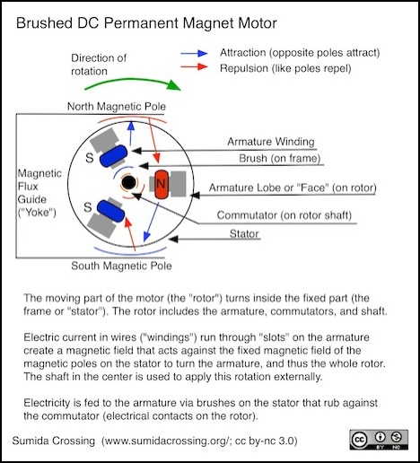
DC Permanent-Magnet Motor Design
In a motor, voltage (also called “electromotive force”) creates a magnetic field that applies a force against another magnetic field (created by the fixed magnets), and this force causes the rotor to turn. A characteristic of motors is that they are also generators: if you turn the rotor, the fixed magnetic field applies a force that induces an electric current in the windings. And this occurs even when the motor is turning as a result of a voltage applied to it. This “counter electromotive force” (also called a back electromotive force) effectively reduces the current required to turn the motor.
BEMF is proportional to speed, so at higher speeds less current is effectively used by the motor. This is why a stalled motor uses the maximum current (e.g., the “stall current” used to size a DCC decoder), since there is no BEMF-induced current. When a load is placed on a spinning motor (or the load is increased), it slows down, because some of the external force is no longer being applied to the friction within the motor, but taken away to be used. When the speed is reduced, the BEMF current is reduced, which causes the effective current drawn by the motor to increase.
A BEMF-equipped decoder senses the change in speed, and raises the voltage to compensate, applying more EMF to return the motor to its former speed. The typical method used to do this (for an DC motor without a separate speed-monitor) is to stop applying power to the motor for a brief time, and measure the voltage being produced by the motor-as-generator.
PWM
In a DCC system, the voltage supplied to the decoder is at a fixed voltage (around 12-16 volts). To drive the motor at different speeds, this must be converted to a variable voltage, or rather a variable average voltage (said another way, a variable power). The best way to do this in the compact space of a decoder is to use pulse-width modulation (PWM). With PWM, full-voltage pulses of varying duration are created: more/longer pulses create a higher average voltage, and thus a higher speed in the motor. While other methods exist, these are less efficient than PWM, and often have other drawbacks. Most if not all DCC decoders use PWM to drive the motor.
To be strictly technical, what PWM provides is a way to vary the average power to the motor, not the voltage (although if you average the on and off periods you can think of it as an average voltage). It does this by varying the percentage of time that the PWM output is high (at track voltage) relative to the period it’s low (at zero volts). This relative interval is known as the “duty cycle” of the PWM controller. A 50% duty cycle should probably cause the motor to turn at about half its maximum speed for a given track voltage (and note that this maximum will be different for a track voltage of 12 volts than for one of 15 volts).
A decoder’s PWM output is not continuous, but rather is a number of discrete “on” maximum-voltage output levels followed by “off” intervals (i.e., discrete duty cycles), with the duration of the shortest part depending on the base PWM frequency and the number of “levels”, which in turn is based on the number of bits used internally by the PWM controller (typically a functional block incorporated in a microcontroller chip). You need at least seven bits (128 levels) to fully reflect the level of control provided by a DCC throttle (126 steps plus zero). Any more isn’t necessary, but may be useful when Back-EMF is used, particularly at lower speeds. And some microcontrollers support up to 10 bits (1024 steps). However, this may be limited in practice by the frequency of the circuit driving the motor controller, for complex reasons related to the accuracy and granularity of timing needed to synthesize a waveform.
For a more in-depth discussion of PWM, see my PWM page in the section on DCC control.
Supersonic PWM
Because the motor voltage isn’t constant, but is being applied in pulses, this causes the magnetic field, and thus the strength of the forces acting on the motor’s mechanism, to pulse as well. This causes the motor to physically vibrate, and if the PWM frequency is one that is potentially audible, then this will cause a noise (hum or whine depending on frequency) that can be heard. In some early DCC decoders that was reputed to be quite annoying, at least to some, and thus manufacturers found a way to limit this effect.
There’s another reason to favor high-frequency PWM. At very low throttles, the duration of a pulse will be short relative to the interval between pulses. If the interval is long enough any magnetic field created by the pulse will have died down to zero before the next pulse comes along, and there will be hundreds to thousands of these pulses before the armature flips polarity and the field would have died down anyway. Each time the magnetic field dies down, the energy used to create it is converted to heat in the motor armature.
The can be avoiding by making the PWM frequency high enough to maintain the magnetic field. For typical motors this means it needs to be at least several thousand Hz (as many as 12 kHz for some of my models). Supersonic decoders have high enough frequencies to maintain the field, and thus reduce the amount of heating in the motor, and running the motor cooler is better for it.
As a result, most decoders operate their PWM at higher frequencies both to reduce audible noise caused by the PWM and to better care for the motor. This is usually called “supersonic”, although that suggests that the frequency is entirely above the range of human hearing. While the human hearing range is often stated as extending to 20 kHz, the ability to hear higher frequencies declines with age (and exposure to loud noises) and even relatively young people can have problems with frequencies above 16 kHz. At least one source notes that “supersonic” decoders operate typically around 15 kHz, and that matches the samples I’ve checked so far, although I’ve read that some decoders use frequencies above 30 kHz, and really are supersonic.
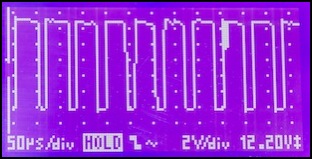
DZ125 PWM Output, showing base pulses
In the photo above, my DZ125 has about a 65 micro-second cycle time on its PWM, which means it’s operating about about 15.4 kHz (my scope isn’t necessarily very accurate, and I’m eyeballing the frequency, so there could be a lot of error in that, the actual frequency is somewhere between 15 kHz and 16 kHz). I’ve seen a similar frequency on a TCS decoder.
Torque
Torque is rotational force. In a motor, it is the characteristic of a motor that performs work, such as pushing a train along a track. In a motor, torque depends on current, and its action against the fixed magnetic field. In a motor driven by PWM during some intervals there is no current (since the pulse is “off”) and as a result, less torque is generated by the motor. Also, if BEMF is being measured directly from the motor, the current will be off while this is being done (likely for a longer interval than the usual gaps between PWM pulses) and thus no current is flowing, and no torque is being produced.
When high-frequency pulses (“supersonic” PWM) are used one consequence is that there is less torque at low speeds, due to “switching loss” in the transistors producing the PWM, which rises with increased switching frequency.
When BEMF is added, it will compensate for the loss of torque by boosting voltage at lower speeds, but it can’t really help much at higher speeds, and could become counterproductive.
In short, PWM alone reduces the maximum motor torque compared to operation on DC, and while a BEMF-sensing control system can boost voltage (which boosts current) to compensate at lower speeds, this is somewhat sabotaged by the sensing process itself, and the maximum torque will ultimately be less than on pure DC.
BEMF is one way, not the only way, decoders can compensate for PWM’s reduced torque, and apply more torque when needed most, at lower speeds. Other methods, known by different names depending on manufacturer (such as “dither” or “torque compensation”) may be used, although it appears these are less necessary (or perhaps irrelevant) if BEMF is in use.
Value of BEMF
So is BEMF useful? My experience indicates that it is. With a ten-car N-scale passenger train driven by a small flywheel-equipped motor, speed up a relatively short (50”, 1.2m) 2% grade dropped roughly 50% more with BEMF turned off than with it at a default setting. The test wasn’t exact, and the grade too short for a detailed evaluation (the train was longer). But at least in my application, that’s a significant performance impairment that’s not at all prototypical for a short train on a relatively mild grade (mild in model terms, assuming there’s some scale compression in the length; in the real-world 2% is a fairly severe grade for a mainline, although not that uncommon).
So yes, I think BEMF is very useful.
BEMF Control
The Back EMF-based control feature in a decoder, “BEMF” for simplicity, is a motor-speed control feature that uses Back EMF to determine the speed of the motor, so it can decide if it needs to change the supply voltage in response in order to return the motor to the desired speed. This is a software algorithm in the decoder that makes decisions about when and how to react to changes in the perceived behavior of the motor, and then reacts by increasing or decreasing the average voltage to the motor (using more or fewer PWM pulses).
Based on my reading (see the References section if interested) it seems that the way to sense speed when a motor is not equipped with an external sensor is to turn off the drive power for a brief time and monitor the voltage produced by the free-wheeling motor (or one of several methods that all seem to work similarly). The decoder has to wait a while, as the motor won’t develop its own voltage until the existing field in the armature windings dies down. As noted above, this too has implications for the motor’s ability to perform work since it’s not producing any torque when the decoder’s driving voltage is off. While some DC motors are equipped with speed sensors, I’m not aware of this kind of motor being used in any model train, nor have I seen any DCC decoders equipped with connections for such a sensor, so the “pause and measure” approach is probably used by all decoders with BEMF-sensing capabilities.
The following oscilloscope trace appears to show this happening (although I’m not 100% sure that’s what it’s showing, it looks “right” for how I’d expect this to work). The pulses stop, there’s an interval when the voltage is at zero (magnetic field inside the motor is dying down) and then the motor starts producing a small (2-3 volts) voltage after 125 microseconds (which happens to be the time constant for this particular motor, so that’s confirmation that I’m seeing what I think I’m seeing), and then after a time long enough for the decoder to be sure it has a good reading the decoder resumes sending PWM pulses. A bit over 300 microseconds were lost to this, which isn’t very much at all.
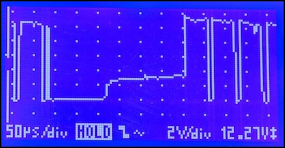
PWM Paused, with motor developing voltage after ~125 microseconds
Once a speed change is sensed (based on the amount of voltage measured during the quiet interval), the decoder then increases (or decreases) the voltage applied to the motor (changes the PWM pulse length) to attempt to return it to the former speed. A decoder without BEMF always sends the same average power (PWM duty cycle) for a given throttle setting, and if load changes the speed of the motor will change. In that case, the human holding the throttle has to see the train slow down (or speed up), decide there’s a problem, and adjust the throttle (and if there is “momentum” configured in the controls, wait for the updated command to be fully applied). This is called an “open loop” control system because there’s nothing “closing the loop” from the motor back to the controller (other than the human turning the throttle knob). A closed-loop feedback control system on the other hand can be reacting hundreds or thousands of times a second, making very minor adjustments in the PWM duty cycle (and hence the power to the motor) to keep things operating as desired.
BEMF Algorithm and Tuning
Implementations of BEMF vary between manufacturers, but are likely all similarly designed. The NMRA defined CV10 (“EMF Feedback Cutout”) as an optional CV to control BEMF. Given the name, this was probably intended to be used to disable BEMF at higher throttle settings. Most manufacturers don’t use this at all, and there’s no standard for how BEMF is supposed to work or what adjustments are to be implemented. In short, aside from suggesting it was a useful feature, the NMRA hasn’t provided any guidance, so manufacturers have all done it slightly differently.
BEMF could simply be an on/off feature (and some decoders work that way). But that presumes that the decoder’s designers anticipated all possible combinations of motor, drive train, and operating environment. A feedback control system has to determine if a change in its input (what it is using for feedback) is large enough to be significant. Then it has to apply a change to its output (and decide how large a change to apply). And finally it needs to give the change time to work before deciding if it needs to apply more, or reduce what it applied. If the decoder acts too quickly or too strongly, it can apply too much voltage and overshoot the desired speed. If it acts too slowly, or too weakly, it can take a long time to return the motor to the proper speed. Some decoders allow the control system (the algorithm) to be “tuned” to ensure that it works well with the specific characteristics of a given model (the motor, drivetrain and load).
DC motor speed control can be done in several ways, but the typical one that’s used for a variety of applications is called PID, which stands for Proportional, Integral, and Derivative (and aren’t you sorry you asked?). Ideally it would be possible to adjust the three aspects of the algorithm (the P, I and D parts) to tune the control to a specific system.
There’s a description of Back-EMF and some comments about how the algorithm works (as well as notes on a number of decoders) on this site, but note that not all decoders may work this way. I didn’t find it all that helpful though, except as a pointer to manufacturer information (which itself isn’t all that helpful). The wikipedia article cited above was more helpful. The basic idea stated there appears to be correct however, which is that the Back-EMF algorithm wants to keep the speed in a range centered on the set speed. The tuning values can adjust how wide that band is, how aggressively the algorithm makes changes when needed (how big the change) and a third adjustment to allow for differences between the actual speed and what reading the current of the motor implies. That is in agreement with other sources I’ve seen that describe Back EMF more superficially, as well as with other descriptions of PID control I’ve read.
The general approach to tuning described on that page mirrors that described by Digitrax (see below): increase the numbers until the train acts funny, than back off a bit, so that you’re getting the maximum benefit from the Back-EMF algorithm without causing erratic operation. It’s all a bit more subjective than I’d like, but as a general rule for tuning a control system it makes sense.
When using BEMF with two separate locomotives (or in my case, motor-cars) consisted, you can get in a situation where the two control systems wind up fighting each other, which leads to “jumping” or “surging” as individual motors speed up or slow down erratically. Reportedly, careful tuning of BEMF parameters can minimize this, or cause it to occur at a speed outside the normal operating range. That’s something I’ll have to look into for some of my 10+5 EMU sets that include two motor cars, but for now I’m focusing on non-consisted BEMF as that’s what most of my trains need.
Generic PID Tuning
There are three constants (which I’ll call P, I and D here) that can be adjusted to alter the behavior of a PID algorithm. See the wikipedia entry’s section on PID tuning for complete details.
Increasing P will make the control react more strongly for a given amount of speed loss, but if set too high the output will oscillate between too high and too low. Note that in a DCC motor control application, the desired setting of this value is going to depend on the amount of motor speed change that can occur due to environmental conditions, and thus it depends on both motor power and the conditions acting on the train (e.g., friction loss in the drivetrain, as well as number, weight and rolling resistance of cars, and maximum grade).
Increasing I will make the control react more strongly the longer the speed is away from the desired setting, but like adjustments to P setting this too high will cause the result to overshoot the desired speed, also resulting in oscillation.
Finally, increasing D will limit how often the system changes the amount of correction being applied. This has the effect of reducing the effects of overshoot, and making the motor settle more quickly to a desired speed. However increasing it also limits how quickly the control can react in the first place, so it needs to be balanced between the extremes. Also, setting it too high can cause the system to become unstable (react erratically and fail to settle on the proper speed).
Some or all of these can be estimated, and while the resulting behavior won’t be optimal, it could be acceptable depending on how well the situation (motor, drivetrain and operating environment) lines up with the assumptions used to estimate the parameters. A more sophisticated control system could probably also adjust these over time to “learn” values that work well (return speed to desired quickly and with a minimum of oscillation).
There’s a fourth value, called “droop”, used to adjust the steady-state behavior of the system (i.e., if it’s stabilizing at less than the desired speed, a bias may need to be added to compensate for droop).
For manual tuning, the guidance is to increase P (with the other values at 0) until oscillation occurs, then reduce it to half of the value that caused the problem. Following that, I should be increased until the control system is beginning to react to changes “fast enough” but not to the point where it causes instability. Finally D should be made non-zero if the speed is not stabilizing quickly enough, but setting it too high will cause instability (and leaving it zero may be fine; it’s a relatively small optimization).
Note that DCC decoder adjustments may not be directly altering the P, I and D constants, and so this guidance may not be correct for a given decoder.
Digitrax BEMF
Digitrax FX3 decoders (those whose model numbers end in 3, 4 or 5) call their feature Scalable Speed Stabilization, and use three variables, static compensation (CV55, default 128), dynamic compensation (CV56, default 048) and Speed Stabilizer-Droop (CV57, default 006). See their knowledgebase article or their Mobile Decoder Manual (PDF) for information about how to tune this. Most online information concentrates on the last CV, and in particular with problems when using BEMF with consisting and how to set this variable to deal with that.
My experience (with a limited set of equipment and decoders) is that for a Digitrax decoder, turning off BEMF results in significantly poorer behavior, and a much higher throttle setting required to get the train moving. That’s with other features (Start Voltage, Tubo Boost) enabled, and there isn’t anything else that would improve low-speed running (other than more voltage via a speed table, which is the same effect as turning up the throttle). Lack of BEMF also results in an exaggerated affect on speed from even relatively mild grades with a small train.
Digitrax’s description of their control algorithm make it sound like a PI algorithm (it could be PID with D set internally) augmented with a droop bias, with CV55 corresponding to P and CV56 corresponding to I. PI isn’t quite as good as PID (it reacts slower), but may be adequate for this application, and certainly the Digitrax BEMF seems to work fairly well.
Although the throttle has at most 127 steps, the FX3 implementation of BEMF-based control actually works with 255 or more discrete motor speeds (the DZ125 documentation says 1024 for that decoder, but most others including the DZ125IN say 256). This provides a fine degree of control over the behavior of the motor that is likely of benefit at lower speeds (although as noted above this may be somewhat limited by the decoder’s internal clock speed). For a typical model, that means about one scale mph or less between motor speeds.
In short, Digitrax’s recommendation for tuning their algorithm is to start with CV57=5 (from the factory, current decoders come with CV57=6, which is probably equally good), which enables BEMF-based control and sets it to a mid-range value (possible settings range from 0-15, with 0 meaning off). There’s a table of the CV57 values in their latest decoder manual (1/2014 edition), but it’s basically a 0 - 100% scale, in equal-size steps, with 0 = 0% and 15 = 100% (for non-consisted operation, the other half of the CV is used similarly for consists, but unless you’re familiar with computers and bit values, see the table in their manual).
With that set, and running the train at about 20% throttle, increase CV55 from 128 until the loco starts to “jump” when the throttle is advanced to the next speed step, then backing off CV55 by one (i.e., one less than the value causing jumping). In practice I couldn’t get that to happen with two different trains and two different decoders; both ended up set to 255, and this may be more of an issue with models that have more play in the drivetrain; my Kato models use a mechanism with very little “play” between motor and wheels. It’s also unclear why this is merely backing off by 1, rather than to half the value that caused the problem (perhaps it’s not really P, or it’s not directly setting the P constant).
With the value chosen for CV55, repeat the process with CV56 starting from 48 until “oscillation” occurs when advancing the speed step, then back off by one. Note: despite this advice, Digitrax also suggests that CV56 should be set to the lowest value “that gives the desired performance”, not the highest that doesn’t cause a problem (these might simply be different ways of saying the same thing). Again, my decoders ended up at 255 with no problems observed.
Then repeat the process again with CV57, advancing to 6, and so on (up to the maximum of 15) and backing off when erratic behavior occurs on an increase in the throttle speed step. A slightly different description in their decoder manual says to increase this until the train isn’t observed to slow going up a hill (and that seems more reasonable to me).
CV57 can be set separately for consisted and non-consisted operation (the above is for non-consisted, with Back-EMF disabled when consisted). This is done on a high-byte/low-byte method, so setting CV57 to 5*16+5=85 is setting both types to 5. Put another way, if you want a consisted train to act the same as a non-consisted one, first configure it and determine the value you want for CV57 (call that “N”), then when you’re done, set CV57 to Nx16 + N (or 17xN) and both consisted and non-consisted trains will have Back-EMF act the same. If you get problems with consisted trains, you can back off CV57, e.g., from Nx16+N to (N-1)x16+N. Note: the decoder manual talks about “first digit” and “second digit” in a very confusing way that seems to say that the high byte is for non-consist addresses and the low byte is for consists, but several other sources (theirs and others) give the explanation detailed above.
Note: I’ve seen some older Digitrax documentation that suggests that Back-EMF is off by default (it’s “on” for decoders I’ve checked), with CV56 and CV57 both set to zero. This may depend on the specific decoder or decoder generation in use.
I’ve seen a couple of online posts suggesting that the operation of BEMF may require either enabling basic speed tables (putting a non-zero value in CV05) or enabling the 28-step speed table (via the bit in CV29, after properly setting CVs 55-95). I think the point they’re getting at is that for BEMF to work, it has to be able to apply more voltage when needed. That means that if you already have the throttle turned up to 100% (or close to it) even if BEMF is turned on, there’s no way for it to increase power. By setting a maximum speed with a speed table, you guarantee that the decoder will never try to send more than X % of the power to the motor without a load, leaving the excess for BEMF to use with a load. You probably want at least 20% headroom (although that’s something of a guess), so setting top speed to around 200 or less (out of 255) in CV05 or the top-end of the 28-step table (CV94) is a good idea.
For consists, the general advice online is that you want BEMF enabled, but at a lesser amount than for non-consisted. A couple suggested using half the value of CV57 for a consist as you do for non-consisted, so if CV57=6 for a non-consisted configuration, set it to CV57=(16*3)+6=54to extend it to apply to consists at half-strength. The number 54 is represented in hexadecimal as 0x36; and as you can see, using hex makes it easier to see and set the two halves of the CV, if your programmer allows this.
Lenz BEMF
Lenz’s Silver Mini+ supports Back-EMF tuning via CV9, CV113 (minimum PWM value) and CV114 (change duty cycle), if motor type 4 or 5 is selected (in bits 0-3 of CV50, see manual). CV50 is also used to select which kind of Back-EMF to use (high efficiency motor or normal) or to turn it off. Setting bit 6 of CV50 (high-efficiency motor) will allow some motors to run at higher speeds, but the cost is that they won’t run at as slow a minimum speed. These values sound more like adjustments to PWM itself, rather than to a control algorithm, and so they may be independent of BEMF.
According to a set of posts by Martijn on the JNS forum (recounting some info from German-language websites and documents), the motor type is just a number, and the guidance is to “pick the one that works the best” for a given locomotive. The repetition rate should be “lower” for older and lower-quality motors (lower-quality may mean 3-pole in this context) and higher for newer/better ones. There’s an English-language manual on the German website (PDF, pointed out by Don on the forum) that provides some detail (but doesn’t really explain anything). However it’s for the older “Silver” design (and not specific to the Mini version) so it may not be entirely applicable to the current “plus” version of the Silver Mini.
Lenz USA now has a page on their website about Back-EMF, although it doesn’t say how to tune it either. This notes that the maximum speed step (I think they mean CV5, Maximum Speed, as they say “register five”) needs to be set to limit the model to a prototypically maximum speed for the best results. They also note that when used with a speed table, each step in the table should be 1.2 times the previous, with the average speed around steps 16 to 18. They also note that it’s common to turn it off at higher speeds, so that trains will slow down on grades the way prototypical ones would, requiring the “engineer” to compensate manually, the way a real engineer would.
TCS BEMF
On TCS decoders, BEMF is on by default, does not require (or allow) tuning, and can optionally be set to cut out at a specific throttle setting or via a function key.
TCS claims that their Back-EMF doesn’t need to be tuned, and in any case they don’t provide any means to tune it (I find this claim dubious, although it is in line with some other comments I’ve read about PID control generally working, if suboptimally, for fixed settings). It can be turned off altogether by setting CV61=0 (default is 1) or by using a configurable function button (default is F6, but only enabled if CV61=3), and they suggest doing this for low-speed yard switching and when consisted. They also have a cut-out option: by setting CV10 to a number from 1 to 128, Back-EMF will cut out once the locomotive reaches that speed step. CV10 also supports a number of other functions on the decoder, see their manual for other appropriate values. They also have an alternative speed control, called “dither”, enabled only if BEMF is disabled and CV56 and CV57 are set to non-zero values (see their manual).
One of the reasons to use BEMF is reliable low-speed starts, so TCSs guidance to turn it off for yard use, and the implication that they’ve optimized their control algorithm for constant-speed at higher speeds (e.g., when going up grades), seems to me to be a significant count against their motor decoders. From what I’ve read, TCS uses a separate control algorithm (dither) for low-speed use, and gives you an either/or choice of which to use. Which is fine if you’re wiring a switcher or a road loco, I suppose, but it’s not a good choice to have to make for a passenger train that needs to make reliable low-speed platform stops, and run well at high speed. I suspect that if you’re using the CV61 feature above, and configure both BEMF and dither, you’d get the dither effect if you turn off BEMF with the function button, but this places the burden of doing so (and remembering to do so) on the operator.
BEMF and Other Manufacturers
See this writeup for a discussion of PID control used on some QSI decoders.
Other Info
Here are some other useful links:
BEMF vs Dither
Here’s an interesting discussion of the different methods of managing low-speed starts with DCC, including a discussion of just what TCSs “dither” is, and how it relates to BEMF. This is the same page linked above as a reference for PWM frequency. In short, these techniques add a periodic “kick” of extra voltage (meaning a longer or extra PWM pulse) to the motor, to compensate for the lost torque. Unlike BEMF, dither isn’t adaptive. It’s either on or off, and it’s on at a specific preset value. Depending on a lot of factors it could work better or worse than BEMF, but if both are properly designed I’d expect BEMF to work better, and it would seem that in general it does.
References
And some references.
How to Drive DC Motors with Smart Power ICs, by Herbert Sax (SGS Thomson, now ST Microelectronics, 1991 application note AN380: download page, PDF) - This note provides a good overview of the electrical behavior of DC motors, and describes a variety of ways motors can be controlled.
Sensorless Speed/Position Control of Brushed DC Motor (PDF), E. Afjei,A. Nadian Ghomsheh, and A. Karami (2007) - this paper provides an overview of PWM motor control, and outlines a method of sensing speed by counting pulses caused by the brushes breaking contact with the commutator (this also requires briefly turning off the motor drive power).
