


Electric Train and Locomotive Propulsion
There are many different systems for propelling electric trains, beyond the obvious distinction of using a separate locomotive or distributing the propulsion systems throughout the train. All of these are similar in that power is drawn from an overhead line (or in a few cases a third rail), run through various systems to control it, fed to electric motors connected to the wheels, and eventually returned to the rails as the “ground”, or return path. And in most but not all cases in Japan, the power source used by the train is 1,500 volt DC.
The discussion on this page will largely focus on the trains and railway lines of Japan’s Kantō region, which includes Tōkyō, as this is the area of focus for my modeling. However, much of what is covered here is applicable to other regions of Japan, or to electric railways in other countries for that matter.
Unlike catenary, which has distinctive appearances for AC versus DC systems, the type of propulsion system used is not visible on a model railroad, except perhaps in some minor details on train models. But there is one significant characteristic: sound. As N-scale model railroad sound systems become more widespread, understanding the reason why some trains sound different becomes more important when modeling them, particularly when modeling a train for which no exact prototypical sound system is available.
Types of Power
Shinkansen (“bullet train”) lines typically use 25,000 Volt AC at either 50 or 60 Hz (and the Nagano Shinkansen has sections using each frequency). The reason for the two different frequencies is that western Japan uses a 60 Hz power grid, while northern Japan uses 50 Hz, and the railroad uses the same frequency to allow it to draw power from the grid, although some railroads also operate their own generating stations. Tōkyō is on the 50 Hz grid, and lines in and near the city thus use that frequency, with the exception of the Tōkaidō Shinkansen, which apparently uses 60 Hz power along its entire route (most of which is on the 60 Hz grid) including at the Tōkyō end.

DC-power Catenary (wire) and E231 Pantograph (2010)
Photographer: toshonori baba
In general, AC power is preferable to DC power for long-distance transmission (see the Catenary page for more on this), and systems using DC power require more frequent substations where AC from transmission lines is converted to DC and delivered to the catenary wiring. For this reason, most long-distance railroads around the world use AC power on the catenary itself. Japan’s non-Shinkansen lines aren’t the only long-distance railways using DC catenary, but it’s not very common elsewhere.
Most electrified Japanese lines other than Shinkansen use 1,500 Volt DC power, but there are a few exceptions. The northern section of the Jōban line uses 20,000 Volt AC at 50 Hz, and the outer section of the Tsukuba Express Line, which parallels the Jōban line, does as well. Both of these use AC starting about 45 km from Tōkyō, and the reason is the same: the Japan Meteorological Agency’s Geomagnetic Observatory (Japanese wikipedia). Due to the effect on observations made at the station, DC-powered railway systems are prohibited within a 30 km radius. When it came time to electrify the Jōban line, AC had to be used north of Fujishiro (46 km from Ueno Station). The Tōhoku Main Line, which parallels the Jōban line along a more inland route, passes far enough from the observatory that this is not an issue, and uses DC in this region. However, beyond Kuroiso 163 km from Tōkyō it, too, switches to 20kV AC power for the remainder of the route to the present end of the line at Morioka.
There are other DC systems in use. Although most subway lines in Tōkyō use 1,500 volt DC from overhead lines, the first two subway lines built there, the Ginza and Marunouchi lines (both operated by Tōkyō Metro), use 600 Volt DC third-rail power. The use of 600 Volt DC is also typical of light-rail lines. Both the Nippori-Toneri Liner (a fixed-guideway system, rather than a rail line) and the Toden Arakawa tram line use 600 Volt DC from overhead wires. These are operated by the Tōkyō Metropolitan Bureau of Transportation, a.k.a., Toei, which also operates many conventional 1,500 V DC overhead-powered lines, as does the Tōkyō Metro. And the Tōkyū Setagaya Line (in Tōkyō’s Setagaya ward), as well as the Enoshima Electric Railway (a.k.a., Enoden) tram line between Kamakura and Fujisawa (both just south of Tōkyō) uses 600 V DC from overhead lines.
Finally, 750 Volt DC is also used in Japan. The Yokohama subway Blue line uses 750 V DC (but the Green line uses 1,500 V DC), as do a number of railways in other parts of the country (note that the English Wikipedia page for the Blue line claims it is a 1,500 Volt DC line, but the Japanese Wikipedia page says 750 V DC).
In Japan, 22 kV three-phase AC transmission systems are one of the common ones used, and as used by the railways these provide for 20,000 volt single-phase AC outputs, which is likely the reason this voltage was used in several places. This is also the voltage used as a transmission-line voltage by 1,500 V DC railways, to send power to the step-down transformers and rectifiers that provide the 1,500 V DC power to the line (reference: Japanese Wikipedia).
Note: utility power transmission is typically three-phase, and uses three wires. Most catenary uses a single wire, and with AC this carries single-phase power (the return path is via the rails).
Distributed versus Centralized Motors
In the days of steam, trains were (usually) hauled by a separate locomotive, as it was not efficient to install a boiler in each car of the train, nor was there any way to synchronize their operation. Diesel trains had much the same limitation originally, although multiple-unit controls were soon added so that several adjacent locomotives could be controlled by one engineer.
With electrically-powered trains, there was no separate power source (other than the power pickups and non-mechanical devices such as transformers), and it became practical to distribute power (i.e., the motors driving the axles) throughout the train. This was also more efficient, as each pair of wheels could contribute a smaller amount of motive force for the same result, resulting in less slippage of the wheel on the rail (and thus permitting higher acceleration, an important feature on urban lines with frequent stops). The development of small but powerful diesel engines made it possible to to the same thing with non-electric trains.
Trains with such distributed power are known as “Electrical Multiple Unit” (EMU) or “Diesel Multiple Unit” (DMU) trains. Most commonly only a subset of cars in a train are equipped with motors. In JR East commuter EMU designs, typically four cars of a ten-car train will be powered (known as “motor” cars) with one motor per axle, and the other cars unpowered (known as trailers). Additionally, it is common for two motor cars to share a pantograph (rooftop power collector), thus in a train with a 4M6T set of cars (four motorized, six unpowered trailers), there may only be two pantographs.
Most “diesel” trains are diesel-electric, and use the diesel engine to drive a generator, which provides power (through the control system) to electric motors on each axle. The ubiquitous DE10 is an exception, being diesel-hydraulic, meaning that there is a mechanical transmission between the motor and the wheels. With DMUs, typically there will be one generator per powered car, providing electricity to four wheel-mounted motors (one per axle). Thus both EMUs and DMUs (and most electric and diesel locomotives) have electric motors, and the control systems to drive them.
In locomotives, while it is common for all wheels to be powered, this is not universal. A few six-axle Japanese locomotive designs use three sets of two-axle trucks, with only the two end sets powered. These include the ED76 (electric) and DD51 (diesel) locomotives (note that the second letter of the class refers to the number of powered axles, not the number of total axles, thus “D” is used for these even though they have six axles each). Others, such as the EF210 power all six axles.
Traction Motors
Modern electric trains typically use AC motors (a typical one of the type used by the E231 is described on this Japanese Wikipedia page), even when the power supply is DC, although this is a recent development. This is because AC motors provide better tractive effort (use of available motive power), although they are more complex to control. Older trains used DC motors, which were typically half as efficient (i.e., with locomotives, two DC-powered locomotives of a given horsepower each are typically replaced with one AC-powered locomotive of the same horsepower). AC motors are similarly efficient at regenerative braking, meaning they can more effectively brake a moving train, allowing more power to be returned to the electrical system.
AC motors also require substantially less maintenance than DC motors, as they lack brushes that need periodic inspection and replacement, and commutators. Reportedly (see JRTR article in references) this halves the maintenance requirement.
The electric motors used in trains are typically located adjacent to the axle they power, on the assembly (the “truck”) holding the wheels. This makes the power transmission system nothing more than a simple gear. A number of different motor designs have been used over the years (see this Japanese Wikipedia page for a list):
Passenger Train (EMU) Motors:
MT55: DC, 110kW series-wound
MT60: DC, 150kW compound-wound
MT61: DC, 120kW, series-wound
MT68: AC, 95kW, squirrel-cage, three-phase induction
MT73: AC, 95kW, squirrel-cage, three-phase induction (regeared MT68)
MT75: AC: 140kW, squirrel-cage, three-phase induction
MT77: AC. ???kW permanent-magnet, squirrel-cage, three-phase induction
Locomotive Motors:
MT52: DC, 425kW, series-wound (increased to 475kW on EF67)
MT56: DC, 650kW, series-wound
FMT1: AC, 1,000kW, squirrel-cage, three-phase induction
FMT2: AC, 1,000kW, squirrel-cage, three-phase induction
FMT-4: AC, 590kW, squirrel-cage, three-phase induction
FMT130: AC, 220kW, squirrel-cage, three-phase induction (used on M250)
Note: above motor type and ratings taken from various Japanese Wikipedia pages for the locomotives and trains that used these motors. Some motors are rated for short-term loadings, and have slightly lower kW ratings in continuous use.

Series-Wound MT61 120kW DC Motor from a 205 EMU (2009)
Photographer: Hanabi123
Controlling the Motors
Power cannot be fed directly to the motors, there needs to be some method of control. In the earliest systems, DC power from the catenary was fed through a grid of resistors, and a lever system allowed the operator to vary the amount of resistance (and hence the drop in voltage). DC motors turn at higher speeds with higher voltage, so this provided a fairly primitive, but effective, method of control. Eventually the lever was replaced with relays, which allowed one operator to control multiple voltage-control systems distributed through a multi-unit train. In the most modern trains, computers and a control network have replaced the relays, but ultimately a high-voltage system still needs to control the power to each motor.
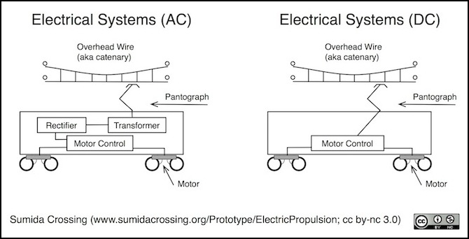
Simplified Summary of Elements of Electric Train Propulsion Systems
More complex systems also evolved, including the use of AC power in the overhead wires, which needed to be stepped down to a usable voltage via a transformer, and converted to DC via a rectifier, before it could be fed into the same control system. This made for more complex arrangements, but the benefits of AC transmission (reduced wastage of power and fewer substations) made it worthwhile. Outside of a few lines, and the long-distance Shinkansen, Japan never made this change. Perhaps in part because the high volume of use in metropolitan areas required frequent substations and shorter transmission distances anyway, and the additional equipment required on the numerous trains represented a substantial cost.
Finally, the introduction of AC-powered motors brought a need for new control systems that could produce variable-frequency AC power (unlike DC motors, AC motors are controlled by varying the frequency of the AC, as well as its voltage).
DC motor control systems went through three basic stages: resistor-based controls, “chopper” controls, and the more sophisticated “magnetic field excitation control” approach. Note that the power supply is to an extent independent of the power transmission system: the first Shinkansen used DC motors with an AC catenary, and earlier commuter trains used all-DC systems. Modern trains use AC motors with both AC and DC catenary. This also facilitated the construction of “dual mode” trains that could run under both DC and AC catenary.
DC Motors used in trains were originally controlled by varying their current through the use of switched resistors. As motor speed increases, resistors are removed from the circuit. Because these resistors dissipate a large amount of power as heat this is a very inefficient approach. The simple form of this approach also discards power (as heat) during regenerative braking, which is very inefficient in an urban railroad with frequent stops.
In the 1970’s Japan National Railways began developing a more sophisticated DC motor control. At that time, AC motors were in use on Shinkansen, but the technology did not exist to make their use on DC-powered lines practical. In 1979, the 201 Series was introduced with a simple “chopper control” system based on the use of high-power thyristors. This produced pulsed DC power, essentially the same as the PWM output by a model train DCC decoder, and avoided wasting energy as heat. The problem with this approach was that it required the use of a more expensive compound-wound DC motor.
Later, a more sophisticated “magnetic field excitation control” system (Japanese wikipedia) was introduced with the 205 series, which allowed a return to the use of series-wound DC motors and parallel-resistor voltage controls, while still permitting regenerative braking to return power to the grid.
The use of AC motors on DC-powered lines also became practical with the development of high-power semiconductors (thyristors, and later transistors) in the late 1970s, although these did not become common on Japanese railways until later. To control an AC motor, the voltage and frequency of the AC provided to it must be adjusted to control the motor speed (on AC lines, the single-phase power on the catenary must also be converted to the three-phase AC used by the motors). This is done by means of a type of inverter known as a Variable Voltage, Variable Frequency (VVVF) inverter. This inverter feeds power to output devices that act as switches.
These switches went through several generations of development, although the earliest (non-GTO thyristors) doesn’t appear to have been used in Japan (unless that’s what a “copper control” is, I haven’t found a good reference for that). Early thyristor designs were not very efficient, and were soon supplanted by the Gate Turn-Off (GTO) thyristor, which in turn was replaced by the Insulated-Gate Bipolar Transistors (IGBT) when high-power transistors were developed.
The distinctive sound of electric trains comes in large part from the characteristics of these output devices, and their operating frequencies. GTO thyristors have a rising frequency at start-up, and a descending frequency as the motor reaches full speed, but otherwise tend to operate at a fixed frequency. The IGBT tends to remain at a single frequency.
Hitachi has developed (as of 2012) a new hybrid silicon cabide inverter “combining silicon carbide diodes and silicon insulated gate bipolar transistors” which is reported to be more efficient than simple IGBT. It’s unclear when these will start showing up in new vehicles, or what they’ll be called, or whether they will sound different than IGBT. Hitachi refers to them as “SiC hybrid”.
Trains and Control Systems
103 Series (Japanese Wikipedia): 1963, Series-wound MT55 DC Motor with parallel resistor control
201 Series (Japanese Wikipedia): 1979, Compound-wound MT60 DC Motor with chopper control
205 Series (Japanese Wikipedia): 1985, Series-wound MT61 DC Motor with magnetic field excitation and parallel resistor control
209 Series (Japanese Wikipedia): 1993, VVVF inverter with GTO (except 8-series 209’s, which used IGBT) with MT68/MT73 motor
EF210-0 (Wikipedia): 1998, VVVF inverter with GTO and FMT-4 motor
EF210-100: 2000, VVVF inverter with IBGT and FMT-4 motor
E217 (Wikipedia): 1995, VVVF inverter with GTO (pre-2007) with MT68/MT73 motor
E217 (Japanese Wikipedia): 2007, VVVF inverter with IGBT (post 2007 update), with MT68/MT73 motor
E231 (Japanese Wikipedia): 2000, VVVF inverter with IGBT, MT73 motor
E531 (Japanese Wikipedia): 2005, VVVF inverter with IGBT, MT75 motor
E331 (Japanese Wikipedia): 2006, VVVF inverter with IGBT, but with permanent magnet direct axle MT77 motor
Note: for some reason Google sometimes (not always) translates the kanji “直流” (direct current) as “Ryuu Tadashi”, so when reading translated wikipedia pages, that phrase should be read as “DC”.
Sounds
There are distinctive sounds to the various control systems, and these vary depending on the manufacturer (and possibly other causes) so trains with the same basic mechanism do not all sound the same. DC motors tends to produce a smooth hum, rising in pitch as the speed increases. AC motors tend to produce various kinds of high-pitched sounds, that vary depending on both rate of acceleration and speed.
The following links provide some representative examples of each type.
Sagami line 205-500 video with Series DC motor and magnetic excitation sound.
Keikyu N1000 video with VVVF/GTO sound. This train has a characteristic “musical” sound.
JRF EF210-0 video with VVVF/GTO sound.
JRF EF210-100 video with VVVF/IGBT sound. Note the difference from the EF210-0.
Chuo Line E231 video with VVVF/IGBT sound. This has a higher-pitched “singing” sound than the EF210.
JR Kyushu 885 (“white seagull”) video with VVVF/IGBT sound. This is closer to the E231, but not quite the same.
References
AC Traction vs DC Traction article (Republic Locomotive).
Hitachi press release on Hybrid IGBT.
What Drives Electric Multiple Units?, by Hiroshi Hata, JRTR No. 17 (Sep. 1998), pp 40 - 47.
Wikipedia pages for Electric Locomotive, Traction Motor and Induction Motor.
