


Detecting Trains with IR Sensors, Part I
In my continuing work on the Arduino-based Tram Controller, I’m now playing around with the part I really wanted to work with, the Infra-red optical sensors themselves. This turned out to be rather more complex than I’d anticipated, but I’m most of the way there, even if I don’t quite have the system working yet. This is a post about what I’ve done so far, and what I’ve learned, with a bit about what remains to be done.
But first, I want to mention that I’ve created a category, Tram Controller, for all of these posts related to that project, so you can find all of this material easily. In addition, I also have the pages describing the work under a Tram Controller page in the Electrical Systems subsection of the Model Railroad section. Those will be kept up to date, while the Musings form a record of the development of the project over time.
So, to the sensors: the basic idea I started with is that I want to use an Infra-red LED light source and an Infra-red-sensitive phototransistor to detect when the tram enters a station or approaches a switch where I might have to stop it. These are both places you might expect the driver to see a signal and stop, and I’m effectively controlling the throttle in the same way that a driver would react to a signal. In fact, I could also control trackside signals with the same information, but for now I’m just going to use this to control the throttle.
Hardware and Design
I’m using the Digikey 160-1065-ND & 160-1063-ND, which are Lite-on LTR-301 phototransistors and LTE-302 infrared LEDs, respectively. These are less than fifty cents each in bulk from Digikey, or about twice that sold in emitter/detector pairs for US$2 from SparkFun.
These come in a vertical arrangement that’s 5.72mm high, 4.40mm wide, and 1.50mm thick (or less than 1/4 inch tall). The active portion is on the side, so you can stick the pins down through the ground cover (or a base of some kind) and the LED will fire horizontally across the track at the receptor on the phototransistor. There’s a color-code on the top (yellow on the LED, red on the phototransistor) so you can tell them apart, and a bump on the side, so you know which side is active. I plan to paint the non-active portions silver, and disguise them as trackside electrical cabinets, but I haven’t gotten to that yet. I’m also thinking about maybe putting something on them to limit light from the fluorescent fixtures above the track from hitting the active portion, more on that below.
The LED (LTE-302) works just like any LED. It has a forward voltage of 1.2 to 1.6 volts at 20 mA, and a maximum amperage rating of 50 mA. A reverse voltage greater than 5V will “let the smoke out” (i.e., destroy them). I’m wiring these up in strings of four with a 330 ohm, 1/2 watt resistor off one of my regulated 12V DC supplies (like this one), which runs them at about 30 mA.
The phototransistor (LTR-301) is the interesting part. This needs a voltage source, which can be up to 30V (I’m using 5V since that’s what an Arduino pin puts out), and when activated by infrared light falling on the sensitive portion will pass somewhere between 0.6 mA and 2.4 mA at full strength (the variation in current among individual sensors is one thing I need to deal with in my software, since it affects the level read by the Arduino).
And I plan to read these using an Arduino’s Analog pins. Since I have eight sensors, and most Arduinos are limited to six analog pins, I want to “multiplex” these, so one pin can read multiple sensors. This should be fairly straightforward (and in the end, it was, but the journey was an interesting one).
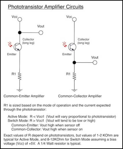
There are a number of ways to use phototransistors, but they’re all essentially methods to make charge from the +5V source (Vcc in the diagram below) back up behind a resistor or the phototransistor where it can be read as a voltage at the Vout point of the circuit. Two of the most common are shown below, I’m using the one on the right.
With that arrangement, light on the phototransistor allows the +5V from VCC through, but the resistor prevents it from immediately going to ground. This creates a voltage (relative to ground) on the wire between the resistor and the photodetector. Since Vout is connected there, reading this with an Arduino will measure that voltage, and the Arduino will report it as an integer from 0 (0V) to 1023 (5V). Higher numbers mean that more light is falling on the phototransistor (i.e., that there isn’t a tram in front of it).
My final working design is shown in the circuit diagram below. This connects four sensors to two analog pins, which is all I need. However this design will work equally well for more sensors per pin, and for more analog pins. There’s likely a limit on the number of them you could put on one analog pin that’s smaller than the number of available digital pins. And increasing the number of analog pins requires adjusting the “safety resistor” value to allow more current through (more on that below). But ultimately, the limit on the number of sensors is going to be due to software processing speeds more than anything, I think.
Now this is really more complicated than it needs to be, since I wanted to solve the general problem of multiplexing. In truth, I could have used eight digital pins, each connected to one phototransistor, and connected all of the phototransistors to one analog pin and resistor. It would work the same way, and be even more efficient of analog pins (and I’m not going to run short of digital pins). But this is how I did it, at least for now.

How this works is that L1 - L4 (the LEDs) are always on, shining at the adjacent photodetectors. But D1/D2 (the digital pins on the Arduino) are usually in the LOW state, meaning that they’re grounded and not providing voltage to the collector side of the phototransistor. With no source voltage, there’s nothing passing through the photodetector when it’s on, and thus it doesn’t add to the charge at the analog pin.
When a digital pin is set to +5V (HIGH state in the Arduino), it provides voltage to one phototransistor on each analog pin (let’s use D1 as the example, it provides voltage to both P1, connected to A1, and P2, connected to A2). As long as the light isn’t blocked anywhere, this allows current through all of the phototransistors connected to that digital pin (P1 and P2) but because transistors (of any sort) are one-way gates, the current can’t go through the others on that analog pin (i.e., P3, P4) to get to the grounded digital pin. It must exit via the resistor to ground. And when it does, it creates a voltage across that resistor.
Each analog pin can then be read to detect the state of its associated photodetector (“on” meaning nothing is blocking the light, and “off” meaning that there’s a train there, or maybe a really big spider).
And you can then repeat this, set D1 to LOW, and D2 to HIGH, and the same analog pins can be read again, this time revealing the state of the P3 and P4 photodetectors.
Note that the “safety” resistors, RS1 and RS2, are just there to protect the Arduino from a short, should I accidentally connect part of the circuit to ground. An Arduino digital pin set to HIGH state and wired directly to ground is likely to blow its driving transistor, forever disabling that pin. I know how easy it is to make circuit mistakes, so I consider these indespensible, although they aren’t required for the normal functioning of the circuit. The ones I’m using allow at least 4x the needed current for one sensor (I = V/R = 5/470 = 0.0106 = 10.6 mA), so even if I had four analog pins wired up I’d be fine. To do more, I’d need a smaller safety resistor.
Analog is Messy
The first problem in this nice simple picture is that phototransitors are analog devices: they don’t actually pass an “on” and “off” signal, they pass a variable current that creates a variable voltage from 0 to 5 volts (in my system). And how it will vary depends on the LED that’s connected, how well the LED is aimed at the detector, what other light falling on the detector and how much of it is infrared (most house lights have a lot of infrared actually), and manufacturing variations in the detector.
Getting into the actual numbers, with 2.4 mA going through the photodiode, the 5 Kohm resistor could drop 12V, which means it would block everything, creating a maximum potential of 5V to be read. With 0.6 mA, it would drop 3V, creating a maximum potential of 2V to be read. So I should expect my sensors to return values between 409 and 1023 when fully lit. I actually get numbers around 700 to 800 on most of my sensors, and around 350 on one, which just shows how different the real world can be.
In fact there turns out to be a LOT of variation. Although I mentioned a “switch mode” above, where outputs tend to be low or high, in practice this appears to require tuning the resistor to the expected light (it shouldn’t, in an ideal world, but I couldn’t get consistent results just by using a large resistor). That’s not really practical for something on a layout with potentially variable light, or reflectivity of the trams themselves.
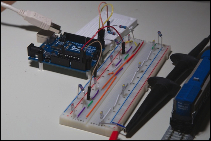
My first order of business was to set up a set of four detectors (that’s it in the photo at the top of the page, LEDs on the right, detectors on the left) and experiment with different values for the R1/R2 resistors. I settled on 5K ohms after some experimentation showed them providing the widest range of variation from low to high under worst-case conditions: I stuck a halogen desk lamp, which puts out a lot of IR, about 18” (0.5m) above the sensors, to simulate very bright incandescent light. That also worked well in much dimmer room lighting, but dim lighting is the easy one. For this test I used a very simple program that read the sensors, printed them out, paused for a second, and then repeated.
Here’s the essential code to read the sensors. Please pardon the lack of indenting; my web software aggressively removes “unnecessary” blanks:
for (outPin = 0; outPin < SENSOR_BANKS; outPin++) {
// activate the bank of sensors
digitalWrite(pwrPin[outPin], HIGH); // turn on the driver for this bank
delayMicroseconds(CHARGE_DELAY); // give it time to stabilize
for (inPin = 0; inPin < SENSOR_EACH; inPin++) {
// read the value
sensorValues[sensNum++] = analogRead(whichPin[inPin]);
}
digitalWrite(pwrPin[outPin], LOW); // turn off the driver for this bank
}
where CHARGE_DELAY=100, SENSOR_BANKS is the number of digital pins, SENSOR_EACH is the number of analog pins, pwrPin is an array of the digital pin numbers (2, 3, etc), and whichPin is an array of analog ones (A0, A1, etc).
In addition I found that I needed to have a delay after turning the digital pin on before I could read the analog pin and get a useful response. This had to be somewhere around 50 - 100 microseconds (I used the latter, as I didn’t need it to be any faster). Longer delays didn’t seem to help. I found that “blocked” readings could vary from 0 to ~600 (on a 0-1024 scale), and that “not blocked” readings were typically around 700-800. The closest the two came to each other was about 120 apart, so I’ve used 100 as the minimum separation that signals a change from occupied to unoccupied, or vice versa. But, of course, it’s not quite that simple.
Along the way I also learned one of the basic Arduino lessons: don’t use digital pins 0 and 1. Even on Arduinos that separate the USB driver to another chip, these still have a relationship with the serial driver, and will change in ways you don’t want them to when USB is connected.
InfraRed is Everywhere
One problem I observed is that most light contains some infra-red light, and normal lights (incandescent bulbs) contain quite a bit. This can swamp the amount of light produced by my LEDs. Because the LEDs are fairly well focused, as are the photodetectors, this isn’t as much of a problem as it could be. And on my layout I may not have any problems, because I’m using fluorescent lighting, which likely doesn’t contain a lot of Infra-red (I need to check that at some point).
But there’s always some excess out there, and I need to compensate for that. Part of what my software does is determine the normal high and low levels, and calculate a “minimum transition” number. Changes smaller than the minimum are ignored, large ones indicate that a detector is moving from occupied to empty, or vice versa.
I may be able to deal with ambient light entirely with software. But I’m considering putting some small shields on the top of my sensors to reduce the amount of room light falling on the sensor’s active area. However, part of the problem is room light reflecting off the side of the tram into the sensor, so the more I think about it, the more I think I’ll need to handle this in software.
Analog is Really Messy
Even when you’re dealing with one sensor, and a constant level of lighting, the value of the sensor will bounce around quite a bit. I saw jumps of 50 or more in some cases. There’s actually a really simple way to deal with this: a digital low-pass filter. And there’s a very simple way to implement this efficiently using shifts and fixed-point arithmetic, rather than division and floating point (which both take a very long time). This does require a careful choice of the “alpha” value used in the filter, but that’s not hard to do.
The digital filter I’m using is called an Exponential Weighted Average filter, and what it does is called Exponential Smoothing. This is like averaging a set of numbers, except that the individual numbers are less and less important the older they get. And most importantly, it only requires two numbers, the current reading and the past average, to calculate the new average. This means I don’t need to store a large number of past readings, just one prior average (well, it’s a bit more complicated than that, but not much: I end up storing just an “intermediate” average for this filter, but I also have to store a couple of past history smoothed result numbers for my high/low detection, which I’ll describe later).
The constant that defines how quickly these fade to insignificance, meaning how quickly the result adapts to changes, is called “alpha”, and is a number between 0 and 1. The larger alpha is, the more quickly the result adapts to changes. For the fixed-point shift-based approach, alpha needs to be the reciprocal of a power of two (meaning 1/2, 1/4, 1/8, etc).
I found an Arduino implementation by Googling around, and finding this site, which explained the issues and timings quite well, although it took me some time to figure out just what his fixed-point math was actually doing. The “fixed point multiplication and shift” used in his example formed the basis of my solution, although I had to adapt it slightly. First, he’s not using the standard Arduino development environment, so some of his code won’t work as-is. Second, he’s implementing a digital filter with an alpha of 1/16 (0.0625), which adapts to changes far too slowly for my purposes. I simplified this to use an alpha of 1/2 (0.5), which adapts much faster. His solution is fine if you only want to get a new sensor value every second or so, but I want to handle changes on a millisecond scale.
I wrote a little smoothing function that takes the read sensor values, and creates a “smoothed” version of them. This tends to ignore fluctuations in the values of the sensor, and mine (alpha = 0.5) responds in a half-dozen cycles to major changes. Since I’m reading all of my sensors about once every 1.5 milliseconds, I can observe changes in about 10 milliseconds. Observing isn’t the same as cleanly detecting transitions from low to high or vice versa, and I’ll get to that in a bit, but first here’s my smoothing code:
long interimStateA[(SENSOR_BANKS * SENSOR_EACH)];
int smoothStateA[(SENSOR_BANKS * SENSOR_EACH)];
int sensorStateA[(SENSOR_BANKS * SENSOR_EACH)];
// perform exponential weighted averaging with alpha = 0.5
void smoothSensors(int sensorValues[], long interimValues[], int smoothValues[]) {
int i;
for (i = 0; i < (SENSOR_BANKS * SENSOR_EACH); i++) {
interimValues[i] = (sensorValues[i] << 4) + (interimValues[i] >> 1);
smoothValues[i] = int((interimValues[i] + 16) >> 5);
}
}
void loop() {
// other stuff like reading the sensors
// smooth what we read
smoothSensors(sensorStateA, interimStateA, smoothStateA);
// do something with the smoothed values
}
The formula implemented here is: smoothn = alpha x sensorn + (1 - alpha) x smoothn-1.
In this code, interimStateA is smoothn-1, the moving average of past readings I store (the array holds one value for each sensor), and because of the way I’m doing fixed point, this needs to hold numbers larger than 32K, so it has to be of type long, even though the sensor readings themselves never go above 1023 and will easily fit in an ordinary int type variable.
It’s a very efficient algorithm, and will process all four sensor readings in about 40 microseconds, which is essentially instantaneous compared to the 700 microseconds it took to read all four sensors in the first place.
With this, I now have readings in “smoothStateA” for four sensors that have the sudden jumps smoothed out. Each time around my main loop I read the sensors (both my A and B banks, for a total of 8 sensors), smooth them, and do further processing, and the full cycle takes just 1.5 milliseconds, meaning I can do it about 650 times per second.
Detecting Something Changed
Now this is the part I’m still working on, but I know how to do it.
The basic idea is that big changes mean an occupied sensor was cleared, or a clear sensor was occupied. Once a change is detected, further changes in the same direction can be ignored. In other words, if going from 200 to 300 changed a sensor to “occupied”, further rises to 400, 500, 600 and 700 can be ignored, and all we need to watch for is a drop from whatever to whatever-100 to detect a change in the opposite direction and move back to “unoccupied”.
Doing this involves keeping some recent history of past sensor readings, and “latching” the fact that we have already made a change in one direction or the other. I haven’t finished polishing this code yet, so it’s not ready to show, but it’s getting there, and I expect it to be very fast.
My expectation is that ignoring time I need every loop to update throttles (which shouldn’t take too long), I’m going to detect a sensor state change no more than 15 milliseconds after it happens. A tram moving a scale 40 kph will have traveled 1 mm in that time. I think that’s reasonably precise.