


IR Sensors
One of the more useful things to connect to an Arduino, at least when working with model trains, is an infra-red optical sensor. This is a device that reports a number that varies depending on how much infra-red light is falling on it. Infra-red (literally “below red”) is light that the human eye can’t see. Some normal light sources, like sunlight and light bulbs, contain infra-red as well as visible light, but for sensors usually a specific source is supplied so that there is a bright source focused on the sensor. When a train, or some other object, passes between the light and the sensor, the number reported drops by a substantial amount, and this can be used to detect the presence or absence of a train.
As with all of my Arduino projects, I’m using Arduinos based on the Atmel processors, i.e., the original, simple, Arduinos like the Uno and Mega, not the newer computer-like ones. I’m also using ones that operate on a 5 Volt power supply, rather than the 3.3 Volt kind. The latter can be handy for some kinds of circuits, but I find having 5 volts to work with, even though they may require more resistors and wasted power. The low-voltage kind are more useful if you need to operate off battery power, which I don’t.
Phototransistor Sensors
I’m using the Digikey 160-1065-ND & 160-1063-ND, which are Lite-on LTR-301 phototransistors and LTE-302 infrared LEDs, respectively. These are less than fifty cents each.
Types of Sensors
The fact that the detector is a phototransistor, rather than a photocell, is important. A photocell produces voltage from light, but only a small amount, and it needs to be amplified to be read reliably. It also doesn’t need a voltage source; it IS a voltage source, and that takes away one way to control it. A phototransistor on the other hand uses the small current produced from the received light to switch another circuit on. This means that there must be a voltage source. The following diagram shows two typical ways to use a phototransistor in a circuit, where Vcc is the voltage source, Vout is typically the Arduino itself (+5V for the Arduinos I’m using), and ground at the bottom of the diagram is the Arduino’s ground.
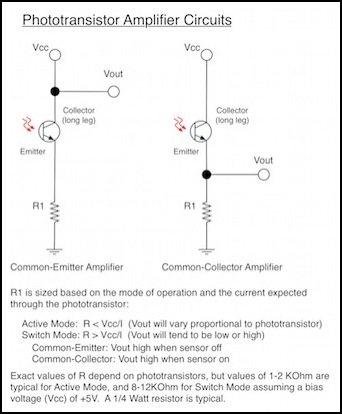
In the “Common-Emitter Amplifier” circuit, the voltage source is read above the phototransistor. If the transistor is off (not illuminated) voltage will build up, and Vout will be at or close to Vcc, meaning about +5V. When it’s on, current flows through the phototransistor, and Vout will be lower (but not zero, due to R1 and the inherent current limit of the phototransistor). R1 is there to give the current a path to ground that limits the amount of current that can flow, preventing damage. The lower resistance it has, the lower Vout will read when it’s in its “low” state.
In the “Common-Collector Amplifier” circuit, things work similarly except that the pin being read is below the transistor. Thus when the transistor is off, R1 will pull the voltage to ground. When the transistor is on, voltage will “back up” due to the resistor, and Vout will read a non-zero voltage. Again the behavior of Vout depends on the value of R1: a smaller R will yield a lower “low”.
For the phototransistors I’m using, 2 KOhms is probably a good minimum (lower than that, and too much current will flow, although since this is a transistor, not a LED, that’s not as serious a problem as in LED circuits). That’s also roughly the value needed to make the sensor work in “Active” mode, where the value read will vary proportionally with the strength of the light.
Note: the number is calculated from the typical current through the transistor, which for these is between 0.6 and 2.4 milliAmps. In practice I found improved sensitivity up to about 5K ohms. However, while I measured R1/R2 as working with 5K ohm resistors (and working slightly better than with 2K ohm ones), in truth to be sure of the circuit working at its best over all normal photodetector variation, the size of these resistors probably shouldn’t exceed 2K Ohms (R = V/I = 5V / 0.0024 A = 2,083 ohms).
This mode of operation (common-collector) counts on voltage backing up behind R1 regardless of the rate getting through the phototransistor. If the transistor is off, nothing flows and the Vout pin is pulled down to ground. If it is on at all (light is present), current flows, and the high resistance makes it harder for it to get to ground, and a voltage builds up. The more light, the more current (charge per unit of time), the higher voltage is built up.
This isn’t perfect, but with the common-collector design, the resistor can be calibrated to the level of light you want to detect, and used to craft a simple on/off control. In practical terms, that’s probably more bother than it’s worth, at least if you have the option of reading Vout with an Analog/Digital converter, which is what the Arduino’s Analog pins do, but it’s something I thought I’d want to look into. For these transistors a value of 8 KOhms or greater should be enough to make it work this way. In practice I found this unworkable, as the resistor value needed to be calibrated for ambient room lighting (incandescent lights have an IR component), and since that can vary, there was no way to do it when designing the circuit.
So, I ended up using Common-Collector (I could have used the other), and was forced into using it in Active Mode, using software to compensate for variations in room lighting.
Multiplexing Sensors
Analog pins are a limited resource on an Arduino, so it’s important to use them as efficiently as possible. While I could connect each sensor to its own pin, there’s a better way: multiplexing.
This is the basic concept: there are banks of LED/phototransistor pairs sharing an analog pin that can be used to read more than one sensor. A digital pin serves as the voltage supply: turn it on, and all of the phototransistors connected to it begin to build up charge, either above the phototransistor (if off) or between the photo transistor and the lower resistor (if on). The latter is the voltage that is read by the analog pin. The current requirements for the phototransistors are under 2.5 mA each, so you aren’t likely to run out of power, assuming the LEDs are driven from a different supply.
My test circuit replicated one set of four sensors, arranged as two banks of two sensors each, as shown below. The LEDs were driven from a separate 12V DC supply and consumed about 30 mA total. I went through several iterations of the resistor sizes before settling on these values, which seemed to produce good results.
The LEDs and sensors are the Lite-On ones mentioned at the top of the page. The LEDs are infrared LEDs (marked L1 to L4 in the diagram below). The phototransistors are infrared-sensitive, and designed to work with these LEDs. Both are lensed and have sideways oriented active areas, meaning if the pins go down to the ground, the light from the emitter will shine in a narrow beam across the tracks into the sensitive area of the phototransistor, which will turn on, allowing current through. In theory, there will be a substantial variation in output when a train passes in front of the emitter. In practice, very bright room lighting reduced the range of variation because scattered light from the room lighting was also sensed.
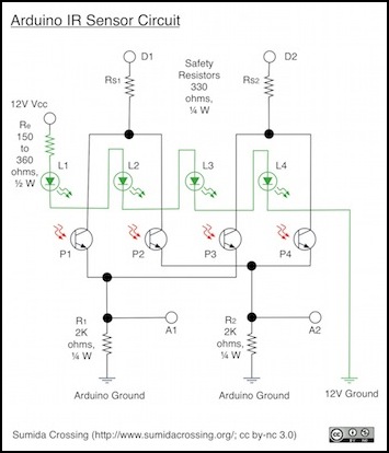
There are four resistors in the Arduino portion of the diagram, not counting the one on the LED supply. R1 and R2 are the ones needed to limit the current to ground, which were discussed above, and Rs1 and Rs1 are “safety” resistors to protect the Arduino.
Arduino pins are driven by output transistors, which can be damaged if you short them to ground. That can leave you with an Arduino with a pin that will never work again. Resistors Rs1 and Rs2 prevent that happening. A value of 330 ohms will limit current from a +5V pin to 10 mA, which is more than the transistors need to operate, but well below the 40 mA threshold where the Arduino risks damage. Because this circuit will eventually get installed on a layout, where wring errors are quite possible, these provide a safety net to prevent me from damaging the Arduino. They won’t avoid every problem, but they’re a cheap fix for a likely one.
Note: the size of Rs depends on the maximum current, which depends on the number of phototransistors and how much they draw (which varies in practice), so you need to make the resistor a size that will allow the needed current through without dropping too much voltage. As only one is read at a time, and very little current leaks through R1 or R2, once charge has built up you aren’t going to require more than 2.4 milliamps. At that current, the resistor is dropping about 0.8 volts, leaving ~4.2 (or a bit less) available for the phototransistor to switch. This will limit the maximum reading from a sensor to about 4.2/5*1023 = 859, rather than 1023, but in practice that won’t be a problem. You could make the resistors smaller, allowing a higher sensor voltage, with more current through the pin in a short, at long as you keep the value above 125 Ohms (which limits current to 40 mA). I may experiment with this to allow faster operation of the sensors, but I’ve found 330 Ohms to work well in practice.
The LEDs are always on. This means that they can’t be located where a phototransistor can “see” two LEDs, but that shouldn’t be a significant problem, as the angle of the output light is 40 degrees. I found the sensors to be very narrowly focused, and sensors an inch (25mm) apart (side to side) did not pick up significant light from an adjacent LED on the other side of an N-scale track (about 1”, or 25mm, away).
Because the LEDs are always on, this means that I don’t waste any pins controlling them, and their power can come from a separate supply and not subtract from the Arduino’s power budget.
The “multiplexed” part is that D1 being raised will cause P1 and P2 to become active. If A1 is then read, the state of P1 will be known, and if A2 is read, the state of P2 will be known. If D1 is set low, and D2 is raised, then P3 and P4 will become active, and reading A1 will report the status of P3, while reading A2 will report the status of P4. This will let me read four sensors using two Analog pins (or 8 with four).
One thing I discovered was that it was necessary to wait a short time after turning the digital pins on, before reading the analog pins. This allows charge to build up at the analog pin. The required delay is only a few tens of microseconds (I’ve used 100 microseconds to be conservative), but it makes a big difference in the readings.
This design can easily be generalized to handle more sensors. It helps to think of these as “banks” of sensors, with each bank connected to one digital pin. There can be as many banks as there are available digital pins. Each bank can contain as many sensors as there are analog pins. Each sensor could require 2.4 mA and that will add up, so there is a limit of around16 sensors per bank (and it’s safer to limit yourself to a bit less than that), and probably 40 or 80 (depending on Arduino model) total if the Arduino isn’t doing anything else. You’re likely to hit other limits (like time available to read them) first.
Reading Sensors
Actually reading the sensors requires software to switch the digital pins on and off, and to read the corresponding analog pins. And, because the real world is a messy place, simply reading a number from the sensor may not be enough. It can be, depending on your needs, but for more reliable operation you’ll need to average out several readings, through a method called “smoothing” to make the sensor numbers more reliable, and in most model railroad operations you’ll also want to avoid misreading them though a method called a “hold-down timer”. I spent some time developing software to do just that, and have packaged it up as an Arduino library.
Design Issues
When the phototransistor is exposed to light, it takes some time to turn on. This is measured in microseconds, and not many of them (10-15 per the datasheet). A “read” on the analog pin takes a relatively long time (~110 microseconds), so I didn’t think I needed to worry about that part. I was wrong, and I think the reason is the current limiting done by the safety resistor (allowing 10 mA max), plus the leakage allowed through the main resistor at the bottom of the circuit (2.4 mA). This takes time to build up a charge (voltage) to be read by the analog pin.
A photo transistor isn’t just an on/off device. It’s “partly on” with a little light, “more on” with more light, and “really on” when brightly lit. The more “on” it is, the more current it lets through, but if any is getting through it’s going to build up on the output side. And that means that even a “dark” sensor is probably getting enough infrared from room lights to cause a “false positive” when it gets read if enough time has passed. One fix for this is to read the pin twice (which obviously takes twice as long) and discard the first reading, which will be the potentially false one. I tried that, and discovered that it wasn’t really necessary. As long as I was reading the sensors fairly often (once a second) the two values were almost identical in most cases.
But the difference between high and low varied quite a bit. With room lights off, and just the LEDs, “off” was 0-20 or so (on a 0-1023 scale). On was around 600 - 800 (except for one phototransistor, which seemed to be defective, and was around 300 when “on”; I think its lens is bad and not focusing on the LED). When I bathed the test area in light from a halogen desk lamp (a worst-case incandescent-light test), “off” was around 400 - 600 and on was around 750. So I needed to make my software sophisticated enough to adapt to changing room lighting and figure out what “off” is as lighting varies (from people leaning over the layout, etc).
Finally, because this is being used in a control program, I want to be able to do other things that require fairly close timing (on the order of a millisecond) while also working with the sensors, so I can’t just read every sensor in one pass. The program needs to allow reading things on a more granular level, to give me time to do other things. As long as I keep the number of sensors in a bank small, this is relatively easy to do since I can just read one bank, go do other things, then come back and read the other. If I wanted to break banks up into subsections, it would get a lot more complicated, but I don’t need to do that for the quantity of sensors I’m going to be working with.
Sensor Smoothing and Adaptation
Smoothing is a complex enough topic that I have a whole page dedicated to discussing it in detail, so I’ll just summarize the important parts here. The basic idea of smoothing is that any new reading is averaged with past readings, through a technique known as an “Exponential Moving Average”. This causes big changes to take effect slowly, and if the big change doesn’t last, it mostly gets ignored. Thus if some electrical noise caused a sensor to go from 200 to 400 for a millisecond or two, then fall back, the sensor reading might go from 200 to 250, but it wouldn’t change any more than that, avoiding a “false positive” report that some real-world event had happened.
A potential downside is that the program won’t “see” real changes immediately, but if you’re reading the sensor every few milliseconds that doesn’t really matter. An N-scale bullet train moving at 300 scale kph (186 mph) is moving about half a meter (18”) per second, but that works out to half a millimeter per microsecond. You can take tens of milliseconds to detect that the front has arrived, before even the tail end of the first car has moved past the sensor. I’m using a smoothing algorithm that will allow changes to be detected after about 3 read cycles, so if I read these every three milliseconds (which is reasonable) then the train has moved at most 9mm (~3/8”) before I detect it. And most trains move a lot slower than bullet trains.
Smoothing avoids problems caused by sudden changes. For example, a bit of electrical noise on the wire, or a flash from a camera. Electrical noise is likely injected from AC sources, and the slowest of these is probably going to be wall current, at 50 or 60 Hz depending on where you live. This causes a rise and fall over about 8 or 10 milliseconds, so if you wait 8 milliseconds to react, the change is gone. If you were to wait only four, the change might be detected (depending on how synchronized your reads were with the cycle). This means I should read a specific sensor no more often than once every 2.7 milliseconds if I’m using a 3-sample smoothing approach. Camera flash is much less of a problem. The longest lasts about 1/500-second, or 2 milliseconds, so if I read even once a millisecond, the change is gone before it can be reported.
Another, and likely more serious source of electrical noise is the solenoid-based turnout. When one of these is thrown, voltage goes from zero to a high of 12-16 volts very quickly, and this can induce a current spike in nearby wires. It will be shortlived, as the voltage applied to the solenoid is DC, and only a changing voltage can induce a current. Although sensors are often located near turnouts, it’s a good idea to try to keep the wires run separately, and cross at right angles where necessary. But there is likely to be some induced noise when a turnout is thrown, and smoothing can minimize the impact of that.
There can be longer-scale changes: a person leaning over the layout, or a door opening slowly that lets more light in. Most of these will be relatively distant, and thus affect multiple sensors, so having the room reach to changes in room lighting over a longer scale can adapt the sensors to these. My light adaption uses a smoothing algorithm that takes 11 cycles to reach the half-way point (at 3 msec reads that’s 33 msec to get halfway). Most human motion happens on a scale of a few millimeters per millisecond (or meters per second), so things with human causes will probably be smoothed out by this (trying to make the smoothing take longer for slow-moving changes may ignore problems it needs to react to). If this ends up ignoring things it shouldn’t, I can switch to one that adapts twice as fast, but that may react too quickly.
Software Design
The software to read the sensors wasn’t trivial. This is analog circuitry, even though I’m using it to get a digital result. And Analog is messy. The software needs to deal with that. When the phototransistor is exposed to light, it takes some time to turn on. This is measured in microseconds, and not many of them (10-15 per the datasheet). A “read” on the analog pin takes a relatively long time (~110 microseconds), so I didn’t think I needed to worry about that part. I was wrong, and I’ll get to that in the description of the tests below.
A photo transistor isn’t just an on/off device. It’s “partly on” with a little light, “more on” with more light, and “really on” when brightly lit. The more “on” it is, the more current it lets through, but if any is getting through it’s going to build up on the output side. And that means that even a “dark” sensor is probably getting enough infrared from room lights to cause a “false positive” when it gets read if enough time has passed. One fix for this is to read the pin twice (which obviously takes twice as long) and discard the first reading, which will be the potentially false one. I tried that, and discovered that it wasn’t really necessary. As long as I was reading the sensors fairly often (once a second) the two values were almost identical in most cases.
But the difference between high and low varied quite a bit. With room lights off, and just the LEDs, “off” was 0-20 or so (on a 0-1023 scale). On was around 600 - 800 (except for one phototransistor, which seemed to be defective, and was around 300 when “on”; I think its lens is bad and not focusing on the LED). When I bathed the test area in light from a halogen desk lamp (a worst-case incandescent-light test), “off” was around 400 - 600 and on was around 750. So I’m going to need to make my software sophisticated enough to adapt to changing room lighting and figure out what “off” is as lighting varies (from people leaning over the layout, etc).
