


LED Lighting Power Wiring
The layout has a 12V power bus for building and other lighting. I’ve changed the design for this several times now. Originally there were to be two (or more) using 1.5A power supplies. Then I decided to use a couple of spare outputs on the PS2012 (since I was using less of that system than I’d originally planned). Now I’m back to the 1.5A (actually 1.6A but I’m fusing them for 1.5) supplies since I decided I wanted a stable 12V supply (the PS2012 puts out closer to 14V). This may mean I’ll need to add more, or switch to larger regulated supplies in the future, but I’ll set that potential problem aside for now.
Lighting Power Bus
The power bus consists of 18ga wire color-coded Yellow/Orange (Yellow is positive; I always use the lighter color for positive to avoid confusion). I could have used smaller wire (on-table wiring is 22ga or even smaller, due to the low amperages handled), but this wire is heavy enough that hitting it accidentally when working under the layout isn’t likely to break it. The power supply is connected to a fuse box, and on my main power panel, there is a switch in the positive leg of the bus.
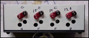
Fuse Box
My power supplies are regulated “wall wart” transformers. These have a standard 2.1mm plug on the end of the wire. To connect this to the layout, I built a simple fuse box. This has a 2.1mm jack on one side, with a fuse holder, and a pair of screw terminals on the other. The positive leg from the jack goes through the fuse to the red terminal, and the negative leg goes straight across to the black terminal. I’d built a small version of this originally, but when I added several other power supplies of the same type for 12V and 15V accessories, I decided to make one large fuse box, shown below before I added the lighting circuits. The fuse box and power supplies are described more fully on the DC Power Supplies page.
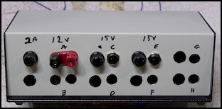
Fuse box (before lighting circuits added)
Main Power Panel
From the fuse box, power is routed through the main power panel, where each of the two lighting circuits has an ammeter and switch (lower right corner of photo below). This lets me turn the lighting off if I don’t want the lights on while running trains for some reason. There is also an ammeter, so I can see just how much power I’m using, so I’ll know when I’ll need a larger supply or an additional lighting bus.
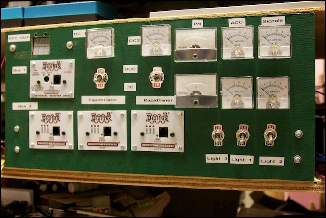
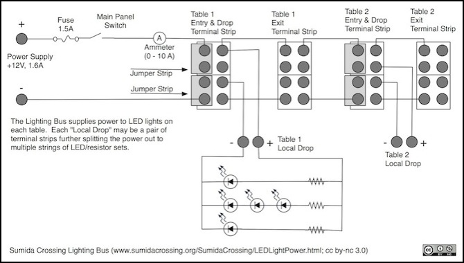
Table Wiring
The power bus is wired through the tables using two four-position terminal strips per table, one at each end, jumpered to the next table in the series. From one of the two strips, a pair of wires drop to a local distribution pair of terminal strips. From these, wires run to different above-table lines that have LED/resistor sets connected across them.
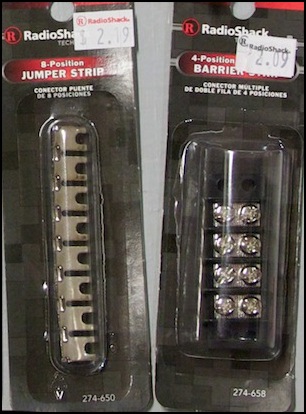
Jumper Strip and Terminal (Barrier) Strip
The terminal strips I’m using are Radio Shack ones (they call them Barrier Strips; RS 274-658 for the 4-position ones I’m using). These use #6 screws, as opposed to the larger ones I normally use that have #8 screws. The reason for using these is that RS sells a Jumper Strip (RS 274-650) which is very handy for bridging multiple terminals on a strip together. The jumper strips can be cut to the number of segments needed using heavy-duty wire cutters. I used these on my old layout for feeder wiring, and they worked very well.
Reverse Current Testing
At one point I considered using a diode on each drop strip to ensure that even if the power supply is reversed, no reverse voltage will get through to the LEDs (note that this won’t help if you hook up the LEDs themselves backwards). I’d planned to use RS 276-1141 Epoxy Rectifier Diodes. These are large, and rated for 3A, which is likely much more than I’d ever use on one table. RS actually sells several similar ones in the 276-114x line; these have the smallest surge rating, and are thus the cheapest, but any of the others could be used.
I did some testing with this to see how it worked. The diode has one bad side effect which I knew: it uses power, and thus drops the supply voltage. My 12V supply actually becomes 11.3V at the LED/resistor set. The effect of this is minor: I can calculate my resistor values assuming 12V just in case I ever decide to remove these, and the LEDs will run a very small amount dimmer.
Still, in the end I decided that I could wire up my supplies reliably (thanks to the fuse boxes I’d built) so accidental reversal was very unlikely, and I decided to omit the diodes.
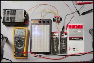
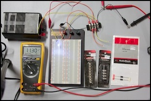
Power Test: 11.96VDC from power supply (left), 11.30VDC to LED with diode (right)
