


Testing the Arduino Tram Controller
After a long time set aside (about two years) I returned to this project in April of 2013, and began actually programming the Arduino and testing it.
The first thing I did was cut the Vin pin on the Ardumoto shield, to disconnect the motor power supply from the Arduino power supply. For testing, I have a large 12V, 2A DC supply I can connect to the Ardumoto, and the Arduino will be connected to my computer by USB, and powered from that. Note that only the Vin pin needs to be cut, the ground pins remain connected. In the production version, I’ll attach two 600 mA regulated 12V supplies, one to the Arduino, and one to the Ardumoto.
As a test bed, I set up a short length of straight Unitrack, and connected it to the Motor A output (screw terminals labelled “A”, pins 1 & 2, on the four-screw blue header). I then connected my power supply to the smaller blue terminal, pins marked “+” and “-“. Lesson 1: the polarity matters. I had + and - reversed at first, and it didn’t work at all. Looking at the schematic shows why: there are diodes on the board to prevent reversed wiring (this is probably to protect the chip). On the track went my bargain-table N-scale B23 locomotive, which I don’t care if I somehow manage to fry while doing testing.
That fixed, I loaded up a test program that would run the motor at 32/256 voltage for two seconds, stop for one second, reverse direction, and repeat. This didn’t work, although I could tell I was getting voltage on the track; my loco just sat there. However, while the voltage was on, it “sang” with an odd ringing sound. I hooked up my scope, and discovered that the PWM being generated by the Ardumoto was at about 500 Hz (I measured 489 Hz), which it turns out is the default for an Arduino’s PWM. And my loco was just sitting because apparently the voltage was too low. I found out later it had to be well above 50% to move at all.
PWM and The Arduino
I really don’t want to use 500 Hz PWM anyway. It’s a fine frequency for light-intensity controls, but a poor choice for a motor controller (unless you need to maximize torque). I want 16 kHz or more, called “supersonic” in the Model Railroading trade. Can I do that? Apparently I can. The reason is that the Ardumoto simply controls the output to the motor by turning it on or off and reversing polarity. The Arduino is the source of the PWM signal, and this can be controlled by the program running on it. It does, however, require more than the usual amount of mucking about in programming code (any time you need to mask and shift bits, you know you’re in the deep end).
There is some decent documentation of how Arduino PWM works on their site. Well, decent in that it provides a useful background for understanding other material. It might have been sufficient if all I needed was to make an Uno work. But the Mega is a bit “special”, and actually making sense of it requires more background knowledge than I started with. Part of the problem is that PWM functionality changes depending on the specific processor used in the Arduino, and the explanation isn’t applicable to the Mega 2560 I have. The terminology is also confusing, and I spent considerable time setting bits in the wrong registers as a result.
Basically, the standard Arduino processor used in most models, including the Uno I will eventually use under the layout, uses Timer2 to control the two PWM pins used by the Ardumoto, but the Mega 2560 uses Timer3 for motor A (pin 3) and Timer1 for Motor B (pin 11), and these are a bit different from Timer2.
The good news is that on a 16 MHz Arduino, which both are, the timer can be set to produce a 32 kHz PWM (the next lower value is 8 kHz). It’s actually possible to do more than this, but this is the “simple” form that doesn’t require me to write and debug interrupt handlers and understand the minutia of PWM generation.
What it comes down to is setting a number used to divide a clock derived from the CPU clock frequency. This defaults to “divide by 64”, which produces a 489 Hz PWM signal when used in Phase-Correct PWM, and I want a divisor of 1, which will produce 31 kHz. There’s no easy way to generate 16 kHz, although I could get 8 kHz by switching to Fast PWM mode, which would work for this application (phase-correct is mainly needed when multiple motors need to be synchronized, such as when driving a robot).
Test Program
I started with the example program that Sparkfun provides, just to make sure the Ardumoto was working, and as noted above it was. Then I started modifying this. First I added some code to allow messages to be sent to my computer (using the Serial Monitor) in the Arduino development environment. This lets me print things out so I know where in the program it is, to help catch “why did it go there?” programming mistakes, and well as for printing out the contents of variables when I’m trying to sort through a problem (it’s low tech, but this is all I need, and it seems most Arduino debugging is done this way; rather primitive for the 21st century, but it is a simple embedded processor rather than a full-size computer).
And with that, I started working on getting the PWM frequency changed, using my simple test program that would run a train back and forth based on a timer, without any sensor use. This would prove that I could configure the PWM correctly, and that I knew how to change throttle and direction. Actually, I proved both of those in the original demo test program, then they stopped working for a bit when I was playing with PWM. Then I got very confused.
Finally, in a fit of desperation, I read the manual. Or rather, I stopped trying to find someone who had done it and provided a clear explanation online, and I read the description of the PWM control registers in the AT Mega datasheet (the name is a bit of a misnomer: this “sheet” is 447 pages long) and I started reading through the Arduino development environment source files to see what commands like analogWrite were really doing. The nice thing about open source is being able to read the source code. The bad thing about open source, is being able to read the source code, so nobody’s really motivated to write good documentation.
And with that, it began to make sense. I now know how to get 31 kHz PWM on my Mega (and I think I know how to do it on other common models, although that could use more testing), see the parent page for a downloadable of my original program’s source.
After I had the basic ideas down, I took those and wrote a library of functions to control a pair of motors using any of several common motor shields on any of several common types of Arduino, discovering along the way that some combinations were incompatible. The problem is that some of them end up with the shields PWM input on an Arduino pin that’s connected to Timer0. In the Arduino, Timer0 is used for time functions like delay(), and can’t be modified to produce different-frequency PWM without breaking time-based functions. As I need timing for a number of things, and expect others will too, I disabled those combinations of Arduino and shield in the library. The library code is (soon to be) online, see the Tram Controller page for a link.
Output Filtering
The output of a PWM motor controller is a square wave. Square waves and inductors (like the coils in the motor) don’t really get along all that well. The use of supersonic PWM helps to an extent, but at low duty cycles (low average voltages) there’s still a considerable mismatch. So I’d wondered if there was anything I could do to smooth out that waveform, thinking vaguely about a using a capacitor somehow. My hope was that this would allow the train to move at lower duty cycles, providing a smoother overall response. It would need to not store power too long, since I want the motor to stop or change speed responsively when the throttle is adjusted. But if it could average out the square wave somewhat, that would be an advantage. Googling about, I found contradictory advice from “it won’t work” to “it’s terribly inefficient” to “you must do it” (which, of course, I know is untrue).
But among the noise, I found someone who’d done just that with an Arduino, using what is essentially a low-pass filter, and they even had a link to a calculator for working out suitable sizes (although I found it more useful to check the results of my own work than to discover the values I needed). After deciding I needed a resistor around 5 ohms and a 100 microfarad (100 MFD).
I chose those values to minimize loss in the resistor, and because that was the largest capacitor I could easily find. With a typical N-scale loco using less than 300 mA (often much less), that means a worst-cast voltage loss of 1.5V (and typically under 0.5V) and a power requirement of just under a half-watt (P = VxA = 1.5V x 0.3 A = 0.45 mA). The capacitor is a ceramic one, rated for 100V operation (my goal was 50V or better, but this is what the store had). If you want to create your own, the important aspect is what current will flow through the resistor. My numbers are for typical modern N-scale (and match the 300 mA / output power budget of the motor shields I’m using). From that I calculate the loss in the resistor using V=IR (V = 0.3 x 5 = 1.5V) and then the power lost in the resistor using P=VA as above to get the size (wattage) needed. For the capacitor, you need one that isn’t polarized, meaning it doesn’t have + and - leads (i.e., not a typical cylindrical “electrolytic” capacity, which are all polarized). And for voltage, a good rule of thumb is 4x the operating voltage, because PWM and an inductive load can generate spikes up to 2x the voltage, and it’s always a good idea to have a 2x safety margin (so for 12V, I could have 24V spikes, and a 2x margin gives me 48V). Marking the capacitor large will reduce ripple, but extend the time it takes to charge up and power down.
Reality Intrudes
Unfortunately, 100 MFD capacitors don’t exactly come cheap, running around $50 each in a 50V model (with 12V power, I can have spikes up to 2x that with an inductive load, so I really need a capacitor to be twice that large, or 48V, to be safe). The other thing to worry about is the capacitor’s tolerance for “ripple”, the amount of variation in the voltage. With a 100 MFD capacitor at 31 kHz, ripple was a fraction of a volt. But with smaller capacitors it became quite large (0.6V at 33 MFD, 1.9V at 10 MFD). Unfortunately, ceramic capacitors are less tolerant to ripple at lower sizes (at least the ones I found), and the smallest one I could use (assuming 31 kHz; things got worse at lower frequencies) was 33 MFD.
In the end, the best one I could find was a 47 MFD, 50V, model (Digikey 565-3276-ND) at US$26.65 each, which was designed for “Smoothing circuit of switching mode AC-DC or DC-DC converter”. I also found some surface-mount tantalum capacitors (718-1408-6-ND) at US$15.80 each. But while cheaper, the extra work of dealing with surface-mount components put me off (they also appeared to be polarized, which didn’t seem like a good idea). So, while I can do this, it’s a substantial hit on the budget, and at this point it’s unclear if it will have any real effect on the operation of a train. Still, I’m interested enough that I’m going to give it a try. First, however, I did do some modeling of the circuit to see how it “ought to” behave.
This turned out to be overthinking the problem. Don pointed out that I could use a polarized electrolytic capacitor between each motor line and ground. I can do that, because at the output of the Arduino I still have access to the power supply ground. This isn’t like a DCC decoder on a train, where it has no way to connect to a ground line. That would simplify this considerably. I had become involved in working on sensors by then, so I haven’t yet come back to this. As it turns out, the train runs pretty well at 32 kHz without this.
Circuit Models
As mentioned above, I used the Low-Pass Filter calculator to do some modeling of how this would work given the values I planned to use for the resistor and capacitor, and various PWM frequencies. The charts below show how these work at 20% duty cycle (about 2.4V, which ought to be enough to make the loco move, but probably not quickly).
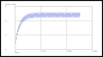
Here are the original graphs for the 100 MFD capacitor:
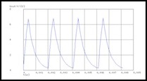
Theoretical behavior of 5 ohm, 100 microfarad RC network on 489 Hz, 8 kHz and 31 kHz PWM at 20%
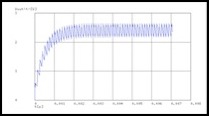
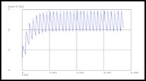
And here are ones for 33 MFD at 8 kHz and 31 kHz (it was useless at 489 Hz and I didn’t bother graphing it).
Theoretical behavior of 5 ohm, 33 microfarad RC network on 8 kHz and 31 kHz PWM at 20%
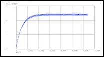
And finally for the 47 microfarad one I decided to use:
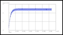
Theoretical behavior of 5 ohm, 47 microfarad RC network on 8 kHz and 31 kHz PWM at 20%
At the normal Arduino PWM frequency, even 100 MFD is not doing a whole lot of good. Ripple (the range of the voltage swings) is 9.2V, and I doubt I could find a capacitor that would tolerate that even if I wanted to use it. At 8 kHz ripple is down to 0.75V. And at the 31 kHz I plan to use, ripple is just 0.2V. It’s also taking just over a millisecond to get to 90% of the final average voltage, which means it’s not going to significantly affect the responsiveness of the locomotive to the throttle.
With the 33 MFD capacitor, ripple at 8 kHz is 2.2V, which is pretty poor . However, at 31 kHz (which is what I actually plan to use) it’s much better, with ripple down to 0.6V. With the 47 MFD capacitor I finally settled on, ripple at even 8 kHz would be just 1.6V, which is well inside its 3.0V tolerance range, and at 31 kHz ripple is down to 0.4V, and the time to 90% is actually below a millisecond (the smaller capacitor stores less power).
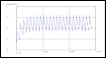
Just to get a second opinion, I simulated it with the Java-based circuit simulator Don had pointed out a couple of months previously, at falstad.com, and it showed similar behavior (I can’t get the link to the simulation to export with my browser/Java software for some reason, so all I have are the pictures below). This certainly seems to show the same behavior with a locomotive motor in the circuit (the coil and right resistor simulate the properties of a motor).
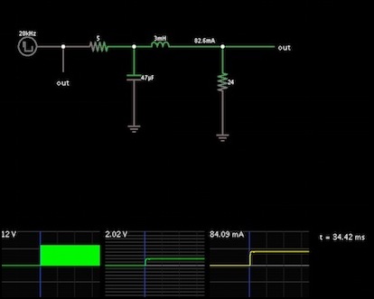
Circuit for Kato loco motor on filtered output (20 kHz, 20% duty cycle)
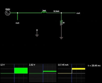
Circuit for Kato loco motor on unfiltered PWM output (unfiltered, 20 kHz, 20% duty cycle)
As you can see from the thickness of the lines in the two right-hand graphs (which measure the circuit at the “out” label) without the filtering, there is considerable ripple around the centerline without filtering, and very little with it. Now to test it: does it make a difference?
I set this aside to think about it, during which time Don noted the alternate approach described above. And on thinking about it, I realized that this was what I’d actually simulated here: a polarized capacitor connected to ground.
More Testing
After writing up my motor control code as a library, and creating a simple program that worked as a DC Power Pack using a potentiometer as a throttle knob, I began to test with an actual running train. This used my bargain-table B23 loco as a test subject, to avoid damaging a valuable model if something went wrong. To my surprise, nothing did.
What I found was that there was about a 15% reduction in top speed with 12V PWM as compared to 12V DC from my Kato pack (the Kato will produce up to 14.4V DC, so the actual speed difference is larger).
That concluded the testing and I finished up the library and published it (see the software section at the bottom of the main Tram Controller page). Once I put all the different software and hardware bits together to make the main program I’ll need to do some more testing to ensure I did that right, but I may not bother to report that here. What matters is that I’ve determined how to do what I believe I need to do to make a good DC motor controller for small model trains.
