


Automatic Block Signals and Centralized Traffic Control
Originally, railroads had individuals at each place where trains could move between different tracks, variously called operators, signalmen, levermen or towermen. These individuals were responsible for controlling the motion of trains by setting track switches (or “turnouts”, both terms are used on prototype railroads) and signals. The locations where they worked had a variety of names (signal boxes, towers, cabins, etc) but were also known as interlockings because the switches and signals there were interlocked to prevent the operator from allowing a movement that could permit two trains to run into each other. Originally all of these controls, including the interlocking, were entirely mechanical. But in the late 19th century, electric systems began to be used. Although, as with most things on the railroads, mechanical interlocking systems remained in use for a very long time, and likely are still in use in some places today.
Early electric interlockings still required a local operator, who could only exert control over switches and signals relatively close by, usually within visual distance (one reason signal towers were often placed fairly high, to provide better viewing). There were centralized control systems before CTC, usually in large stations (Grand Central Terminal in NYC was an example). But it was CTC that really broadened the scope of centralized control.
In 1927 Centralized Traffic Control, more commonly known as CTC, was introduced by the General Railway Signal company in the U.S. (now incorporated into Alstom Signaling) under the name G. R. S. Dispatching System (centralized control was what it did, not its name, although the well-known name came quickly into use). CTC allowed one person, typically called the dispatcher in the U.S., to control multiple interlockings remotely. That first 1927 system put one operator in control of 40 miles (64 km) of mainline.
Once introduced, CTC spread rapidly around the world. GRS had associated companies in London, Paris and Melbourne. Japan installed its first CTC system in 1937, and over time it was widely deployed there. Later systems layered further control above using computers. The Program Route Control (PRC), developed for the introduction of the Tokaido Shinkansen in 1964, uses computers to control CTC route setting. Collectively CTC and PRC are called Traffic Route Control (in Japan) and remain in use up to the present day, as part of a larger and more complex system.
Although Union Switch and Signal Company (today part of Ansaldo STS USA) may be a better-known manufacturer of CTC systems, as noted above they didn’t develop the original technology. Sedgwick N. Wight of GRS is credited as the inventor, but per his own writing it was developed by a number of engineers at GRS working closely with railroad Operating staff. US&S was an early promotor of the system, however, and was responsible for many installations. Both companies added new innovations to the technology over the next few decades, such as entry-exit (NX) route selection (GRS) and code-based signaling (US&S).
CTC was successful because it increased the effective capacity of lines by allowing trains to follow each other or pass each other smoothly, without one having to stop and wait for the other. It also provided one person with an overall view of activity across a wide area and allowed them to anticipate problems and plan ahead. Initially it was only used where track capacity was a limiting factor, because installing a CTC system was very expensive, but cheaper than building a second (or third) track. I’ve seen estimates that the cost of a CTC system was around $10,000 per mile (in 1930’s dollars). At that time, adding a parallel track cost approximately $50,000 per mile, so the savings were considerable (the numbers do come from a manufacturer, so they could be “optimistic”). Over time CTC was applied in additional places because it also reduced costs by reducing the number of operators required.
CTC originally used a large panel with display lights, controls, warning bells, and lots of relays. This was known as the CTC Machine. But a CTC machine didn’t directly control the remote switches and signals. It simply passed along the operators commands to relays at the interlocking, and the logic regarding which commands could and couldn’t be acted on safely was local to the interlockings. Today CTC “machines” are often software running on computers, and the interlocking systems they communicate with may be computerized as well (or not), but they often function very similarly to those of 1927.
Another innovation of CTC machines was that they produced a written record of train movements, using a number of pens that marked block occupation changes on a slowly-advancing roll of paper, which was also annotated and signed off by the operator. This provided a permanent record of trains being on time (or not) and of the CTC operator’s authorization of movements, which was useful for both routine management of the railroad, and investigation of accidents (performing much the same function as a modern airplane “black box”).
For detailed information on the operation of a CTC system, see here, and here.
Signals
Under a CTC system there are two primary divisions of signals: those that control access into an interlocking (“home” signals) and those that pass trains along a line between interlockings (“block” signals). Although these two systems work together, they are operated differently. In some systems, there may be additional signals: “distant” signals providing advance notice before arriving at an interlocking, and “starting” signals on the outbound side of an interlocking to control departure, but these do not occur in all variants. Japanese signaling uses all four kinds, but not necessarily on every line or at every interlocking.
Automatic Signaling
CTC normally only controls signals at an interlocking. When lines between interlockings are more than a few miles long, it is worthwhile to break them up into blocks, with signals controlling access into each block. Normally “automatic” signals, which existed well before CTC, are used between blocks. Automatic signals work entirely off inputs from train detection systems and turnout (track switch) position indications. Automatic signals can thus work entirely without human supervision. But some more complex systems add a degree of manual oversight to automatic signals.
The Automatic Block Signaling system (ABS) was, and is, one method used to control signals on lines between interlockings, but there are many variations on automatic signaling, with different names in different countries. Even the name ABS is sometimes used for the specific form that is entirely automated, and more generally to mean any system which has automated signals at its heart.
In the simplest form, signals will be “Clear” (green) in both directions until a train enters one end of the line, at which time all opposing signals will “tumble down” to red. This method can be problematic, and lacks any option for an operator to favor one train over another without additional “starting” signals at each end under manual control.
A variation is Absolute Permissive Block (APB) control, which uses automated signals that are at “Stop” (red) until an operator at one end (or at a CTC machine) sets a “direction of travel”, at which point signals along the line all the way to the next interlocking change to “Clear” (green) in that direction. This allows the operator to determine which train can use the line between two interlockings first if there are trains at both ends, using the home signal of the interlocking to permit a train into the interlocking once a route has been set that will take it to the cleared line.
As a train passes signals, they revert to “clear”, going through intermediate states such as “caution” (yellow) as the leading train passes through additional blocks. This allows trains to follow each other relatively closely until the operator clears the direction of travel. In some systems an “overlap” is used, such that a train must pass a certain distance beyond the next signal before the previous one goes yellow. This increases the following distance, but can improve safety when short blocks are in use.
Under CTC, signals between interlockings are termed “intermediate” signals, and in a broad sense they work like ABS signals. Most likely they are the APB form, where the operator controls the direction of traffic.
When the operator clears a direction of travel, this may not take effect immediately. Trains within the section of track between interlockings need to reach the far end before the direction can be changed.
Signals in an ABS system may be simple green/red ones, but more commonly will be green/yellow/red to allow slowing following trains, and they could have more complex aspects. When three-aspect (red, yellow and green) signals are used, conditions in the two blocks beyond the signal are of interest. But there are also systems that look one block further, and use an additional aspect. Where yellow (“caution”) might mean “reduce speed to medium and prepare to stop at the next signal” in a speed-signaling system, the additional indication would be “reduce speed to medium by the next signal”.
This kind of signaling is important when blocks need to be shorter than the braking distance of a train, to allow trains to be more closely spaced. Thus this is more commonly found on high-volume tracks with short blocks than on widely-spaced rural track blocks.
But regardless of type, the logic that prevents a signal from allowing a train to move into danger is always in use. Signals will be forced to “Stop” (red) if the block they protect is occupied, Further, the system must be aware of the position of any track switches (e.g., into sidings) and force the signal to a more restrictive aspect if the switch is thrown to divert a train (e.g. a “Caution” indication due to speed restrictions over a diverging switch), or simply to “Stop” (red) for trains coming from the other direction. Finally, although blocks are normally laid out to be long enough to stop a train within one block, in some cases there are reasons to make them smaller, and thus more complex signal aspects must be used to slow the train in the first block, and stop it in the second.
Other inputs than track relays may be in use to set signals to “Stop”. Examples include slide fences in mountain territory that can detect rockfalls or mudslides onto track, high-water sensors in flood-prone areas, and fire sensors on wooden bridges and trestles. In signaled territory, all of these work like occupancy detectors in that they detect a condition that would be dangerous for an approaching train, and cause the protecting signal to go red (and further ones to take on appropriate aspects such as Caution).
All of the logic controlling how signals are set is performed by what are called “vital relays”, located in cabinets near the signals and communicating with the relays of distant signals over wires. The factors that go into the decision-making for an individual signal will have been planned in advance, and the type of relays and how they are connected chosen to reflect that plan. This is a very simple system, and remains largely unchanged even today. Some railroads are replacing relays with computers, and wire with computer networks, but this is relatively recent and relays remain in use. But even with computers and computer networks, the decisions still turn largely on track occupation and the position of switches.
Blocks in an ABS system may still report their status to the CTC machines at each end, even if they aren’t part of the interlocking or managed in any way.
Japanese Use of ABS
Japanese ABS also includes a “semi-automatic block” where the presence of a train within the block is “remembered” by the signaling system, even if the train is not presently in a location where it can be detected (e.g., a freight switching a non-sensed siding). This is in addition to all the other functions of a normal ABS system.
According to a 1999 article in Japan Railway and Transport Review (“Signaling Systems for Safe Railway Transport”, see references at end of the main Signaling page), “All double-tracked sections in Japan use the automatic block system.” At it’s simplest, two signal “aspects” may be used: a green light meaning “clear” (proceed at authorized speed) or a red light meaning “stop”. More commonly a yellow light, meaning “caution” or “proceed at less than full speed” is included (and a two-light signal may have only yellow and red lights where full speed is not an option, such as at a station platform or siding). There are other indications, as described below, but these three are the most common.
On high-traffic lines the “Reduced Speed” (yellow over green) and “Restricted Speed” (yellow over yellow) aspects may additionally be used to allow more degrees of warning beyond a “Caution” signal. This would be advantageous with short blocks in urban areas as it is looking four blocks ahead instead of two. But it may not be widely used since it requires a four- or five-light signal head, and these do not appear to be common. The Sōbu Main Line in urban Tōkyō uses four-aspect signals, so it can display one of these indications, see the Tōkyō Area Signal Use page for more information.
Signals controlled by Japanese Automatic Block systems are identified by number plates on the signal mast. These are usually sequentially numbered along a line (this may only be true when ATOS is used). Depending on the railroad, this does not necessarily indicate a permissive signal (one that can be passed after stopping if it is red), as it does in the U.S. Japanese rules do allow for that interpretation, however it is falling out of favor due to some serious accidents related to its use, and some lines now treat automatic signals as absolute (trains must stop if the signal is red and not proceed until a more favorable aspect is displayed).
Interlockings
An interlocking is any place where a signaled switch is located. It can be as small as one end of a siding, or as complex as a major train station with dozens of switches. An interlocking has signals facing in each direction at its edges; there won’t be outward-facing signals on outward only lines, if lines are not signaled for bi-directional use. The area between the signals will have a track circuit to detect trains within the interlocking’s bounds (it could have more than one). The CTC system would also be aware of the track blocks on either side of the interlocking, and report their occupancy to the operator. Track blocks known to a CTC system are known as “OS sections” (where OS stands for “on sheet”, meaning that its use was part of the report generated by the CTC machine). Track blocks between but not adjacent to an interlocking (i.e., blocks entirely within an automatic block system) would not be OS sections unless they were also displayed on the CTC machine for some reason.
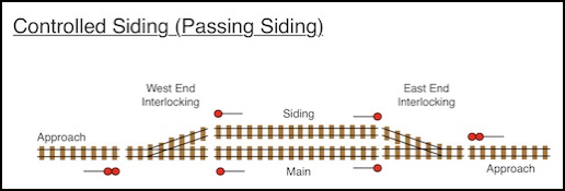
A passing siding with an interlocking on each end
Interlocking Signal Aspects
Unlike the blocks between them, interlocking use “controlled” signals, meaning that the CTC operator has control over the signal. But a CTC operator can’t make a signal green. Their only control is to make it “Stop” or “not Stop” (usually called “clearing” the signal, or making it “clear”, which does not mean giving it a “Clear” aspect). The actual aspect displayed by the signal uses much the same logic as in ABS, so it will take into account conditions in the block to which the signal gives access (i.e., the interlocking for a Home signal), as well as the block or blocks beyond it. Signals are also set based on the routes selected and the limitations imposed by the switches. Some switches restrict trains on diverging routes to slow speed, others to medium or limited speed. And, of course, signal aspects are defined by the railroad and depend on the kinds of signals in use (color-light, position, etc) and the method of signaling (speed signaling or route signaling).
The signal aspect will also be interlocked by local circuitry, so for example a signal can’t be set to an aspect other than “Stop” if there is a switch beyond it set such that there is nowhere for a train to go, or if that track leads to an ABS block that has a direction of travel set against the signal, or if the opposing signal is already “cleared”. If a signal is cleared,the actual aspect will again depend on track conditions and routing. And if a cleared signal is returned to “Stop”, it may not change immediately, and changes to other signals will remain interlocked for some period after it changes, just in case trains were already in motion and might enter the now-protected block. The CTC machine also displays to an operator if a signal has actually cleared or gone to “Stop” (it does not normally report the specific aspect displayed by the signal, although that may be a feature of more modern systems).
There is one time when the function of the interlocking can be overridden by the CTC machine, and that’s where a “call on” button is used. This can force a signal that would otherwise display “Stop” to instead display a “Restricting” aspect, which allows a train to pass the signal at a restricted speed, as long as the Engineer is looking out for anything on the track. A typical use is to allow a train into an occupied siding. Japan uses “call on” signals in a similar manner, but these use a separate marker light rather than a “restricting” aspect. They may be controlled the same way from the CTC machine.
Interlocking Switch Control
An interlocking also controls the position of track switches. These are under the control of the operator, but again are interlocked by local vital relays to prevent their being set in a manner that would create an unsafe condition. A switch can’t be thrown if a signal is set that would permit a train to travel over the switch. Instead the signal must be returned to “Stop” (which will force the next outbound signal to “Caution”) and a timer must expire with no trains detected in the block approaching the switch. Only then, when it is certain that it is safe to throw the switch, will the track switch actually change position and the indicator light on the CTC panel reflect that change.
Manual switches in controlled CTC territory will have sensors to detect when they are thrown, and locks with timers to prevent them being thrown until sufficient time has passed after limiting conditions were removed.
References
For sources used here, see the References section at the end of the parent Signaling page, in particular the MLIT Technical Standard document and various technical documents on CTC and related signals.
