


Plans for an Arduino-based Tram Controller
Work on the Riverside Station scene electronics continues; I’ll have more to say on that another time as I’m re-thinking part of my block-occupancy detection plans.
But meanwhile, I’ll mention one of my other projects: the control system for the Tram line of the Urban Station scene. Now this is a simple, short, out-and-back line, which exists mainly to give me an excuse to buy some of the Tōkyū Setagaya line light-rail vehicles (see the Tram section of my Roster) and to experiment with Tomix’s mini-rail Finetrack. So far I’ve run this manually, with a Kato powerpack. But I want to automate it, since the trams are just supposed to be background activity to make the station look busier, as I concentrate on running my commuter and express EMUs and freight trains.
The problem I had was that I wanted to replicate a two-track line with unidirectional running, and a single track station at each end that let the trains switch between the two tracks, and I wanted to do this with more than one tram running at a time. The track I’m using has slip switches, which allow a train to run through them even with the switch set against it. This lets me leave the switch in one position, and have a train enter the end station from one track and leave on the other, without any switch-control needed.
So if I were only running one train, a simple out-and-back controller with a couple of end-of-line sensors would work, and those are easy to come by. But to do this with two is a problem, as two separate power supplies are needed, and the stations need to switch between them. There are some fancy automated train controllers out there, but I couldn’t find one that could do this. And while DCC, block occupancy detectors, and a computer could solve this problem, that’s a bit like swatting flies with dynamite. And I don’t want to install DCC decoders in the trams anyway, I just want to use ordinary DC power and not modify the trams used.
What I want is really simple, and if I were more electrically skilled, I could probably knock up a simple transistor-based circuit that encoded all the logic I needed in hardware, and used a couple of old DC power packs to provide power for the trains. But that’s a bit beyond my skills and interest. I want something relatively simple to assemble and something easy to change if my plans later change and the tram line expands.
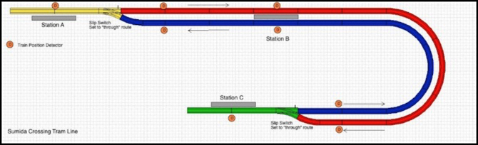
The Urban Station Tram Line, with three stations (Station C is under the elevated station)
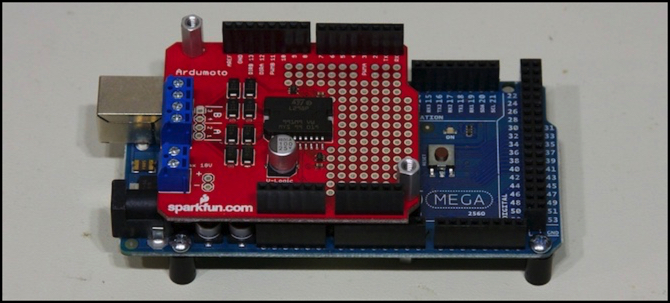
After quite a bit of dithering, I finally hit on the idea of using an Arduino as a controller. I’m not sure why it took me that long, as I’d read about using an Arduino for train control some time ago. But somehow I never put two and two together and realized it could be used to make a fully-automated tram controller. Until last month, when I was reading an article about Arduinos and the idea popped into my head. The photo at the top of the page shows the Arduino (blue) and two-motor controller (red) I’m using for development; I’ll eventually use a smaller Arduino installed on the layout (I could have done development on the small one, but they were sold out when I went to buy one). The total cost of all the electronics, including the power supply driving the trains, will be under US$100.
In case you don’t know what an Arduino is, it’s basically a $30 circuit board with a small computer chip of the kind used for embedded controllers (such as are found in things like automobiles and soft-drink machines these days). It’s not a fancy general-purpose computer, and it doesn’t have a disk, printer or any of the usual things you might associate with one. Instead it connects to a computer to be programmed (via a USB cable), stores one program in flash memory that’s permanent, and runs the stored program whenever it’s turned on, without any need for the computer to remain connected. And it has a bunch of input and output “pins” that can be connected to external electrical circuits (like photocells or motor-driving integrated circuits) to do things. It was designed to be relatively easy to use for non-technical “artists, designers [and] hobbyists” according to its website.
The programming language is based on C, which can be a bit daunting to the non-programmer. But there are lots of example programs out there to show you how it’s done, and in any case many Arduino applications require very simple programming. I’m not a novice programmer anyway, although C was never my favorite language (My first computer language was FORTRAN, back in the day, and I went to school when Pascal was in vogue for teaching; C I picked up years later, but never used it all that much). Anyway, for me the programming won’t be the hard part, and the outboard electronics will be very simple, so this should be easy, or if not easy at least not rocket science.
What I’m going to do is very simple, and I’ve written it up in more detail on another page, but I’ll summarize here. The other page will be updated as work progresses, and I’ll eventually post another musing when I finish the work. Right now I’m still working on the design, but I’m confident enough of success that I’ve acquired an Arduino and various other parts.
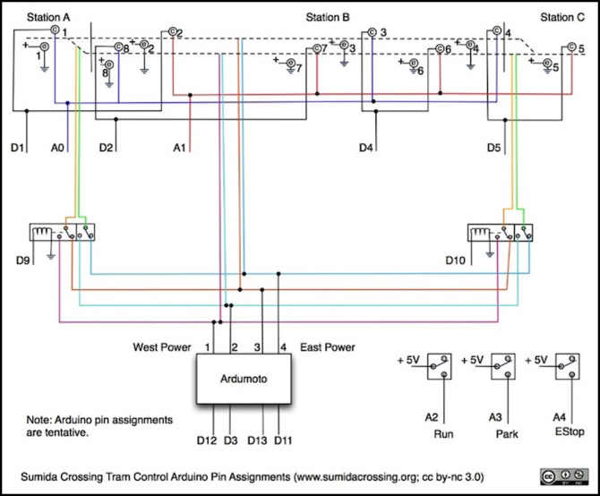
The idea is that the Arduino will connect to an external board (called a “shield” in the Arduino community; the one I’m using is Sparkfun’s Ardumoto Shield) that provides two motor power supplies. The Arduino will control the motor speed and direction using a total of four of its output pins (the Arduino Uno I plan to use has 14 output pins and 6 input pins). And it will be connected to two relays that allow it to change which of the motor power supplies is used for each station (that takes a total of two more pins). Eight train-detecting Infra-Red (IR) phototransistors (connected to four output pins and two input pins) are used to sense where the trains are. And three more input pins are used for simple controls to start and stop the system (Start, Park, and Emergency Stop buttons). That’s a total of 13 output pins (of 14) and 5 input pins (of 6). There are ways to more efficiently connect to sensors if I wanted more, and there are Arduino models with more pins (the Arduino Mega 2560 I’m using for development has 54 output and 16 input pins, but costs twice what the Uno does). Here’s a diagram of how these things all connect (note that it’s not a complete schematic yet):
So I think I have the basic design down. There are a number of details I need to work out: for example, the Arduino can detect when a phototransistor is being blocked by an object between it and a light source, but that’s instantaneous, and a passing train might appear as several blocked/not-blocked transitions. I’ll need some logic in the program to make a “blocked” state persist for the time it would take a train to pass the detector, regardless of the actual detector behavior. Not a hard problem, just one of several details I’ve yet to fully work out.
And I need to actually build a detector, or detectors, and the power supply control relays and see how they work in practice. The devil is always in the details.
There’s no sense of urgency. This is just one of several things I’m thinking about for the layout (like the grade crossing I haven’t done anything on since September). As opportunity presents, I’ll work on it further, and eventually get it working and installed. But for now, at least I have a plan for how to solve this problem. Time to work on something else for a bit.
*
Warning: The Arduino uses Pulse-Width Modulation (PWM), a type of pulsed power, to control DC motors. This is fine for most motors, if fact it makes them run better at low speeds, but “coreless” motors run at low speeds on pulsed power can overheat to the point of self-destruction. Most DC train motors aren’t coreless, but I’ve heard rumors that Kato’s Unitram motors (which are ultra-small motors developed to make cellphones vibrate by spinning a weight at high speed for a short time) are coreless. So if you’re using Unitrams, you might not want to take this approach.
Other website changes:
- Made some updates to various index pages to make the layout Electronics page and the separate “electronics for trains” material (which is on the Model Trains page) easier to find.
- Added photos of the Arduino to the Electronics photo album, and diagrams to the Diagrams album.
- Updated the Roster, Commuter EMU and Freight Locomotives pages with my new E217, EF65 and EF66.
Apple appears to continue having problems with iWeb comments, although it’s intermittent. If the comment window opens with a mostly white background and squished to the left side of the screen, it’s broken and won’t post a comment, but if it opens mid-screen with a tinted background, it should work. I’m suspicious that they changed something, and that each time I upload a new Musing I’m loading an old template that no longer works, which they then fix a day or two later, as it seems comments are broken for some interval after new pages are posted, but then start working. This looks like an Apple bug; hopefully one they’ll fix. Although the symptoms are similar to problems that have been reported in the past for iWeb related to domain name issues or incorrect software combinations, neither of those causes appear to apply to my site. Until this gets resolved, if you want to reach me and the comments are broken, you can always send email to the address on the Who Am I page.
== Comments from old system:
Monday, February 14, 2011 - 11:25 AM
Don
Very exciting! I look forward to seeing more progress on this. FWIW, all of the 20 pins on the UNO are bi-directional: They can be used as inputs /or/ outputs (and, if you are very clever, both at the same time). The only difference between what you are calling input and output pins is that the "input" pins can also optionally be used as analog inputs (vs. digital inputs that all pins can be used as). So don't feel constrained to only 6 inputs!
The other thing you might like to be aware of is that certain pins can be used as input interrupts, which could be useful for detection. That way you won't have to poll constantly. http://www.arduino.cc/en/Reference/AttachInterrupt
Thursday, March 10, 2011 - 02:22 AM
quinntopia
Great explanation on what the Arduino can do. My brother in law is an electronics engineer and order me some similar boards that TI is now putting out (and were a lot cheaper). He saw my layout and had all these 'crazy ideas' for how I could use this little board. I still don't understand a lot of it, but I'm starting to get it.....I think.
Tuesday, March 15, 2011 - 01:47 PM
Don
Jerry,
The TI Launchpad is pretty cool: $5 a piece, although the chips aren't quite as powerful as the ones in an Arduino, it's still a really cool board. You'll have to post about what you do with them!
