


Track, Turnouts and Servos
If you follow the RSS feed on the main page, you can see that my interest in signals continues. However today’s topic is about what signals describe: track, and in particular the turnouts, or track switches, or just switches, used to direct the motion of trains, although I do mention the relation to signals briefly. And yes, it’s finally a post about the layout, even if it is about the as-yet unbuilt future layout.
I’ve been spending some time thinking about how I’ll do turnouts on the new layout. As part of my overall design, I’m planning to use code 55 rail on a mixture of concrete and wooden tie track (I’m undecided between PECO and Micro Engineering). And I may custom-build some track to replicate slab-type track, which is used by both Shinkansen (sometimes) and in some newer construction for narrow-gauge track, particularly in stations and on viaduct. Although I dislike unnecessary work (and hand-laid track is, to me, generally more effort than it’s worth), I do plan to put substantial effort into getting the track to both operate reliably and look as prototypical as I can. And thus hand-laying some portion of it for appearance purposes may be worth the effort.
Note: some Japanese models have issues with code 55 track due to larger-than-spec wheel flanges, and I’ll need to do some testing. But most of my models are Kato, and they generally use low-profile flanges that should work.
I’m also planning for very wide radius curves, although I have not yet picked a specific standard or minimum radius. I want both Shinkansen and commuter stock to look good on curves, with minimal overhang. That means I need much wider curves than the minimum operating radius. I may skimp a bit for storage and yard tracks, including modeled layover terminals where trains are kept off-peak. But mostly I’m considering track radii in the 30” or larger (750 mm or larger) range. And that raises the related question: what type of switches do I want to use?
Standard NMRA-spec switches are rated by a number value (NMRA Standards and Recommended Practices, RP-12 but see also TN-12 in the same section for more background). That method is modeled after the way real switches are sized based on a frog angle, except that real railroads use much larger angles than model track, up to #24 or possibly larger for some high-speed turnouts. The NMRA defines scale dimensions for turnouts from #4 to #20, although commercial offerings tend to be #8 or smaller.
Frog numbers derive from the angle in a very simple manner: they are the ratio of divergence to distance (e.g., a #6 frog causes the diverging and straight track to be 1 foot apart at a point 6 feet from the frog, and two feet apart at 12 feet from the frog). Note that this is a constant angle, not a curving divergent track. High-numbered frogs thus have smaller angles and allow higher-speed operation. Per the NMRA, frog numbers less than 6 are recommended only for slow-speed track such as yards, due to potential issues at the frog even for through trains. Many available sectional-track “mainline” turnouts are #6 (equating to a 10° angle), simply because they take the least space of any with a sufficient angle for high-speed use.
On the prototype, a #6 is a sharp yard turnout with a 10 MPH (16 kph) speed limit (per U.S. AREMA standards, PDF), with #8 to #11 allowing 15 MPH (24 kph) but still restricted to yard use in most cases. Mainline track is unlikely to use less than a #12 (per this site), but per AREMA these are still limited to 15 MPH use. Also per AREMA a #20 is the standard for passing sidings, with #15 used where sharper curves (and shorter switches) are needed, such as at station tracks. A #24 frog is required to permit Limited Speed (50 MPH freight, 60 MPH passenger, or 80+ kph) use.
The Japanese MLIT standards aren’t as clear about speed restrictions. Station speeds are likely limited to 25 kph (15 MPH), the maximum allowed by a call-on signal, which are often used within complex stations where multiple trains from the same line may be in the station. Yard speeds may be as high as 45 kph (28 MPH) under some circumstances. In particular, the MLIT standards only talk about speed approaching the next signal, and not speed through an interlocking, so it is not clear if these signal aspects are really appropriate to crossover tracks located away from a station (stations have a nearby “next signal”, a mid-line crossing would not necessarily have one). However, examples of real-world crossovers outside of station bounds do exist, and are protected by home signals (on lines that have wayside signals), so clearly the signals are used to control passage through such interlockings. My interpretation is that signals apply speed restrictions that remain in force to the next block signal, but I need to find more real-world examples to study.
This makes me think that I want to use at least two different switch types, one for station sidings (which could be as sharp as a #6, although I lean to slightly longer ones, such as #8, for visual reasons) and a longer one for crossovers. I don’t think I’d bother to make narrow-gauge and Shinkansen crossovers different lengths, although on the prototype they would be.
An alternative approach is to use a constant radius curve through the switch rather than an angle. PECO, for example, uses this method in their turnouts. As a result, they can’t be described as conforming to the NMRA standards, even though many dimensions are the same and they will interoperate with NMRA-standard wheels and trains. PECO makes three sizes of turnout: Medium is 18” (457 mm) and Large is 36” (914 mm) radius. There is also a Small radius (12” or 305 mm), but that is too sharp for anything other than light rail use (I’m planning a light rail line, but that’s a topic in its own right).
According to this site, which has a lot of useful info on PECO turnouts, these all use #6 frogs. Remember that formally the frog number reflects the angle at the frog, and not the turnout curvature; the NMRA standards link the two, but working turnouts can be built that do not. PECO also has a set of curved turnouts in the two larger radii, as well as single and double-slip turnouts, crossings, Y and three-way turnouts and a double-crossover, although I anticipate only using simple turnouts (and possibly the crossover). Today, these are all available with either insulated and conductive frogs (“insulfrog” and “electrofrog” respectively), except apparently the crossover and 3-way, which are electrofrog-only.
The double-crossover is something I’d originally thought I wouldn’t use. It’s more complicated than just using four normal crossings spaced out, and while convenient for space-limited modelers, it’s somewhat unrealistic in the real world. Or so I had assumed. And then I started looking at maps with photo images of track, and discovered that Japan has the same lack-of-space problem that modelers have, at least in some places. The Chūō line between Ochanomizu and Suidobashi stations has no less than three of them, in a distance of less than 1 km. And I really want to include at least a portion of that line in my layout. So double-crossovers look like a requirement, or at least an important detail in a scenic sense.
Although I like what I’ve seen of PECO’s Large turnouts, I’m considering using something even larger for higher-speed crossings, particularly on Shinkansen. One option is hand-built switches using the Fast Tracks system, which provides for frogs up to #12. There’s a bit of a cost to the jigs and various tools, but I probably only need one or two sizes (e.g., #8 and #12) so that’s an acceptable expense. I might use them for the double-crossing also; Fast Tracks has a jig for a #8 double-crossing. That’s sharper than I’d like, but acceptable and larger than PECO’s version.
This is more hand-building, but I don’t plan to have many mainline switches, as they’re not that common on the prototype (Chūō line aside). Japanese stations generally use dedicated platforms rather than complex throat tracks with lots of switches, and use double track with unidirectional running, so crossovers are not common. While the Chūō line wasn’t the only place I found them, single crossings were used in a few other places, and for the most part trackwork avoided crossings unless there was something on one side that needed to be reached. At most I’ll need switches for express and local platforms, and a few branch or yard tracks (switches in yards themselves can be pre-built #6 to save space).
There’s another couple of things to consider. The first is linear space: when I used Kato’s Unitrack, a double-crossover was 31 cm (12.25”) in length. A #8 fasttracks double crossover will be 37 cm (13.6”), and a pair of single crossovers built using four #12 switches would occupy a total length of 105 cm (41.4”). This definitely biases me to use of the #8 double-crossover.
The second point is track spacing. As described on my flex track page, I’d planned to use a center-to-center track spacing of 26 mm (just under 1 1/32”). That’s a bit wide compared to the prototype, as standard spacing for a commuter line would work out to 23.6 mm. However, it’s probably the minimum spacing on straight track for reliable operation (the European MOROP standards recommend this spacing for a variety of conditions). If I use ordinary switches for crossovers, I can make them fit any spacing. But the fasttracks jigs enforce a spacing of 27.7 mm, so I would either need to use a wider spacing, or widen it when approaching a crossover. I think I can live with that, but it does make me wish for sufficient space to use ordinary switches.
There’s another complication to this that I haven’t fully worked through yet. There are basically two approaches to constructing the point rails in a model turnout. One uses a point rail for the diverging track that is slightly curved. The other uses one that is straight. The curved point rail provides for a more gentle transition from straight to curving track (similar to the use of easements I’ve discussed before). Prototype turnouts use straight rails for the points, likely because curving them consistently is hard.
Turnouts built using Fast Tracks (and similar hand-built track) use a straight point rail. At least some manufactured turnouts use curved rails, which is a reason to prefer them, particularly for smaller frog numbers where easement is more important. So I’m considering using PECO Large turnouts (#6 frog, but gentle curves) for places where I need more compact switches, and possibly using their Medium (also #6, but more sharply curved) in yards and hidden storage, places where space will be at a premium. But for most station and crossing tracks, I may make my own, in #8 and #12 sizes, and live with the straight rails.
Note: I can’t see any curvature of PECO’s large turnout’s point rails. The medium’s do appear to curve slightly. This may only be a real concern for #4 switches, which I’d avoid anyway.
Assuming I use #8 and #12 switches, in mainline use these would probably be signaled for Medium speed (Japanese “Caution”, 40 - 55 kph) and Limited speed (“Reduced Speed”, 50 - 75 kph) operation respectively, to add some operational variation along with the physical. Any #6 in signaled territory could then be treated as Restricted speed (Japanese “Restricted”, 25 kph). Both Restricted and Reduced speed signals require a four lamp signal head, although different kinds, providing a bit more “this is Japan” character to the layout. This assumes that the Japanese signal indications apply to “within an interlocking” situation as described above.
Throwing the Turnout
My inclination is to use powered frogs and to throw turnouts by some kind of slow-motion motorized system (i.e., not manual throws or solenoid-based switch machines) initially controlled from fascia switches, although later I might add other control methods. Powered frogs require a means of power switching that does not depend on the point rail contacts, as those are not reliable over time. But this seems worth the extra bother given that these will more reliably support short-wheelbase locomotives (some of my freight locos) and avoid flicker in lighted trains.
Some turnout motor systems don’t provide for switching track power to the frog, and others don’t work well with turnouts that have points connecting to the frog (since those may switch at a different time during a throw and cause a short). I had problems with that on my old HO layout using Tortoise motors when I switched to DCC, although that was partially due to the use of pre-DCC turnouts I tried to modify when they were already installed on the layout.
But an interesting solution to this problem that I’ve run across is the TAM Valley Depot Frog Juicer. It’s effectively half of a DCC auto-reversing circuit (it can reverse one “rail”, the frog, rather than two). It won’t work on DC. But for DCC it is relatively inexpensive at about US$14 per turnout, and the newest versions will work with PECO electrofrog turnouts without modifications to the point rails (or so they say, I’ll need to try one to see). And best of all, it’s powered from the track and uses screw terminals for any wiring (I’m a big fan of screw terminals), so wiring is simple and straightforward. They suggest double-sided tape to attach it under the layout.
These are essentially DCC circuit breakers. They trip at 1.7 amps, which is high enough to avoid accidental trips even with N-scale sound locomotives, but still low enough to work even with a 3 Amp DCC supply (I’m still thinking of using distributed small DCC power supplies, such as 3 Amp, rather than a centralized 5 Amp system or systems). And they’re solid state. Some cheaper auto-reversers use relays, and I’m not a fan of things going “click” under the tracks.
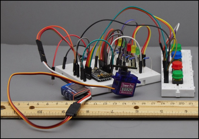
As for what to use to throw the turnouts, right now I’m inclined to use servos. These are compact, making them easier to use under complex N-scale trackage than the large stall-motor systems like the Tortoise. Servos have their own issues; they can be noisy, and the control systems may be fairly expensive. It’s also important to use them as positioning motors rather than stall motors, a distinction that seems to escape some people. Running a servo at stall is not only noisy and expensive in terms of power use (and thus power supply size), but also likely to burn the servo out in short order. These things aren’t generally designed to be used as stall motors.
As you can see from the photo at the top of the post, I’ve been playing around with servo control using an Arduino (that’s a 5V Pro Mini Arduino buried in the middle of the wiring, next to some LEDs standing in for a signal). I have the basics down now, and need to build a section of test track where I can try out this and other solutions with real turnouts, and see how well they work in practice. That’s probably my next project.
My servo page lists a number of possible control systems if I don’t make my own. For non-yard applications such as crossover pairs of turnouts or sidings, I could use either the Iowa Scaled Engineering MRServo-3 (US$20 each, with servo) or a TAM Valley SwitchWright with add-on slaved servo (~US$32 total for pair, pre-assembled but w/o servo). Both end up costing around US$40 per siding/crossing with servos, which isn’t a bad price, although it is a bit higher than a stall-motor solution would cost in bulk. If I roll my own with Arduino, I can get the cost per turnout under US$15 with servo (US$30 per siding, maybe even US$20), or on a par with the stall-motor solution. Maybe even a bit less, depending on the exact solution used.
Notice that I haven’t discussed DCC decoder functionality as a requirement. That’s because I lean to use of an external control bus if I want to tie these into some kind of external control system (e.g., JMRI on a computer). So I just need electrical switch contacts or 5V output & sensor lines that could be sensed and thrown by a bus-connected sensor/actuator.
Part of the reason for that is modularity. I don’t want my control system and the physical plant of turnouts and turnout controls to be intertwined. I could easily replace a computer and any centralized system several times over during the lifespan of the turnouts. And with the ongoing evolution of NMRAnet, recently renamed Layout Command Control (LCC), I suspect I’ll end up replacing any initial control bus at least once. These things need to be decoupled to the extent they can, and use standardized interfaces between them. Modularity is a good thing in designing complex systems anyway.
Another reason is that not everyone supports DCC as an option, or if it is supported it comes with significant cost. I want to avoid unnecessary cost until I’m ready to use such a capability, so making the basic control system non-DCC allows a simpler and potentially cheaper initial installation, even if the end total winds up being higher than doing a pure DCC solution from the start.
I’m going to investigate a number of servos and control systems, starting with a simple Arduino-based approach. As mentioned I already have a basic test program working, although it’s not functional enough yet to publish; I’ll eventually develop it into a library if I can get it working reliably. There are also others who have published control programs and I link to some of those on my Servos page.
But back to track: where I stand right now: code 55, big radius curves and large-frog turnouts, servo-controlled turnouts, and possibly some use of handlaid track in addition to flex track and pre-built turnouts to allow more prototypically gentle turnouts. It’s still early days, and the final plan may differ. But this is the result of a winter spent considering the issues, so it’s a fairly well-baked design at this point.