


Kato DE10 Notes and DCC Decoder Install
The DE10 has been the workhorse road-switcher in Japan since the 1960s. It’s still used today on non-electrified lines and in yards, as well as on work trains on electrified lines. Although a diesel locomotive, it is not a “diesel electric” like most such locomotives, but a “diesel-hydraulic”, meaning that instead of having a generator and traction motors, it uses a fluid transmission to send power to the five driving axles. And it has five axles to spread its weight, critical for some of the very lightly-built branch lines on which it operates.
Kato’s new (2009) DE10 model is a very nice locomotive, and one I want to have pulling work trains (and maybe a mixed freight) on my layout. That means I needed to add a DCC decoder, and Kato’s website suggested the DN163K1D is appropriate for this. It is, but it’s not quite a “drop in” decoder addition. At the same time, there are some details to add. Not content to do things by halves, and fearing it would go out of production, I bought two of the “warm region” models. Later I added a “cold region” model (both kinds can be found operating in Tōkyō).
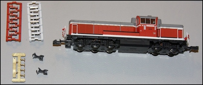
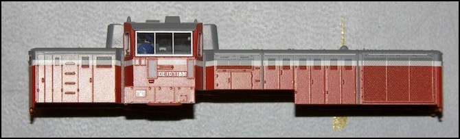
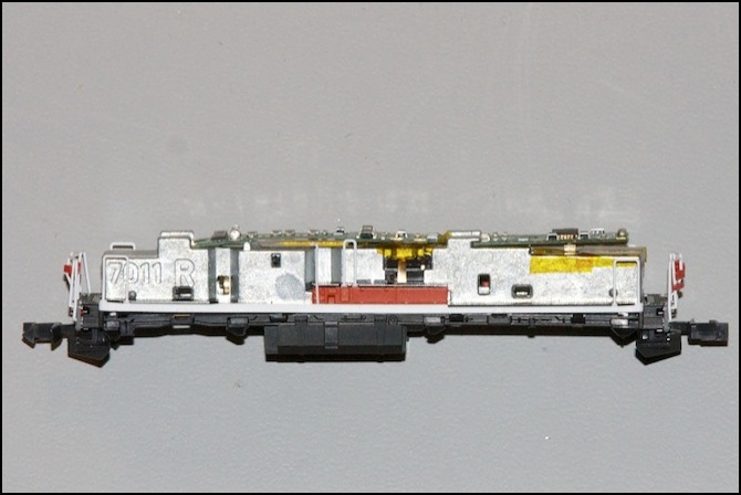
DE10 with red and while number boards, dummy couplers and (gold detail; horn)
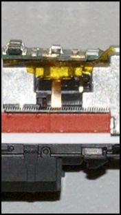
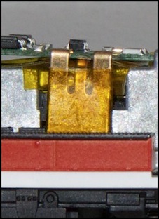
The gold part mystified me at first. It only comes with the “warm region” version of the module, and only that cab has the holes for mounting a pair of them (and they’re nearly impossible to install). It looked like it might be a horn (and it was), but not quite, and why was it only on the “warm region” version?
Daisuke Ueno, proprietor of the Japanese blog I mention below, graciously provided me with a comment about the gold part: it is a horn (called a “whistle” by Japanese railfans). The Cold Region models have a covered horn, which is why there isn’t a part for it.
He also recommended the decoder he used, available from the New Generation of DCC site, the DE22x6_DE10K 6FX, which a few folks on the JNS Forum have reported successfully ordering by sending email to the address on the website (the site’s all in Japanese, so judicious use of Google Translate or similar may be needed to find the address, but the person who runs it understands English). See this thread, this thread and this thread for comments on experience with them.
Another provider is Kumata, which is selling ESU decoders programmed with Japanese-prototype sounds (including the DE10). There are some fairly complicated instructions for ordering from outside Japan on this page, but they do take Paypal (thanks to bill937ca for the tip). I don’t know of anyone who has ordered from them, as the prices are quite steep: 21,000 yen, or $262 at today’s rates, before you add shipping, compared to $127 from U.S. provider TrainTek (but TrainTek and other domestic distributors don’t have Japanese sounds).
Prototypes, Paint and Numbering
This isn’t a model for rivet-counters, at least not if you’re modeling the twenty-first century. Basically, this is an older paint scheme, and while many locomotives still wear it, they’re a rapidly dying breed. Also, note the orange bracket on the front and rear handrails. These are for steam lines, and all current DE10s have had their steam generators removed (and those built after 1973 never had them at all). This is a detail from the transitional era when DE10s replaced steam locomotives hauling passenger trains, and needed to supply steam heat to the cars. If you’re modeling JNR (prior to the creation of JR in 1987), it’s likely an accurate model.
Note: those orange steam-line brackets are a real pain, they are either molded to the handrail or glued, and impossible to remove without breaking the handrails. I cut one of them into really tiny bits with flush cutters, and still couldn’t get all of it off. After that, I resolved to ignore the other ones and left them alone, at least for now.
Number boards need to be applied. Kato supplies four sets of road numbers, in red (for the cab sides) and white (for the ends). Although I thought I’d seen some locomotives in this paint scheme with red number boards on the end, I later couldn’t find any photos of this, and may have been mistaken. In any case it isn’t an option with this model unless you want to repaint it.
The snap-in number boards come with four road numbers, and the cold-weather and warm-weather models have different sets, so you could have eight uniquely numbered locomotives. For the warm region model, the numbers supplied are: 1188, 1192, 1574 and 1581. For the cold region, they are 1197, 1202, 1592, and 1598.
Two of the “cold region” numbered prototype DE10s wear the same paint as the model, the others have been repainted in the new scheme. DE10 1202 was wearing the old paint scheme, and working at Tabata yard in Tōkyō, as recently as March 2010, but was not equipped with either the plow or circular wipers. DE10 1598, which is equipped with wipers and plow, had this paint scheme as of December 2009, but appears to be assigned to Toyama, on the Sea of Japan coast. So there’s really only one option for a Tōkyō DE10 to be strictly prototypical, and you can’t get it by buying one locomotive as you need a warm region model and the numbers from a cold region model.
In fact, the warm-weather models are even worse than the cold-weather ones, as at least three of them wore a blue-and-gray color scheme prior to being repainted in the new gray-body scheme around 2008-2010. If they ever wore the paint scheme of this model, it was a long time ago.
Oh well, my version of Tōkyō isn’t all that exact anyway, so I can live with some of my locomotives lacking a prototype with the same number, paint, and style. On to adding numbers.
On each series, the two lower numbers (1100s, 1200s) represent models built from 1969 to 1973 (per Japanese wikipedia) originally fitted with a steam generator for passenger use (per wikipedia), although those were removed and replaced with cement blocks (for improved traction) long ago. The two higher numbers (1500s) reflect locomotives produced from 1970 to 1977, which were built without the steam generators. Plenty of both series still remain in active service (in fact, all eight numbers Kato supplied appear to still be active), so the choice is really arbitrary. I took the first and last, mostly as it was easier to cut them off the sprue.
Note: slightly larger versions of the photos shown here can be found in the DE10 Photo Album.
Disassembly and Detailing
Two important tips:
1) Cut all four number boards you’re going to use off the sprue and trim them before installing the first. I managed to break one, after already installing two of the boards; fortunately I had a second train with the same numbers, so I was able to use one from that set instead of trying to remove the snapped-in number.
2) If you’re going to install a driver figure in the cab, as I did, do that first, and put the cab back together, before adding the numbers on the side of the cab. Installing the cab will hit the tab that holds the number board in place, popping it out (and across the room; I speak from experience).
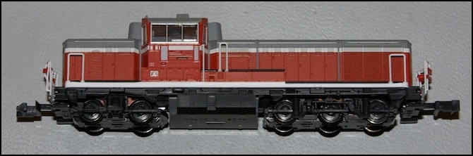
Body before number added (note slot in recess below cab window)
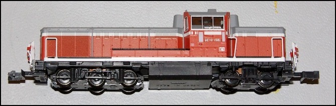
Body with “DE10 1581” number board added.
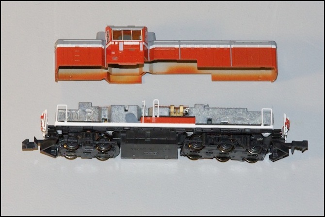
Body Removal
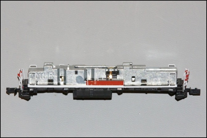
The body comes off easily. The trick is to realize that the running boards and railing are part of the base, not part of the body, and it’s the cab and hoods that lift off. Once it’s off, you can see the plastic headlight assemblies, and the four orange tabs inside the hood that hold the cab onto the hood assembly. You can also see the lightboard attached to the weight.
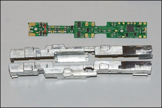
The weight is a typical Kato “split frame” design. The two halves are held apart from each other, and each has a brass strip along the underside that makes contacts with brass tabs on the trucks, so each half-frame is at the same voltage as the rail below that locomotive side. This means you need to ensure the motor and decoder are insulated from the frame. Fortunately the motor body is mainly made of plastic and normally holds the two half-frames apart, so no further insulation is required there. You do need to be careful not to bend the frame (which is soft metal, probably some zinc alloy) so that any part of it touches the other frame once the locomotive is reassembled.
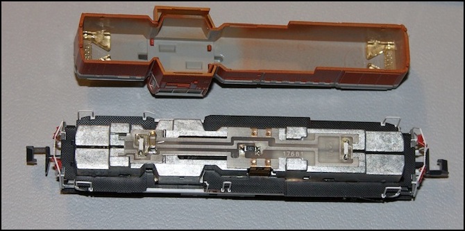
DE10 with body removed, showing lightboard, and two of the four tabs holding the cab to the hood.
Cab and Driver
The cab is moulded with a base at the window line, hiding the weight inside the body. There is a small amount of detail moulded in, including the driver’s seat back and a lump for the control stand (on both sides of the cab; regardless of which hood is the front, the driver can always sit on the left side, nearest the front window, although I’ve seen drivers working from the right, rear, position in some images).
While I had the body off, I added a driver, using a figure from Preiser’s Japanese Railroad Personnel (79207) set. This is a 1:160 figure, but the difference from the 1:150 model is unlikely to be obvious with just the head and torso showing through the window. In fact, the head and torso is all there is, as I had to remove the legs to install the figure, since the cab does not extend below the window line. Kato also makes several 1:150 train crew figures, and I could have used one of those if I’d had one.
Installation required popping off the cab roof, but it’s held in by four small tabs that can be released from inside the body shell with a very narrow screwdriver. A small (very small) dab of Woodland Scenics Accent Glue was used to attach the torso to the locomotive. Once that had dried a bit, I snapped the cab roof back on.
Cab with driver
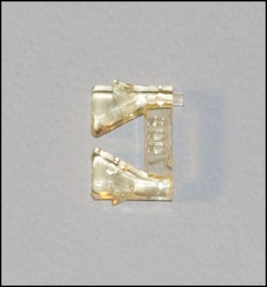
The “Warm Region” Gold Horn
You get four of these with the “warm region” model, and the cab roof has holes for mounting two of them. The “cold region” model lacks these and does not include the part. The sprue also includes a tool for attaching the part, but so far I haven’t been able to successfully install one (and I’ve lost two in “fly across the room” accidents; they’re small and spring away for quite a distance).
DCC Decoder
Kato recommends the Digitrax DN163K1D decoder for the DE10 on one page on their site (it’s a dynamic page, so I can’t link to that recommendation). This is essentially the same decoder as the DN163K1B except that it uses surface-mount LEDs on the board rather than external LEDs on leads. It’s also the same as the DN163K1C, except that the “C” has brass clips soldered on, and they’re oversized for the DE10 (plus it would be hard to install the lightboard with them pre-attached). Use the DN163K1D.
As noted above there are some better options if you want to order from Japanese manufacturers, but these are a little more complicated than ordering trains from one of the big hobby shops there.
However, the DN163K1D isn’t a drop-in decoder install for this locomotive. There are three problems:
Problem 1: Size
The decoder is longer than the lightboard, and places the surface-mount LED in the wrong place to illuminate the headlights at the long-hood end. When installing a DN163K1D in Kato’s GG1, the instructions indicate that you need to remove the light pipe at one end of the model to accommodate this, but the DE10 light pipe is part of the headlights themselves, so it will need to be modified rather than removed. One Japanese site illustrates using a shorter decoder (available in Japan) with the addition of surface-mount LEDs, however it’s not clear that this solves the light-pipe problem (it mainly seems to be done to address issue #2).
Another option would be to replace the long-hood SMD LED with a LED on leads, placing it above the middle of the long hood, where the old lightboard placed its LED. That’s a bit more work, but it was my fallback option if all else failed. Fortunately, it wasn’t necessary, and I solved the problem by cutting down the light-pipe to fit.
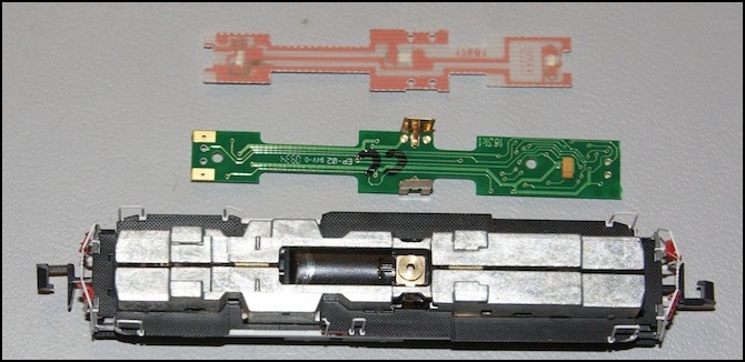
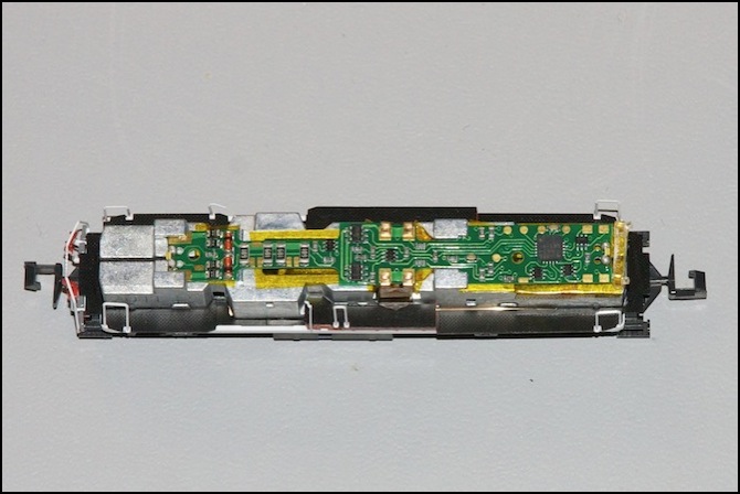
DE10 with DN163K1D (green) and lightboard (white/copper)
Problem 2: The Resistor
As can be seen in the photo above, there’s a surface-mount resistor (the brown box on the right) on the underside of the long-hood end of the decoder.
Looking at several online photos of other models using the DN163K1D, all have a hole or recess in the weight where the resistor would sit. The DE10 lacks such a recess. One picture on the Japanese site with an untranslateable caption shows the decoder angled up, but I think that was a “don’t do this” picture as there doesn’t appear to be room under the hood for this arrangement. This is easy enough to fix: simply file down some of the soft metal end, or mill it out with a drill or Dremel, but it means taking the mechanism apart (so metal filings don’t fall down inside).
Problem 3: Insulation
Unlike some other models that use this decoder, the weight does not have a hollow below the clips that hold the decoder, to keep it away from the metal of the weight. This wasn’t an issue for the lightboard, as all traces were on the top of that board.
The gold contacts on the narrow-hood end of the decoder need to touch the weight (they appear to be the power pick-ups). However, there are exposed contacts on a number of the through-board holes that could potentially also short out. Digitrax doesn’t mention this as a problem on their GG1 installation instructions, but the board appears to be held slightly away from the weight, and they do mention putting insulating tape in one place on their DD51 installation instructions. While the DE10 holds the decoder up somewhat, so this may not be an issue, I decided to err on the safe side and made liberal use of Kapton tape to insulate the weight.
You’re going to need some of this anyway, to insulate the motor clips. (you can get a roll of this from Amazon, or any good electronics store). It’s important that the two brass “motor contacts” don’t touch the weight, but only touch the tabs on the motor itself. Unfortunately, they do touch the sides in places. The above-noted Japanese site showed some insulating tape placed on the edges of the contacts to avoid this problem, and that’s what I did.
The Install
First, take the whole locomotive apart. This isn’t too hard, but beware the trucks (which tend to come apart), and don’t lose the little white linkages which connect each truck to the flywheel) and the brass strips on the underside of the weight (which are easy to bend, and near-impossible to straighten). Also, if the coupler assembly unsnaps from the frame it can come apart (not hard to fix, just a nuisance), and it doesn’t seem to snap back onto the frame very reliably.
Step 1: pull the body off; it slides away from the walkway and undercarriage with a gentle tug.
Step 2: lift the walkways away from the undercarriage (small bumps on the weight tend to hold it in place, so a mild amount of prying is required, but it comes off easily).
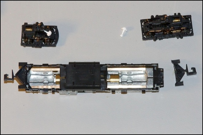
Step 3: take off the trucks. This is done by gripping one firmly by the sides (very firm, or you’ll just pull the truck apart, which is a nuisance to put back together and you might lose a gear) and twisting, while holding the weight firmly in the other hand. Be careful not to lose the driveshafts (white part). The coupler assembly may get knocked off (as the one on the right did) in the process.
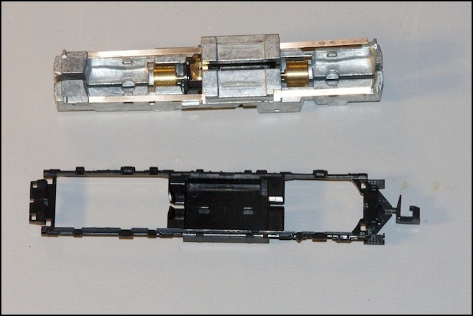
Step 4: take the undercarriage off (pry the gas tank away from the frame). This is all that holds the two halves of the weight together, and they may fall apart now. When the frame comes apart, note how the plastic tabs on the top side of the motor stick into holes in the weight. You’ll need to put them back there when reassembling, and it’s not obvious. Also note how the motor is essentially suspended inside the weight. You don’t need to add any insulation here, as no part of it that’s conductive touches the weight.
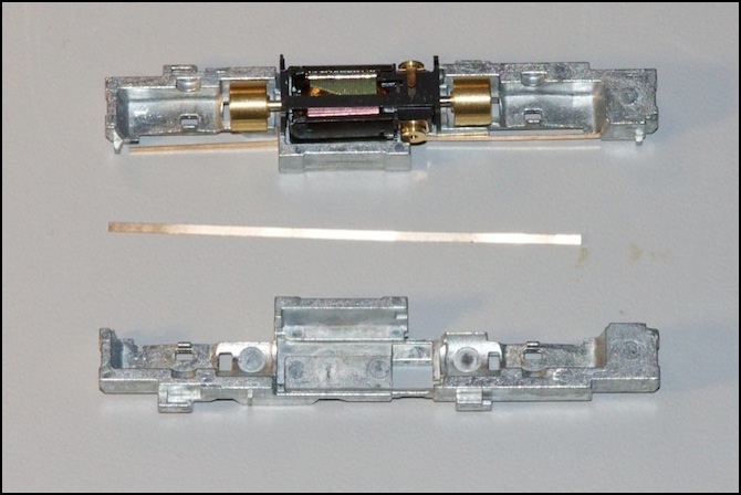
Step 5: remove the brass strip from each side (be very careful not to bend it), but first take note of where it fits into the weight, and where the ends go. As shown on the top one above, they should just overlap the point where the metal frame curves down at each end.
The problem: surface mount resistor (brown box at right end).
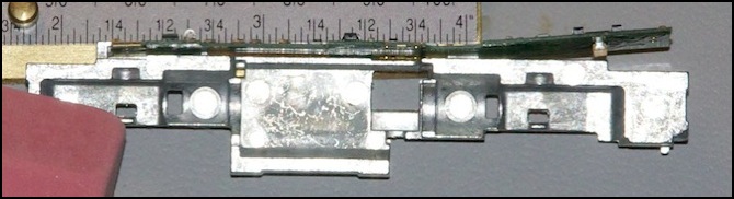
File the weight down to make room for the resistor, then clean it well to remove the filings. I clamped the weight lightly in a vise (not too hard, or the weight will bend; if it does, you can gently bend it back, but too much of that and it could break) and filed the end down with a metal file. A Dremel with a grinding wheel would have been faster, but I prefer to take my time and be careful. After that, I washed the weight and my hands with soap to remove the filings, then dried both throughly. I let the weights sit on a paper towel for a couple of hours to remove any remaining moisture (blasting them dry with compressed air also works).
Step 6: filed down weight (note: make sure the two halves are both straight when you’re done, as if they’ve bent, they could short together once the model is reassembled).
Step 7: reassemble the weight, motor, brass strips, undercarriage and walkway (reverse of disassembly)
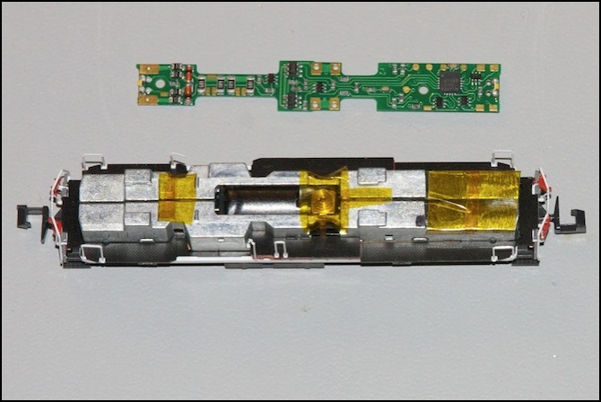
Step 8: insulate. It’s possible the circles that look like conductive metal on the underside of the decoder are varnished and won’t short against the motor, but even if they are this could rub off. I added Kapton tape liberally to insulate the weight. Note that the far left then needs to be bare where the decoder slips under the metal tabs to make contact (that’s the power pick-up for the decoder).
Note the tape above the circular contact on the motor. I bent this down over the sides, but only by about 1 mm, as you need to leave most of that side open to contact the brass tab you’ll attach to the decoder.
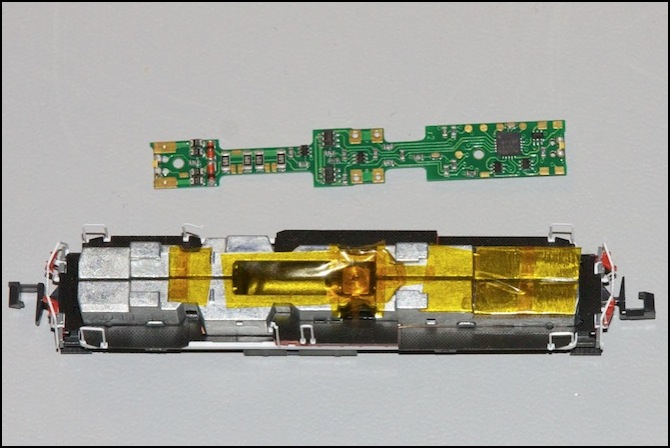
Step 8b: more tape
Step 9: attach the decoder.
Note that the left end is at a sharp angle. This is because the decoder, unlike the lightboard, rests atop the two metal bumps on the top of the weight, rather than snapping down to the left of them (compare lightboard photo at the top of this page).
Step 10: insulate the brass motor contact clips on their sides and back (but not the inside face!), insert into frame side so that the motor tab is touching the uninsulated inside face. Note that the edges of the brass clip need tape wrapped around them, as they WILL touch the weight.
Step 11: Snap the trucks back on. Make sure you insert the white driveshaft into the truck first if it fell out, that place its other end into the hold on the flywheel. Make sure it goes in smoothly; if you force it, it can snap (I broke one, so one of my three DE10’s presently only has one driven truck)
With the trucks back on, put it on the track with a DCC command station set to address 3, and test it. One of the two LEDs should be lit (hit F0 if it isn’t; sometimes this defaults to off), and they should change when the direction is changed, even if the throttle is at zero. Run the locomotive back and forth a bit, and make sure it sounds normal. If not, or if it’s not working, you’ll need to figure out if there’s a short somewhere (most likely cause of it not working) or some other problem.
Before you can put the hood back on, the long-hood light-pipe needs to be shortened radically. But to do that you need to take the light assembly out of the hood, and that’s hard to do. I managed to break one of the two lenses in the process, but only slightly and the resulting assembly still worked pretty well once reassembled. The trick seems to be a combination of pushing from the outside (using a paper clip) and prying on the inside (with a jeweler’s flat-bladed screwdriver)
Step 12: remove the light pipe (note the lens on the top right, and the missing (broken off) lens on the lower right).
The two angled parts should be cut off (flush-cutters used to take model parts off a sprue work well) and then the bar shape needs to be filed down to about half its original thickness, otherwise it will hit the decoder when the hood is reattached, and cause it to make poor electrical connection with the weight.
Even if you break the light-pipe, don’t despair. The LED actually works fairly well with no light-pipe at all, although you get a brighter, more focused beam if it’s undamaged.
Assembled decoder, with filed-down light pipe resting atop weight next to decoder (right end)
Step 13: snap the light pipe back into the hood (it may only loosely fit, if so just rest it in place and let gravity keep it there while you slide the weight into the hood. Make sure the hood snaps down all the way (it should rest against the walkway piece, without any of the weight showing.
Note: if you’re going to add a figure to the cab as described above, do that now if you didn’t do it already.
Analog Operation
One last note: although Digitrax decoders are “compatible” with DC layouts, I observed erratic behavior when trying to run at prototypically low speeds on DC after installing this decoder. The speed seemed to vary slightly and the engine made a “pulsing” sound, and it just didn’t seem as smooth. I quickly stopped, as I don’t plan to use the converted locos on DC anyway.
