


Simple LED Intensity Control
A Light Emitting Diode emits light at an intensity that depends on the current passing through the LED, not the voltage. Another way to say this is that a LED is a current-driven device rather than a voltage-driven device. But how then do you control the intensity? This page collects a variety of solutions to the problem. This page is somewhat specific to small white LEDs used in lighting model railroad scenery (street and building lights), but to a degree it can be applied to LEDs used for other purposes, as long as you take into account their voltage and current characteristics.
The simplest circuit uses variable resistance, adding only one component (a rheostat) to the usual two (LED and resistor). It’s not the best circuit, although it does provide some control. There’s a tweak to this that improves it slightly, but a better solution is to use three added components (transistor, potentiometer and another resistor) in addition to the usual two. Even that, although good, has it’s limits.
If you really want to precisely control a LEDs intensity, PWM from a microprocessor (or an oscillator circuit) can be used, as can specialized variable-current circuits, but this gets fairly complex, and the intent of this page is “Simple” LED intensity control, so those options aren’t covered.
Note: for the examples below, I’m using a specific LED in several examples so that I can reference its data sheet. The LED is a Wurth WL-SWTP surface-mount LED (Digikey part 732-5658-2-ND). Although rated for 40 mA, according to its data sheet, it draws 5 mA at 2.8 Volts, climbing exponentially to 10 mA at 3.0 volts and 30 mA at 3.3 volts. Luminosity is roughly linear with current (not voltage), rising from about 2 lumens (lm) at 5 mA to 4 lm at 10 mA and 10 lm at 30 mA (it’s not quite linear at the high end). This is a fairly typical LED for structure lighting, small but moderately bright (just under 1,000 mcd), with a broad (120 degree) viewing angle. You can get much brighter LEDs with reasonable currents today, but they tend to be too bulky for N-scale applications (even HO might be problematic for a 5mm LED).
It’s a bit too high-current for microprocessor applications, but in simple circuits with just resistors (or things like transistors) that’s not going to be an issue.
For others, I’m using a generic large (5 mm) LED I bought at the local electronics store (which wasn’t clearly identified as to part number) or talking about a LED model that came with my SPICE circuit-simulation software.
About LEDs
This is a brief summary, for more detail see my LED Lighting for Modelers page. If you don’t care and just want to see the circuits, skip down to the Intensity, Resistance and Control section.
LEDs are a semiconductor, a diode to be specific. Electricity can only flow through a diode in one direction, from the positive (anode) contact to the negative (cathode) contact. On larger LEDs, the cathode is usually marked by a flat spot on the side of the LED or by having a shorter lead. On small surface-mount (SMD) LEDs, there is no standardized marking for anode or cathode.
LEDs have a specific voltage they operate at, called the “Forward Voltage” or Vf. If you give a LED too much voltage, the semiconductor junction will fail, and the LED will go dark, forever.
Note: the forward voltage is not exact. It will vary some between individual LEDs of the same type. It also changes with temperature. Both of these effects are relatively small, so we can normally ignore them and treat forward voltage as a constant.
LEDs also have a maximum allowed reverse voltage, which is often 5V. Apply more than that, and the LED fails, again permanently. And a protection resistor won’t help, because it only reduces voltage when current is flowing. If you are using AC or want to guard against reverse polarity, you need a normal diode in series with the LED to block reversed voltage.
Normally, LEDs are operated on DC, and a resistor (a “current limiting resistor” or “dropping resistor”) is placed in series with the LED to reduce the supply voltage to the LEDs forward voltage. If Vf = 3.3V, as in our example white LED, and the supply voltage is 12 V DC, then 8.7 volts needs to be removed. LEDs have a rated current, and Ohms law (V = IR) gives the amount of resistance needed to “use up” a specific voltage. Removing power like that is wasteful, so often multiple LEDs will be placed in series with one smaller resistor. For example, three of those LEDs would use 9.9 volts, so the resistor only needs to eliminate 2.1 volts, which is much less wasteful. And wasted power is heat, something to avoid having close to plastic models.
[insert led graphic here]
Using the example LED, R = V / I = 8.7 / 0.030 = 290 Ohms. Resistors come in standard sizes, and have variability ranges called their “tolerance”. A 300 Ohm resistor is one standard size at 5% tolerance, but 300 - 5% = 270, which is less than 290, so that wouldn’t be safe. It would work for some “300 Ohm, 5%” resistors, but not all. So round up by the error range. At 10%, the next size up is 330 Ohms, and 330 - 10% = 300, which would be safe. While most resistors these days are made with fairly good tolerances (often just 2%), examples typically assume 10% just to be safe, and I’ll do the same here.
Oversizing resistors works because LEDs will actually reduce their current with less voltage, to get back to the desired Vf, or as close to it as possible. The forward voltage will always drop a little as resistance increases, but it’s exponential behavior, so changes become smaller as you add more and more resistance.
So if the resistor is really 330 Ohms instead of 290, the LED will draw a bit less current and be a bit dimmer. But the eye’s response to intensity change is complex, so in practice a human won’t notice the difference unless you reduce intensity (meaning current) substantially. That puts some limitations on how well simple resistance changes work, as we’ll see below, but it also means that slightly oversizing a resistor (e.g, by 20% of so) doesn’t have as much impact as you might expect.
Don’t forget the power rating. P (in Watts) = VI, where V is the voltage dissipated in the resistor. So for the above example, P = 8.7 x 0.030 = 0.111 watts, or 261 mW. That’s more than 1/4 W, so you’ll need a 1/2 W resistor for this circuit to work long-term. One trick to deal with this is two use two smaller resistors in sequence. Each drops some of the voltage, so they will dissipate less power and need a lower rating. It’s more work to wire up two than one though.
This is one of the problems with driving LEDs using 12 V power, and why it’s often preferable to use a 5V supply. I’m using 12V for these examples since it’s a common layout voltage, but if you are designing a system specifically for lighting, using 5V may be a better choice. And there are a number of inexpensive 5V power supplies available now, thanks to the popularity of microelectronics.
To operate the same 3.3V, 30 mA LED on 5V, we need to drop 1.7 volts. R = V / I = 1.7 / 0.03 = 57, rounded up gives us 68 Ohms. P = 1.7 x 0.030 = 0.051 (51 mW), so even a 1/4 W resistor will work fine in this case.
Resistance and Dynamic Resistance
It’s tempting to think of resistance as a constant. Resistors always have the same resistance, after all. And many other things, like wire, do too. But LEDs break that rule. The resistance of a LED is not constant, it varies as voltage (or current) is varied. This is called Dynamic Resistance. A consequence of this is that Ohm’s law doesn’t work for LEDs themselves.
Take the case of our typical white LED drawing 30 mA at 3.3 volts. If Ohm’s law applied, the resistance of the LED would be R = V / I = 110 ohms. And thus we’d know that if we gave it half the voltage (1.65V) it would draw half the current (I = V / R = 1.65 / 110 = 0.015 A = 15 mA). But it doesn’t. Apply half the voltage and the LED draws 0 amps and won’t light (roughly; real LEDs are harder to predict than the diagrams make it appear). Apply 3.0 volts and instead of 27 mA it will draw about 10 mA, so it lights, but significantly dimmer than you might expect from a 0.3 volt change (the eye doesn’t react linearly either, so the change may not look as substantial as it really is).
This is because the resistance of a LED changes with the applied voltage (and/or current). This is called Dynamic Resistance. That’s a number that’s hard to calculate, so we find ways to work without knowing that characteristic of a LED.
LED data sheets will usually include a forward current versus forward voltage graph: look up your applied voltage, and you get the current (or vice versa). The problem then becomes one of figuring out what voltage is being applied to the LED if that voltage depends on the current, as it does with a dropping resistor type of circuit.
Remember that 290 Ohm resistor was for the specific current of 30 mA. Put 27 mA through it and it only drops 7.8 volts rather than 8.7, applying 4.2V to the LED, which causes the LED to draw a lot more than 27 mA, which causes the voltage lost in the resistor to increase, reducing the current in the LED… An equilibrium will be reached, where current is balanced by voltage, but exactly what those are isn’t easy to predict. This makes using voltage sources with LEDs somewhat inexact. This is when you need to wire up the circuit and break out your multimeter if you want to know what’s going on; there aren’t any simple formulas to help.
Back on LEDs and the problem of using voltage to control them: there are also circuits you can use to deliver a specific current to the LED. The problem is that they’re a bit more expensive than a simple voltage source, so they aren’t used all that often, and least not in our kinds of simple modeling applications. This is a problem, because current is what really matters when you want to control intensity. So intensity controls either need to use current sources, or be somewhat inexact, as we’ll see is the circuit designs below.
Modeling Circuits
If you want more accuracy than simple formulas, you could turn to modeling software. Most modeling software for circuits, maybe all, is based on a program from the 1970’s called SPICE. This program uses a text file list of circuit components and their connections (the “netlist”), along with a database (also in text) of component models with dozens of characteristics. It basically looks at the behavior of electrons in semiconductors. Which means that it’s very accurate. It’s also not terribly user-friendly, and modeling a complicated circuit can take a surprising amount of time on even a modern computer (imagine how slow it must have been 40 years ago!).
Modern versions often have a graphical user interface (GUI) that is used to create the netlist, although some expect to get this from an external program (like the PCB-layout program, Eagle).
One problem with modeling LED circuits is that individual LEDs have a lot of variability, and most software only has models of a few “generic” LEDs, so you can’t necessarily get good numbers that way. Sometimes you just need to build the circuit and measure it. Modeling software is also really hard to use without experience; it’s mostly written by electrical engineers for electrical engineers, and they don’t spend a lot of time on user-interface design. Even with these limitations, it can be handy to rough-in a solution, if you’re willing to put in the time to learn it.
I’ve used a variety of modeling programs over the years. LTSpice is my current (2016) favorite, but the Mac version of that is particularly painful to use (it’s powerful, but not at all obvious).The Windows version is a little nicer, and possibly a good choice if you use Windows although there are many other options there. A simpler choice for Mac users is iCircuit (search on the App store); it’s somewhat limited in what it can model, and not updated very often, but much easier to use. It’s also a commercial product, and LTSpice is free. I have both, but I find myself using LTSpice every time I need to model something, now that I’m familiar with it.
Intensity, Resistance and Current
As mentioned with the example above, brightness of a LED is roughly proportional to current, which increases exponentially as voltage rises from the minimum necessary to light the LED to the maximum before the junction fails. Because of this, a linear change in resistance does not provide a linear change in intensity. This makes a brightness control for a LED a lot more complicated than you might suppose. As we saw with the example, doubling current from 5 mA to 10 mA doubled the LEDs intensity from 2 lm to 4 lm, but this was done with the voltage only changing by 0.2 Volts.
Since illumination is typically being done for viewing by humans, we have to consider how the eye reacts to light also. And the eye’s response isn’t linear. At half intensity, the eye perceives only a 30% reduction. At 10% of full intensity, the eye perceives only a 70% reduction (note: those percentages for perception assume the eye has time to adjust to the light, they don’t apply to immediate changes).
These two effects are additive. Double resistance and real intensity drops by less than half, and the eye perceives even less change than that. Resistance changes alone make a poor intensity control.
Intensity Control Via Rheostat
A rheostat is a variable resistor. These days those aren’t sold as separate devices very often, so instead you buy a potentiometer (pot) and use two of the three contacts. Here’s a simple intensity control that uses a pot in series with a fixed resistor. The fixed resistor is sized to reduced voltage to Vf at the maximum (i.e., the rated) current for the LED. This way when the pot is turned down to zero resistance the LED won’t be overloaded (not all pots will go to zero, so sometimes this can be omitted, but the pot I used went to zero).
Note that when using a pot as a rheostat, we don’t connect both ends, only the wiper (usually the center contact) and one end. Sometimes this is drawn as the loose end also connected to the wiper. That doesn’t change the operation of the circuit at all, and is unnecessary work to solder it, so I don’t do that.
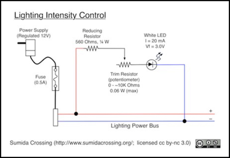
Note: the above circuit is for a 20 mA LED. Many white LEDs are 30 mA or 40 mA, and you’d need to reduce the Reducing Resistor value to drop the same amount of voltage, but the power dissipated (and hence the resistor rating) increases for those, since it depends on voltage and current, not on resistance.
I built a test version of this circuit. I had to use a slightly different LED from the example above: a large (5 mm) white LED putting out 30,000 mcd that I found at a local electronics store. It had a Vf of 3.2V and current rating of 20 mA though. Minimum required resistance was 440 Ohms, and I strung together a pair of 390 and 68 ohm resistors in series, using 2% models so the resulting 458 Ohms was a safe value. The potentiometer used was one I had on hand for use with Arduinos, with a 10K Ohm range and a linear taper. I tested the pot, and it went from 0.8 Ohms to 10,230 Ohms according to my multimeter, and the halfway point was at roughly 4,966 Ohms, so it was fairly linear. Another one of the same type had very similar specs (0.7 to 9,890, with a midpoint around 4,873).
Does this work? Yes, but not very well. With the pot at 0 Ohms the LED was at full brightness and drew 20 mA per my multimeter. Turning the pot about 60 degrees (out of the full range of 270) reduced light substantially and the current to 5 mA (with this LED, even at 5 mA it’s still quite bright). Turning it down to about the halfway position current dropped to around 2 mA, but brightness barely changed. Turning it all the way to 270 degrees current went to 1 mA, but it was still lit. Dimmer than at 5 mA, but not close to dark.
The maximum benefit came as the current was reduced to about 2.8 mA, below that point turning the pot didn’t have much visible effect. That current was reached as a pot resistance of 2,957 Ohms, or about one-third (90 degrees) of the 270-degree range. A 3K pot would have been sufficient, and would have provided a finer degree of control, but those aren’t very common.
The problem is that this approach is linearly changing resistance. With a 1 Amp current going through 10,678 Ohms of resistance, the resistors combined are dropping 10.7 volts of the 12.0 volt source, so they’re still applying 1.3 volts to the LED. That’s low, and a less-bright LED might appear to be off at that voltage. When you turn it up to halfway, the 5,406 Ohms of resistance and 2 milliamps of current is supposedly dropping 10.8 volts; it should drop the same or less than at full resistance, so I expect the current of the two settings wasn’t exactly 1 or 2 mA, but we’re at the limits of my meter. In short, as resistance increased from 5K to 10K, the LED compensated almost exactly by reducing current to keep the voltage similar.
Here’s what a simulation shows for the current in the circuit as the pot is turned up from zero Ohms to 10K. I had to use a generic 20 mA LED for this, as I didn’t have a SPICE model of a 20 mA white LED (I need to find or make one, but that’s a project for another day). So it’s not going to give exactly the numbers I measured, but it wasn’t far off. As you can see, the first 2K of change in resistance causes almost all of the drop in current, after that, current does change, but not by much.
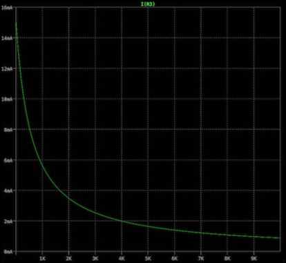
Note: plots produced by LTSpice IV (Macintosh) using a 30 mA Nichia LED model.
And that’s the problem: LEDs aren’t going to react to linearly increased resistance in a linear manner. This solution will work, but it won’t be ideal. You can get a fairly wide range of intensities, as long as you don’t mind only using about 1/3 of the pots range, or you can use a smaller pot and get more control, but with a fairly bright minimum setting.
Parallel Resistance
I ran across a suggestion on this thread of a way to improve the intensity control by putting a large resistor in parallel with the LED. Adapted for my 12V circuit, the following diagram is what it looks like. And it will make the control more linear, basically by sharpening the curve (it doesn’t look sharper in the plot below, but that’s because of the change of scale; it really is closer to the two axis, with a sharper curve at the bottom left). As you turn up the control, intensity drops faster than it would have with the earlier circuit. However it does this at the expense of siphoning off some of the current, so you never get to full intensity.
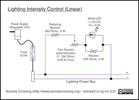
The theory is that as the voltage drops, the LED’s “dynamic resistance” increases, and putting a resistor in parallel will suck off some of the voltage. And yes, it will. This means the light will get dimmer faster. The resistor size needs to be “tuned” somewhat to match the LED characteristics, and I found that it needed to be much smaller than in the original, at least for LEDs I was looking at and a 12V source. I switched to a 1 KOhm, rather than 22 KOhm, resistor. The drawback is that this all happens in a relatively short range of resistance changes (and making the bypass larger doesn’t help). So, if you can find a 2K Ohm pot, it’s going to make a good control, but you can’t really use this well with a 10K pot, as you’ll only be using about 20% of its range.
Here’s a SPICE model plot showing the pot going from zero to 2K Ohms. The green curve is the current through the LED as in the previous example. The blue line is the current through the bypass resistor.
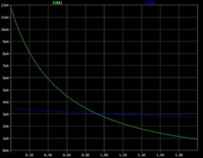
Notice that the green curve is starting at 11.75 mA here, as opposed to about 14.5 mA in the previous example (the 20 mA LEDs never quite get to 20 mA because the 560 Ohm resistor is oversized for safety). We’ve given up about 14% of the LEDs potential brightness to gain linearity. This might not be a bad choice, particularly with very bright LEDs. And you can tune it some by increasing the bypass resistor (which gains more top-end, at the expense of less linearity).
This might not be a bad choice, if you can find the needed parts and want to put in the time to choose just the right values, and assuming you don’t mind losing some of the potential brightness of the LED. It’s not an ideal choice though.
Transistor Control
Another way to control this is to use the POT to control a transistor, which itself handles the control of the LED power. The advantage here is that the voltage changes linearly with the rotation of the POT, since it’s not dependent on a current x resistance product. The basic circuit used for this is described on this page, and provides a constant current through the LED based on the voltage applied to the base (side) of the transistor. Adapting this to provide a variable current simply requires adjusting the resistance in the connection to the base, and for that we use a potentiometer (this time really used as a potentiometer, not a rheostat).
Adapting this to a variable current under control isn’t hard, but it does require understanding the needed voltage on the control line. You can find a lot of diagrams for this kind of control used with microprocessor pins online, since those have a fairly precisely specified voltage, but I couldn’t turn up any that used a potentiometer. The same principles apply, however. It’s just a bit complicated to work out the details, and I couldn’t find any simple formulas for calculating things, so I had to depend on a lot of simulation of model circuits to work out the rough values. Real circuits will need to be tested for specific hardware, as models often aren’t exact.
First, let’s start with the basic circuit. Current flows through this in three paths. The Green path is constant, set by Ohms law based on the sum of R1 and R2, and since that sum is going to be large, very little current will actually flow here, around a milliamp, less if we use a big pot or a lower supply voltage. The red path also has very little current flow, because it’s limited by the transistor as long as the voltage on the base contact (VB, the base voltage) remains below a threshold.
It’s the voltage thresholds that are problematic. For a transistor to work it must be kept in its “active” region, meaning that the voltage at the collector (top as shown here) must always be higher than the voltage at the base (left side), and in turn the voltage at the base needs to be higher than the voltage at the emitter (bottom). Collector and emitter are fairly easy; that happens as a consequence of current flow from top to bottom here. But we need to balance the control line connected to the base in between the two.
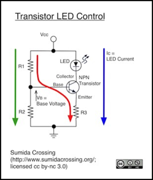
Voltage at the collector is controlled by the LED. This will be some value less than the source voltage, controlled by the LEDs forward voltage. So if the source is 12 volts, and Vf is 3.3 volts, this will be 8.7 volts, but the specific voltage depends on the LED. The emitter voltage will be some value less than this. When the transistor is active, that value is about 0.6 Volts (or a bit more) less than the base, so as long as we keep the base below the collector is should work.
Finally the blue arrow on the right shows the current flow through the LED, which drains to ground through R3. As long as the transistor is in “active” mode the driving voltage will be the source voltage less about 0.6 to 0.7 V. There’s a problem though: to keep the transistor active, we have to drop the voltage at the base below the voltage at the collector, using a much smaller current (through R1 and R3), and we have to keep that current in the zone where the amplification factor of the transistor (hfe or “beta”), which is usually around 100, both keeps the current through the transistor below its maximum and gives us a good range of variation. That’s not impossible, but it is hard.
Two things to recognize: while R1+R2 looks like a potentiometer it’s really a voltage-divider circuit. There must always be a fairly large value of R1 at a minimum, to keep the voltage at the base down. And it turns out that R2 can be zero (I’m not sure why, but the circuit works). So if we treat R1 as a fixed resistance to cause the needed drop, and R2 as variable (a pot), we can make a working circuit.
R3 plays an important role in setting the range for the current. As a general rule, R1 needs to be fairly large (but the exact value depends on the source voltage, and must be above a limit, but not too much above it), while R3 needs to be small, but not too small.
Caution: if R1 isn’t there, or is too small, the transistor will go into “saturation” and act as a short from emitter to collector. Given the small size of R3, voltage across the LED will exceed the limits of the LED and failure (permanent, LED-damaging, failure) will result.
I’ve come up with two circuits, based on modeling in SPICE (a whole lot of modeling). They’re really the same circuit, except for the chosen values of the resistances. These are somewhat tuned to the characteristics of the LED (Vf = 3.2, I=30mA). Current through the control line (red line above going through the transistor base) is going to be very small due to the amplification of the transistor, as long as we stay in the proper voltage and current range for safe operation of the LED. And current through the pot to ground (green path above) is defined by Ohms law and will be just a few milliwatts: both R1 and the pot will handle very little power, much less than typical ratings for even small trim pots. R3 depends on the current through the LED (blue line, plus a tiny bit from the red transistor control line). In some 12V cases R3 will need to be 1/2 W, but for a 5V supply it can be a 1/4 W resistor.
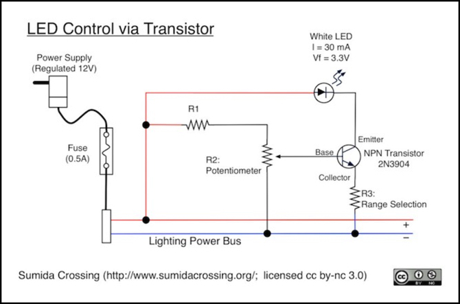
For a 5V source, R1 needs to be at least 18K for a 10K pot (10K does turn out to be a good size for the pot, although slightly larger, 20K - 30K, might work if you adjusted R1 and R3). For a 30 mA LED, R3 needs to be around 15 Ohms. For a 20 mA LED, it should be 30 Ohms or larger. For a 40 mA LED, you might be able to get a bit below 10 Ohms, but you’d need to measure current through the LED to be sure it was safe since I couldn’t model that.
For a 12V source, the problem is that you have to drop so much power in R1 that you lose some of your adjustment range. Thus, it’s better to use a native 5V source here. With 12V (and one LED; this isn’t going to work for two in series), you need to use a 100K pot and R1 needs to be 85k. R3 should be at least 39 Ohms for a 30 mA LED, and a minimum of 150 Ohms for a 20 mA limit.
R3 can be slightly oversized to reduce the top end, but you don’t want to do too much of that as it also reduces the adjustment range. I’d recommend using precision resistors for R3 (e.g., 2% or similar).
The transistor also matters, but the one I’m using is a 2N3094 NPN model, mostly because the specs are in the right ballpark and I found them in bulk at the local electronics store, but it’s a fairly common transistor and I had a SPICE model for it. These are rated for 6 volts Base to Emitter (and 40V Collector to Emitter), so they’ll be safe for what I’m doing with them.
The following graph shows the SPICE simulation of the 5 V version of the circuit as the pot is adjusted from 0 to 10K. This used R3 = 15 Ohms for a 30 mA LED.
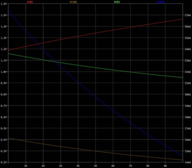
The red, green and orange lines show the transistor voltages: as long as green remains between the other two, as it does here, we’re operating in the correct zone. The blue line, read against the amperage scale on the right, shows the current through the LED, from a maximum just below its rated current, down to a bit less than half that with the pot turned all the way up. This was the widest adjustment range I was able to get.
Transistor Control II
A somewhat more complicated circuit, which doesn’t really fit the “simple” requirement if you’re doing just one circuit, fixes the transistor approach by using a low-voltage regulator to produce the base voltage, rather than a resistor. Because this provides a fixed voltage, it allows for more control. This approach can also be used with a 12V source, although it’s not quite as good of a control at that voltage. I should note that I haven’t actually built this circuit; it’s been modeled in SPICE, but that’s all.
There are plenty of low-voltage regulators, but not all can operate with sub-milliamp output currents. The one I’ve used here appears to be able to do so from its data sheet, but I’m a little skeptical. This is a fixed-voltage version of the regulator, to avoid additional feedback circuity needed with the variable-voltage versions. It still requires adding a multi-pin package to the circuit, plus two capacitors (required by the regulator). A third capacitor as a power reservoir may also be desirable, although in my modeling it wasn’t necessary.
In addition R1 changes to be 1,500 Ohms for a 5V source. The rest of the circuit is identical to the 5V transistor circuit. More on this below.
Note: one way to spread the cost of the regulator is to put several LED circuits on one control board. They can all share the regulator and its capacitors (each will need its own R1 and pot). Since the regulator can put out hundreds of milliamps, and each LED only uses a few, you could do this for tens of LED controllers quite easily, if you wanted to have a lighting control panel for a set of multiple buildings.
The following SPICE simulation shows the larger operating range this enables (5V version of the circuit):

As you can see, this allows adjusting the LED from 30 mA down to around 1 mA (by which time it will have gone dark). While the circuit is less linear at the low end of it’s range than the previous one, this is the portion of the range the previous circuit couldn’t provide.
The downside of this circuit, aside from added complexity, is that the selected rectifier (an LT3021-1.5 fixed-output device) costs about US$4.50 in single quantity, adding significantly to the cost. As noted above, you can spread that over multiple control circuits, so for larger systems the added cost and complexity are minor issues.
An advantage with this circuit is that not only is there good control over the LED, but since the regulator can operate on higher input voltages, it can work with a 12V lighting power bus. Using 12V for lighting power allows multiple LEDs to be driven off one feed when intensity control isn’t required. There will be some extra loss as heat, but that’s negligible at the currents being handled, unless you chain a whole lot of LED control circuits off the regulator.
Using this for 12V the resistor values change. R1 becomes 4200 Ohms (minimum) and R3 becomes 250 Ohms.
On a 12V supply, you can operate two LEDs (not three). R3 has to be roughly half the value (120 Ohms for the 30 mA LED) and R1 increases to 14,200 Ohms minimum. There’s a complex relationship between the two. If you change R3, the needed value of R1 will shift. I suspect it has a simple root in Ohms law governing the control current (red path), but I haven’t determined just what that would be. It’s easy enough to derive though: just build a circuit without R1 and turn up the pot until the base voltage measures below the emitter voltage, and then unplug the pot and measure it’s resistance: that’s the needed value of R1. If you never get to a good value, throw in a 5K R1 and repeat, and the pot value plus 5K will be what is needed for R1.
The 12V circuit has reduced range: you can only get the pair of LEDs down to about 19 mA. This may not be adequate, but could be addressed by increasing R3 to shift the range lower.
