


Prototype Couplers
One detail that is often overlooked on trains, at least by those less familiar with them, is the mechanism used to connect two cars together, known generally as a “coupler”. While the coupler used for freight cars in the U.S. and many other places (the Janney coupler) and its many variations is widely used, there are numerous other kinds. Most common for passenger vehicles are various “tight coupling” mechanisms, also known as “multi-function couplers” because they combine physical connections between cars with automatic connection of brake, power, and control lines as well.
Janney or Knuckle Coupler
The Janney coupler (known in the U.S. as the AAR coupler or “knuckle” coupler), a design originating in 1873, is and has been used on freight cars and locomotives in Japan since the 1920s. A large number of designs exist, and some models can support up to 32,000 pounds (per Wikipedia).

AAR Coupler (2006)
Photographer: Old Sarge
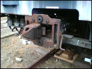
Tight or Close Automatic Coupler (密着自動連結器)
A variation on the Janney coupler used for some high-speed freight. This makes an automatic connection of the brake line when cars are coupled, if I’m reading the Japanese Wikipedia page correctly. This version also appears to make a firmer connection than an ordinary knuckle coupler.

EF65 Tight Coupler with air tubes (2011)
Photographer: Rs1421
Scharfenberg
One of the earliest tight coupling mechanisms was the Scharfenberg coupler, (developed in 1903) which is still widely used. A true Scharfenberg is similar to the Thomlinson and Shibata couplers described below, but has a circular point that rotates when engaging the other coupler. It’s most serious problem is that it’s not very strong, limited to about 1,000 tons, and thus only suitable for slower-speed passenger trains (not high-speed trains like the Shinkansen, and definitely not freight trains).
Also, while the mechanical part of the coupler is standardized, the associated electrical connections may vary. Note the two different locations of the electrical connections in the photos below (the gray shields with the lightning-bolt symbols rotate away to expose the electrical connectors).


Two examples of Scharfenberg couplers: British Northern Rail (left), and German ICE (right) (both 2006)
Photographers: Chris McKenna (Thryduulf), and “Robbie aka Zoqaeski” (right)
Although the Scharfenberg itself does not appear to be used on any Japanese trains, many similar coupler are used. And the name Scharfenberg appears to be used, at least informally, to describe this class of coupler.
Tight Coupler for Shinkansen (新幹線用密着連結器)
The rotary tight-lock couplers used on the Shinkansen (and made by Sumitomo Metals) are somewhat similar in design to the Scharfenberg, although described by the Japanese Wikipedia as a variation of the Shibata design. These were developed for the 1964 introduction of the first Shinkansen.

Shinkansen Coupler at Fukushima Station (2007)
Photographer: Tamikiku
Thomlinson (or Tomlinson)
The Thomlinson coupler was another kind of tight coupler, supposedly developed originally in the U.S. in 1910 by the Ohio Brass Company (and widely used on Interurbans, by report). However, the October 27, 1905 issue of Railway Age (Vol. 40, pg 544) lists a “Tomlinson automatic radial car coupler” made by the Tomlinson company of Chicago, Ill. Additionally, U.S. Patent 1,567,474 was issued to Charles H. Tomlinson in 1925 for an “electric coupler”. It’s unclear if this was related, although the images in the patent do not match diagrams I’ve seen of the Thomlinson coupler.
It was advertised in 1921 (pg. 200, EMF Electrical Yearbook, First Annual Edition, Electrical Trade Publishing Co., Chicago, Ill.) as being for “electric railway, mine and industrial cars”, and could couple pneumatic lines and optionally electric lines. The Thomlinson was introduced to Japan prior to World War II. According to the Japanese wikipedia, the Thomlinson is used in Japan by JR West as well as the Tokyo Metro Marunouchi and Ginza line trains, except for some later trains. The Tokyo Metro version has a brake pipe above and below the coupler. This coupler is smaller than the Shibata.
Photos I have found look similar to the Shibata (with square profile points rather than circular ones like the Scharfenberg). One advantage of the Thomlinson was that it could couple to other standard Interurban couplers, including the Brill, Van Dorn and Standard Pocket couplers. The photo below doesn’t quite match diagrams I’ve seen of American Thomlinson couplers, but it is referenced for the section of the Japanese Wikipedia page describing the Thomlinson.

A “Tomlinson” coupler on the Hitachi Railroad (2005)
Photographer: Tamikiku
Shibata
JR has widely standardized on the Shibata coupler (柴田 or 柴田式) also called the “tight coupler Shibata expression” (柴田式密着連結器), often mistakenly or generically called a Scharfenberg coupler. This coupler was developed by a Japanese Railway engineer, Mamoru Shibata (柴田衛) in the 1930‘s for use with trains needing electrical connections. The Shibata coupler is larger than the Thomlinson coupler.

Shibata Coupler at JR East Kamakura Rolling Stock Center (2004), and Close up (2006)
Photographer: Tamikiku (both)
Note: link for left photo original no longer works.
