


Train Power Requirements
Electrical power is a function of voltage and current (literally: Power in Watts is equal to the current in Amps multiplied by the voltage in Volts, or P=IV). Power for model trains and accessories is typically measured in thousandths of an Amp, or milliAmps (mA) (with an assumed voltage) or in thousandths of a Watt, or milliWatt (mW).
Note: one milliAmp of current at 12 volts provides 12 milliWatts of electrical power (that’s P=IV again).
What really matters in a model train is the torque produced by the motor (which varies with current) and the power to move a train (“power in rotational motion”, which is at it’s maximum at about half the full unloaded speed). Torque is used to overcome friction, and is particularly important when starting a stopped train. And the pulling power derives from the torque of the motor and its ability to turn the motor (the “power in rotational motion” bit). Torque is based on the design of the motor, and its application depends on both that and the geartrain connecting the motor to the wheels. But ultimately it is related to the current through the motor, which is varied by changing the voltage.
The relationship is fairly complex, but it is usually simplified and expressed as a need for electrical power (which is based on current and voltage, as described above).
A model train requires electrical power for three things:
• The motor that makes it move,
• Accessories, typically headlights, tail lights, and interior lighting, but also things like automatic couplers,
• and sound systems.
That last isn’t yet typical in Japanese N-Scale, although sound has been taking much of the rest of the world by storm.
Motors
Motors have two significant measurements: the power normally drawn by the motor, and the worst-case power drawn when the motor is just starting, or is held motionless (stalled). Most model trains use DC motors with brushes (some use brushless motors, but these require specialized control circuitry and are less common). There are a number of variations in the specific motors as well (e.g., Five Pole vs Three Pole), but they are all similar in that they turn at greater speeds with higher voltage.
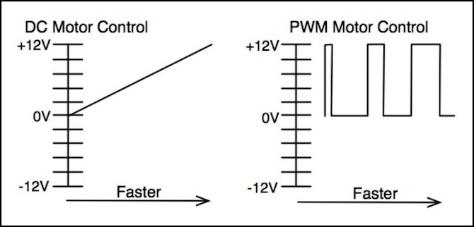
DC power packs use this directly to control the motor speed (and thus train speed) using a DC track voltage that varies from zero (stopped) to around 16 Volts (N-scale is often said to be limited to 12-volts, but many people use HO power packs, which typically produce 16 volts at maximum throttle, for N-Scale trains).
DCC decoders could use variable DC outputs to control the motor, but more typically they use “Pulse Width Modulation” (PWM) outputs. PWM uses a constant voltage, which is on for greater or lesser intervals, to control motor speed. In this, it is the average voltage that is used to compute the power (i.e., the average over some interval where the voltage is at zero for a fraction of that time, and at maximum for the rest of the time).
Power used by a DC motor is thus based on the voltage (or average voltage in the case of PWM) and the current supplied to the motor. With DCC, there is additional power lost in the decoder and it is harder to measure the voltage and current supplied to the motor, but otherwise the measurements are performed similarly to the way a DC motor is used. It is easiest to measure motor power using a non-pulsed DC power pack and a volt-meter and ammeter, multiplying the two values together. See the Power Pack Testing page for what this means. However, with DCC systems you can measure the total power to the train (assuming it isn’t using any for other purposes), which will be the sum of the DCC decoder requirements and the motor power.
Running Motor Power
When a train is moving at a constant speed over level track, the power needed will be a constant amount required to overcome friction and keep the train moving. At greater speeds there is greater friction, so more power is needed.
But at the same time, a motor that is turning generates a backwards voltage, called Back Electromotive Force (Back EMF, or Counter EMF) that reduces the current through the motor, and thus reduces the power. With a constant load, Back EMF is higher as motor speed increases, and this to some extent counter-acts the power needed to make the motor run faster. However, if the motor is working against an increased load (e.g., if the train is moving uphill or is pulling more cars and thus working against greater friction), the Back EMF will drop for a constant speed.
Some DCC decoders measure Back EMF to estimate the actual motor speed, and adjust their output to maintain a constant rate regardless of load (see the Back EMF page for more about this). This also means the power requirements measured on a locomotive alone will not be the same as for the locomotive pulling a string of cars (which adds to the friction, and thus increases the load on the motor).
Motor power is thus best measured on actual track with the size train that is expected to normally be used, rather than being measured on a “rolling road” or even a test track with no attached train.
Back-EMF can compensate for a poor motor (one with fewer poles) to an extent, but it does so only if the motor is already turning. It won’t help a motor with poor low-speed performance start at a lower speed, although it may help it run more smoothly once it’s moving.
Many DCC decoders use pulse-width modulation (PWM) to drive the motor with a stream of pulses of variable-duration at track voltage (or close to it). This provides for increased torque at low speeds, and can improve low-speed performance. However, this can also produce noise since the pulses cause the motor to vibrate. So-called “supersonic” DCC decoders use pulses at a frequency high enough to be difficult to hear (not always supersonic: TCS is said to use 16,125 Hz, which is within the hearing range of most people, although sensitivity to such frequencies declines with age, so it may be “supersonic” for many modelers).
Measuring Stall Current
The stall current is the current through the motor when it is producing zero back EMF, which happens when it is working against maximum load, or when it is not moving (and is effectively a short circuit limited only by the internal resistance of the motor wiring). This is the maximum current the motor can draw. Stall current is important when selecting a DCC decoder (see the DCC Decoders page for more on that topic), and a (non-pulsed) DC Power pack is handy for is measuring the stall current of the motor since it eliminates any extraneous electronics.
The way to do this is to hook an ammeter up in series between a DC power pack and a section of track. I’ve used the RRampMeter for this. One problem with this, however, is that pulsed power confuses the RRampMeter, and causes it to fail to read the current. So a cheap DC power pack that doesn’t provide pulsed power is, ironically, better than an expensive one for this purpose. If you have a pulsed power pack, you may be able to use a multimeter with an AC current scale with pulsed power, although I’m not sure how accurate this would be. As noted on the Power Pack Testing page, the Kato DC Power Pack (at leas the model sold by Kato USA) does produce a form of pulsed power, so it’s not the best choice for this.
Note: The RRampMeter can measure DC current, but the meter is only active with one polarity (unless you buy the battery-operated model), so if it’s dark, reverse the direction switch on the power pack. This caused me a few minutes of confusion.
To measure stall current simply press the locomotive down onto the track hard enough that the wheels can’t turn and turn the throttle up to full, then measure the current being drawn from the power pack with an ammeter. But be careful, as that may involve enough force to damage detail parts, and it puts more strain on the drivetrain.
Another method you can used with some models is to open the chassis, place the locomotive on the track, grab the flywheel or some other part of the locomotive’s drive train to keep it from turning. But this won’t work with most Japanese models, as their drivetrain tends to be hidden inside the floor or weight.
My Kato DE10 for example has the motor inside the weight, so I did it that hard way:
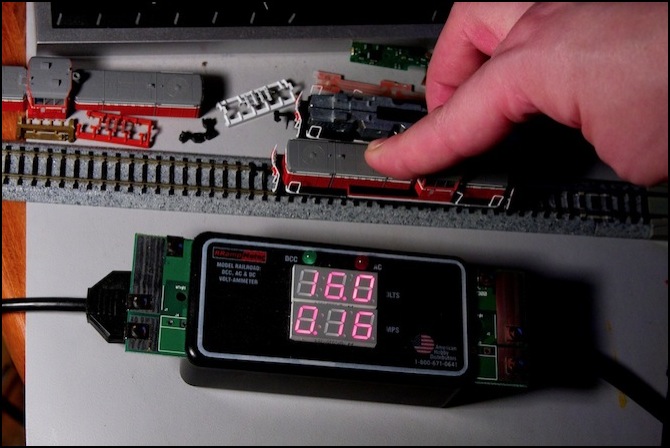
Kato DE10 Stalled with 0.16 Amp (160 mA) Stall Current @ 16.0 V DC
While this photo shows 160 mA, the current varies and I measured a peak stall current of 230 mA. It also shows that the MRC power pack that outputs 19.1 V DC with no load is producing 16.0 V DC under the full load of the locomotive. Which is what it should do as an HO power pack.
Note: some DC power packs put out a very high maximum voltage (sometimes over 20V). If using one of these to test stall current, setting the throttle to an intermediate speed with a lower voltage similar to that which will be used on the DCC track is a good idea.
Stall current is proportional to voltage, so if you want to be sure your decoder will be safe on a higher-voltage system, but don’t want to test the loco at that voltage for fear of damaging it, check it at another voltage, divide by that voltage and multiply by the target voltage. So, for example, if a loco has a stall current of 160 mA at 6 volts, and I want to be sure I can use it on an 18-volt DCC system (probably not a good idea for an N-scale loco, but it’s a safely larger number to use for a worst-case), take 160, divide by 6 and multiply by 18 to get 480 mA. Thus a 500 mA decoder would be safe on this loco (those are the actual numbers for the Atlas B23 I use for DC testing, by the way).
Stall Current and Normal Current
When a locomotive is operating normally (i.e., pulling a train) it draws something less than stall current. Knowing what this is can be helpful for designing a large layout with many operating trains, as it's unlikely they'll all be stalled.
The following table summarizes some current measurements I reported in a thread on the JNS Forum. Note that I'm abstracting the original a bit here; see the thread for all of the detail. Also, "NM" means no measurement was made for that speed range. As you can see, the Kato DE10 that drew 160 mA of stall current uses less than half that at normal operating speeds (without a load, although power use with a small set of cars increases very little, perhaps 5 mA or less for ten cars).
Power Draw:
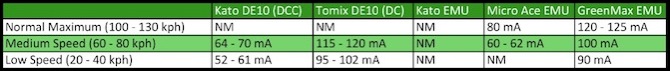
Note that the above numbers are for the complete train, but the specific trains tested did not have lighting units installed. Power requirements will increase by a small amount for LED lighting, and a much larger amount for bulb lighting (a ten car train using bulbs could use as much as 600 mA just for lighting). All tests were on DC (the "Kato DCC" unit was equipped with a DC-compatible DCC decoder).
References
The following provide additional information and more depth on topics related to powering model trains.
DC Motors: Coercing Top Performance with AC Drive Signals, by Bruce A. Metcalf, a paper describing DC permanent-magnet motors and control systems, and specifically the NMRA-standard waveform desired (and the fact that most DCC decoders today deviate from this standard).
Micromo.com - a website for a manufacturer of small DC motors, with a number of informational pages. In particular, this page describing brush-type DC motors is particularly informative. One interesting recommendation is to twist the motor leads so that electromagnetic interference (EMI) will be minimized. This could apply between the DCC decoder and motor, as the pulse-width modulation used may generate EMI (although it’s unlikely to be enough to affect anything).
Small DC Motor Tips - a page describing DC motors for model railroad use. Although orientated at large-scale motors (garden railways), much of the description is general.
