


DCC Basics: Motor Control
DC motors are controlled by varying the voltage and polarity of the DC power connected to them. In a simple DC power-pack a rheostat is used to provide a voltage to the track that varies from zero volts to the power pack’s maximum, which is often around 16 Volts. A simple switch is used to swap the positive and negative outputs to change the polarity (and thus the direction the motor turns). This tends to waste a lot of power as heat because a rheostat is a resistor and resistors convert power to heat, but since that’s happening inside the power pack, and “a lot” isn’t really all that much at these voltages, that’s acceptable.
DCC decoders need to take a constant-voltage AC input from the rails, and control a DC motor somehow. Even if they could use a rheostat or transistor the way a power pack does, wasting power as heat inside a plastic model is more problematic. The technique normally used instead is called Pulse-Width Modulation, and it’s a fairly simple and commonplace, and efficient, method of controlling DC motors from a digital controller. The same technique is used in many other applications outside of model railroading, and most motors today are designed to work well with PWM (this may not be strictly true of motors made prior to the 1980s, although often those will work without undue wear on the brushes, which is the main risk).
PWM is very straightforward: the digital signal on the rails, which is a form of AC, is first converted to DC in a rectifier, providing a constant DC voltage, and the DC is then sent to the motor through a controller. The controller doesn’t just send the voltage constantly though, instead it can be turned on and off very quickly. If it’s mostly on, the motor is getting near full voltage, if the interruptions are more frequent or longer, and it’s mostly off, the motor is getting very little average voltage, even though the peak voltage is still the full DC voltage (perhaps 16V). The polarity can also be reversed in a manner similar to the power pack, and this too is a function of the motor controller. And because it works by turning off the power with a switch, rather than throwing it away in a resistor, it’s not wasting power or producing excessive heat.
DCC motor control is fundamentally a “digital” form of motor control. Digital motor control could be used in other control systems (like a conventional “power pack”), but commonly those use analog (i.e., DC) motor control.
The rest of this pages gets into the technical details of this, none of which you need to know to run trains with DCC. But I’m curious, and like to know what’s going on inside things.
DC Motor Design
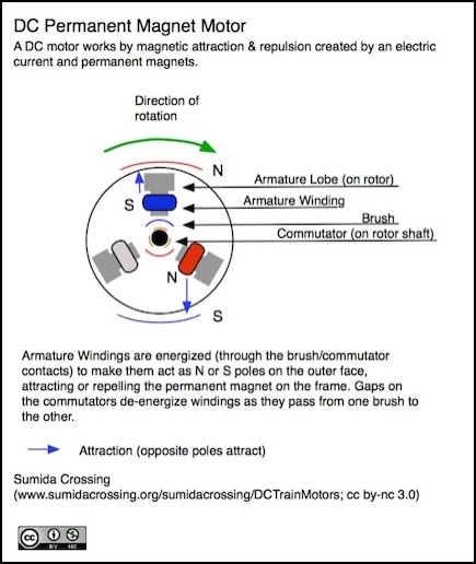
Model trains typically use “brushed permanent-magnet DC motors”, meaning motors that uses brushes to energize windings (via a “commutator” contact) on the moving part of the motor (the armature) and create a magnetic field that acts against that of a permanent magnet mounted to the stationary frame of the motor. In this kind of motor, the current in the winding has to reverse as the winding moves from when it is approaching the magnet’s “north” pole to when it is approaching the magnet’s “south” pole. This is achieved by putting a brush on each side of the motor, and arranging this so that the “commutator” for one end of the winding will contact one brush for roughly half the cycle, and the other brush for the other half of the time (and vice versa for the commutator on the other end of the winding). To avoid short circuits there needs to be a gap where it contacts neither. For more details on such motors, see my DC Train Motors page.
In a typical motor, power to an individual armature winding will be positive for half of a rotation of the armature, and negative for the other half. The actual “on” percentage will be less than half, but probably not much less, due to gaps between the commutator pads. During the half-rotation that the winding is in one polarity there will be a constant magnetic field generated by the winding. When it switches polarity at the end, there’s a period where the old magnetic field dies down and the new one (in the opposite direction) establishes itself. This happens very quickly, with the complete changeover taking roughly a quarter a millisecond for typical N-scale motors, and perhaps three-quarters of a millisecond for an HO motor.
The length the field remains on depends on the speed of the motor. At full speed, a motor may be turning at 14,000 RPM, or roughly 4.2 milliseconds per rotation. At low speed a rotation could last close to 100 milliseconds. Which means that at the fastest speed the armature is changing polarities roughly every 2.1 milliseconds.
The above is true of a motor on simple DC power, and is based on the physical structure of the motor. With DCC it doesn’t change. What does change is that during part of the interval where the brush is touching the commutator and electricity could flow (and would flow with normal DC), there may be no electricity flowing because the motor controller has turned it off. But simply turning the voltage off doesn’t turn the magnetic field off; as noted it takes time to die down. If the pulses come close enough together, the field will remain at mostly the same level, varying only slightly as pulses come and go. We’ll come back to this important point below.
Motor Controller and PWM
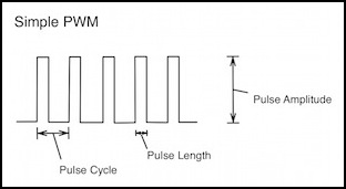
With DCC, the motor’s speed and direction must be controlled by a digital processor, working with the constant-voltage power supplied by the track (the DCC on the track is alternating current, but in a roughly square wave, so when rectified to DC it produces a constant DC voltage). The most efficient way to do this is through pulse-wave modulation, where power is switched on and off quickly to create “pulses” of full-voltage power (the “pulse amplitude” is equal to the rectified DCC voltage). These pulses repeat on a regular basis (the “pulse cycle”) and the longer the pulse, the higher the average voltage provided. And it’s the average voltage that defines the speed with which the motor turns.
For more about PWM, see the PWM page.
PWM
The way the decoder creates these pulses is to use a set of four transistors acting as switches. In the diagram below, the track voltage is rectified and fed to the left (positive) and right (negative) sides of a structure known as an “H bridge” (look at it sideways to see the “H” shape). When switch 3 and 2 are on (as shown), the motor will rotate in one direction, when switches 1 and 4 are on, the motor will rotate in the other direction, and when all four switches are off, no voltage is being delivered (the gap between pulses).
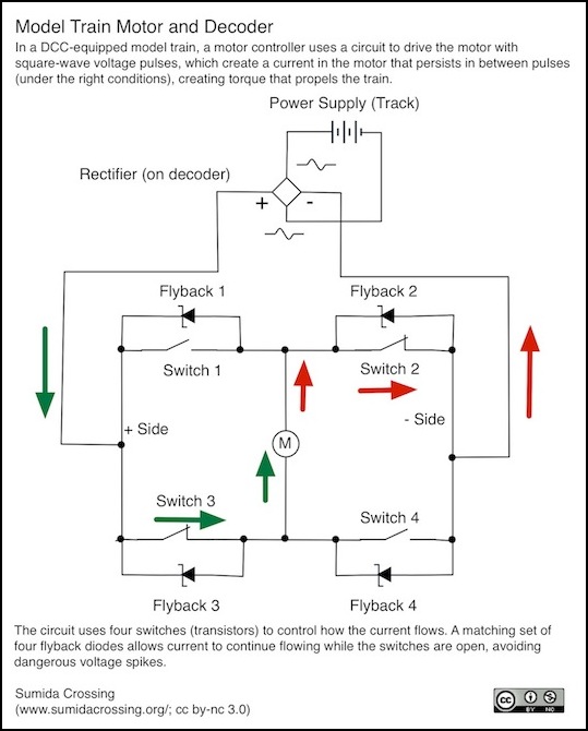
But there is a bit more going on. What the voltage pulses really do is create a current through the motor. While voltage produces speed, current produces torque, which is the energy needed to move the train. And because the motor’s wiring is an electromagnet (which is a form of inductor), once the current starts flowing it doesn’t stop immediately when the voltage goes away. To permit the current to continue flowing when the switch (which is a transistor) is off, the circuit will have “Flyback Diodes” that permit the current to bypass the open switches (without this, the energy stored in the inductor would build up a damaging level of voltage between pulses).
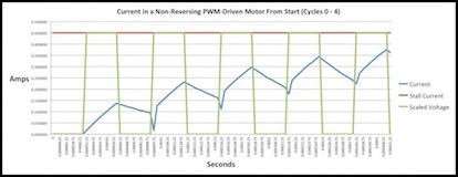
Typical Current (blue) due to voltage pulses (green)
If the pulses come close enough together, the current never quite stops, and the end result is more even production of torque and smoother operation of the train. Of course as the armature turns, eventually the current changes direction, the pulses now operating in the other polarity, and the current slows and reverses direction. This happens fairly quickly, so the energy wasted when the current is being reversed is minimized. At typical operating speeds, a “supersonic” decoder is going to produce at least ten and possibly thousands of pulses before the armature can reverse polarity.
Motor Operation
The motor in the train operating on DCC is thus part of a more complex system, the operation of which can be modified to an extent by how the DCC decoder is configured. This has a number of different effects, and often more than one way to emphasize one attribute over another, or to chose how the motor will behave under different conditions.
Motor Torque
Torque is the rotational force produced by a motor, a measure of the power available to move the train, overcoming friction and pulling loads up grades. More torque means longer trains can be pulled, or steeper grades climbed for the same size train, or higher speeds can be reached. Torque is highest when the motor is stalled (“stall torque”) and declines linearly with rotation speed until it reaches zero at the unloaded maximum rotational speed (when all power is being used to overcome internal friction and back-EMF). In practice, the load on the motor will define the maximum speed; more load, and the motor runs out of power to move the train against it’s own drag at a lower speed. If torque is reduced, then the train will have a lower maximum speed, and in fact a lower speed for a given voltage compared to the same motor with less load.
Fundamentally torque depends on the design of the motor and drivetrain, in particular on the electrical power supplied to the motor (voltage times current) and the gear ratio of the drive train (a higher ratio means a lower top speed but more torque for pulling loads).
With PWM another factor comes into play. Fundamentally, a DC motor works by creating magnetic fields in the windings of the motors armature (the moving part in the middle) that react against the fixed magnet on the outside of the motor. Electric current produces a magnetic field, but magnetic fields have a tendency to persist for a short time once created. Ideally a continuous current would be used, which requires a continuous voltage. In a DC train, that’s exactly what is done.
But with DCC, PWM is used, meaning that instead of continuous power, there are pulses of power (pulses of voltage, which create pulses of current). Because magnetic fields tend to persist, this works. But because magnetic fields also tend to build up slowly rather than instantaneously, longer pulses are better than short ones. As PWM frequency gets higher, pulses get shorter but more frequent. The same amount of power in the PWM pulses is less effective at building a magnetic field with short pulses as it would be with long ones. The effect is that higher frequency PWM produces less torque for the same available track voltage than lower frequency PWM, and this effect is magnified at lower speeds.
Note: strictly speaking, “power” in a motor is the product of torque and angular speed, and is maximized at the halfway point between full-load/no-speed and no-load/full-speed (at both of which points one factor is zero and hence power is zero). Meaning that a motor produces its maximum power when it’s turning at half its maximum unloaded speed. An interesting corollary of that is that since current is proportional to torque, not power, the motor will be drawing exactly half its stall current at the point of maximum power.
Train Speed Control
In a DCC system, the connection from the throttle controlled by the operator of a model train to the decoder is digital, and DCC defines the speed of a train as a “speed step” from zero (stopped) to 126 (100% speed). When the operator turns a throttle knob, the throttle converts this into a speed step and sends that to the decoder.
Although the motor controller chip on the DCC decoder deals with the motor in terms of a PWM pulse duration and the delay, the decoder deals entirely with a percentage of track voltage, typically expressed as a number from 0 to 255 (where 255 = 100%). This exactly fits in an 8-bit Configuration Variable (CV). Normally a decoder will have a speed table made of 28 CVs (it estimates the ones in between to create a table of 126 steps), although the table can be just three CVs (stop, middle, and full) from which it will calculate a full speed table.
The decoder looks up the received speed step in whatever it’s using for a speed table (set by the user or calculated), which contains the appropriate voltage level. So half throttle might be sent as speed step 63 (of 126, meaning 50%), and looking that up in a speed table might produce 50% motor voltage, which would be represented as 128 (out of 255) in the table. Of course the user could have decided that half throttle should produce 1/4 speed (or anything else) to allow for smaller changes at low throttle (and larger changes at high throttle), and programmed a number like 64 (out of 255, meaning 25%) in that cell of the table, but we’ll ignore that for this example.
Motor controller chips typically also represent the output voltage as a fraction using 256 steps, so the decoder could simply take the value from the table (128 in this example) and put it in the controllers voltage-control register to set the motor voltage. More often, manipulations will need to be done on the number (for improved slow-speed running or load compensation), and sometimes motor controllers use a larger number of steps in their control register (so voltage could be defined on a 0 - 511 or 0 - 1023 scale). Thus the usual result is that the decoder takes the value from the speed table (128), scales it to fit the controller (e.g., to 256 for a 0 - 511 scale) and then applies any modifications to it (such as changes due to BEMF and “dither”, or scaling from one of the Trim CVs), and ends up with a motor speed percentage (such as 76/128 or 152/256 or 608/1024, all of which mean 59% voltage).
It may also apply changes such as momentum (which are based on the Acceleration and Deceleration CVs). This would cause it to save the target speed (128 in this example), but set the motor to some speed between the current speed and the target speed for a time, then set it a bit higher (or lower depending on whether the throttle had been turned up or down) and repeat until it had gradually adjusted the motor to the desired speed step using the selected acceleration (or deceleration) rate.
One important consequence of this is that the speed of a train depends on the track voltage. If you set up a train to run at 100 scale mph at 100% throttle on a 13.8V Zephyr like mine using a speed table, and then take it to someone else’s layout that uses a 16V “HO” DCC command station, it’s going to run something closer to 116 scale mph (the actual speed will vary due to other issues like friction in the drive train, so that’s only approximate). On a 12V “N” DCC system, it will run at something closer to 87 scale mph. There’s no such thing as “absolute” speed with DCC, only fractions of track power.
PWM Frequency and Audibility
The frequency of the PWM cycle (what I’ll call the base frequency for reasons that will become clear in a bit) is controlled by how the decoder’s motor control circuitry is built, and to a limited extent can be altered by making changes to how it is set up by the CPU (this is why some decoders can let you turn off “supersonic” PWM). The choice of what this frequency should be is not a simple matter (I go into some of the issues on the PWM page).
But one important aspect is that each pulse makes the motor vibrate slightly, so the pulse frequency produces faint sound waves of the same frequency. Higher frequencies are harder to hear, making the motor less noisy. Lower frequencies are also bad for the motor: below a threshold they cause more heating of the motor, and too much of that can damage it.
Hearing loss happens progressively with age, making it harder to hear all sounds. But the effect is magnified at higher frequencies. It’s not so much that older people can’t hear higher frequencies, but that their (our) sensitivity to them drops, making it harder to hear quiet higher frequencies. A loud motor close up at 16 kHz is likely still audible to 50-year-old who couldn’t hear it ten feet away. Whereas an 18-year-old probably hears both equally well. So a decoder that’s “supersonic” at 16 kHz is likely still audible if you listen close (unless you have other hearing-loss problems), but put it in a body shell that damps the vibration (not all will do so) or stand back from it, and you may not hear it unless you are younger than the average model railroader.
Also, PWM isn’t necessarily just one frequency. In some throttles it is, and the “base frequency” is the only frequency. But in others, because the pulses are bunched into groups, the sound you hear will depend on the cycle over which those groups occur. This will be lower than the base frequency, and thus more audible. So “supersonic” is something of a misnomer, although the high-frequency PWM called “supersonic” does reduce the amount of nose that’s audible.
Low-Speed Compensation
When there’s no magnetic field in the armature a motor isn’t turning, and the friction of the motor and drive train is “static” friction, which is higher than the “dynamic” friction that comes into play once the motor and gears are turning. For these reasons, getting a stopped train started requires a little extra “oomph” that won’t be needed to keep it moving.
One common method to get a motor started is to briefly apply extra voltage when the decoder moves from speed step 0 (stopped) to speed step 1. This extra voltage comes in the form of holding the first pulse on longer. For example, a typical PWM pulse might be a multiple of 0.24 microseconds (corresponding to a decoder frequency of 16 kHz). This is extremely short. A motor at its slowest speed is probably turning at about 55 RPM. This means that each rotation lasts over 900 milliseconds, and there would be about 7,200 of those short pulses occurring in a single half-rotation to energize a winding. But because each is short, with a long gap between them, the magnetic field in the motor could be slow to build up. At its fastest (14,000 RPM) a half-rotation lasts just 72 microseconds, but at that speed the pulse would fill the interval (62.5 microseconds), even at 90% throttle it would be effectively continuous.
Note: at a decoder frequency of 1,000 Hz, each pulse would still be only 4 microseconds long, and there would be about 450 of them per half-cycle.
So by holding the pulse on longer, often several milliseconds, more energy is pumped into the motor to create the magnetic field. Once established, this controller can use ordinary pulses to keep the motor turning. The optional Kick Start CV (CV65) can define the “amount” of this kick, but since the NMRA didn’t define how it was used, a value of “2” on one manufacturer’s decoder may not work the same as a value of “2” on another’s.
TCS has replaced Kick Start on their decoders with “dither”, which is discussed in the Torque Compensation section below.
For a given motor and drive mechanism, a voltage of 1/255 of track voltage may not be enough to keep the motor turning, so it may be necessary to also set the Start Voltage (CV2) or Speed Step number 1 (CV67) to a value higher than 1. Which to use depends on the decoder, and whether you are using the basic speed table or the “28 Step” speed table (enabled by adding 16 to CV29, which sets bit 4). On most decoders, CV2 only applies with the basic table, but some decoders apparently also enable it with the 28-step table. CV67 only applies when the 28-step table is selected.
One more problem is torque (power). It takes more power to move a locomotive pulling a train, than to move just one locomotive. And it takes more power to pull a train up hill than to pull it on level track. For this reason the step 1 voltage may need to be higher than what it takes to keep just a locomotive moving. If you set up the loco alone on a test track, then put it on the layout with a train, you may be disappointed.
Torque Compensation
But there are decoder features that can help solve this problem. These go under different names from different vendors, and may reflect slightly different methods, but all of them share the same goal: to compensate for low torque, particularly at low speeds. There are two major types of this: the non-adaptive ones (often called “dither”, although Digitrax simply calls theirs “torque compensation”) and the adaptive method usually called “BEMF”. I’ll cover BEMF separately, so for now lets focus on the non-adaptive ones.
As the term implies, these are simple methods that don’t change what they’re doing based on how the motor behaves. You turn them on, and maybe set a configuration variable to tune it to work better with your motor, and it “just works”. What it’s basically doing is adjusting the way the pulses are provided to the motor at low speeds, to ensure that the magnetic field in the armature is stronger, at least some of the time, increasing the average force the motor is using without necessarily increasing the speed that it is turning.
I don’t actually know what “dither” does. This is an area I need to investigate.
Back Electromotive Force-Based Compensation
Electromotive Force (EMF) is another name for voltage, it’s basically the force that pushes electrons through a conductor. One characteristic of a motor is that it creates a voltage in the windings that opposes the voltage causing the motor to turn. This reverse voltage is known as back electromotive force (or BEMF). It basically subtracts from the driving voltage, reducing the current through the motor, and lowering the effective torque of the motor. The amount varies with the rotational speed of the motor, so a faster motor produces more BEMF and has less torque.
A neat trick with this is to briefly turn the voltage driving the motor off, and measure the current produced by the back EMF. Because the current isn’t produced immediately, it takes time (likely over a millisecond) to measure this current, so there is a fairly long measurement period required in comparison to the PWM frequency (which would normally be issuing tens of pulses per millisecond for a typical “supersonic” PWM frequency. But if this isn’t done often, the occasional lost power won’t be significant.
Once the current is measured, the speed of the motor can be estimated. And since speed is based on the applied voltage and the load on the motor, the load can be estimated (since the controller knows what voltage it is sending). Doing this dozens of times a second allows the motor controller to raise and lower voltage to compensate for changing load (e.g., going up and down grades, around curves, or across switches or crossings where the wheels encounter increased resistance.
All of this makes for a highly-responsive control mechanism (a “closed loop” control method) that can adapt to changing conditions to maintain the motor, and thus the train, at roughly the same speed. For more on this, see my BEMF page.
