River Crossing Terrain
After the basic scenery form and the number of foam layers had been defined, in February 2010 I turned my attention to the sweeping curve and bridges of the River Crossing scene. The key issue I needed to resolve here was how the “village” area would fit into the curve of the outer tracks. Would it be atop the upper layer of foam (2.75” or 7cm above table top) where the tracks needed to be, on the first layer of foam at 0.75” (1.9cm), or should I do something else? Related to this was the question of the station structure in the Urban Station scene, and how high the bridge into that needed to be, would it be at 2.75” or did I need to make it higher? I eventually decided that another half inch was needed there, and a Woodland Scenics incline was added to the curve to bring the track on that side up, so the bridge would be level into the station.
The bulk of the work described here took place in one weekend in February 2010, although planning had gone on for several weeks previously, and some of the finishing up took place over the next week or two after the work.
The Village Area
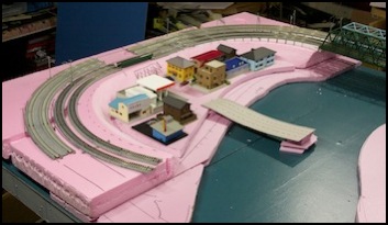
After cutting the two layers of foam for the village side of the river (only the lower layer was glued down) I did some tests to see how my initial idea of the village at the high level would look. This quickly convinced me that the buildings were too high above the river.
The Village: early placement test (January 2010)
Having decided I wanted it lower, I cut out the middle of the curve and shaped it to a rough slope (it would be reshaped a bit before I was done) and cut another layer of 0.75” foam to raise the village about the level of the riverside embankment. This more closely mirrors the land along the Sumida, which is up at the level of the top of the levee wall on the east side, roughly six meters (20 feet) above the water. My village was now at a scale 5.7m (~19 feet), a more reasonable-looking height.
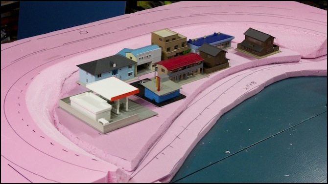
Village lowered to 1.75” (January 2010)
These weren’t the final set of buildings, or the final arrangement. I’d probably use most of them, but I have a larger collection of buildings from the old Kitchen Table Layout that I can pick and choose from; this was just to get a feel for how much I could fit in the space, and how it would look.
Foam Cutting
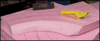
To get to the lower level, I needed to create an embankment by shaping the foam. My approach to using foam for scenery involves horizontal layers. Many books will show foam placed on edge and glued before being carved to shape, and that’s a good technique for making mountains. But I wanted layers of land at different heights, and was willing to live with multiples of 0.75” and 2.0” as my layering. First step (left below): rough carve the foam. Then (right) smooth and shape the foam using a Stanley Surform (a.k.a., “cheese grater”).
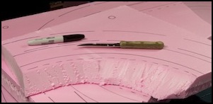
Carving the foam was, as expected, quite messy, producing an amazing amount of dust. The foam dust picks up a static charge when you rasp it off, so it sticks to anything and everything, turning the whole area pink. I wore old clothes and a respirator, and stopped periodically to vacuum myself, the floor, the foam, and anything nearby.
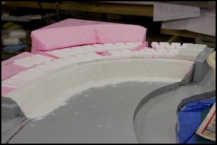
Shaping Terrain
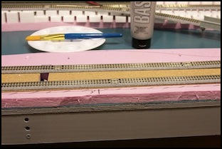
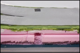
The corners were too flat, so I grabbed a couple of scraps and carved them into hillsides. The trenches carved into the top layer are for electrical wiring (leads from the track). These are placed to line up with the track joiners on both sides of the center. Cork and plaster-cloth will go above them, giving me a hidden channel to feed the wires through out to the edge of the table, where there’s a hole down to the underside.
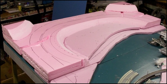
Carved Foam (February 2010)
After staring at it for a while, and checking the track placement one last time, I glued the 2-inch layer of foam to the lower layer using Woodland Scenics Foam Tack glue, added some weights to clamp it in place, and let it sit overnight. I didn’t yet glue down the two little hills or the sheet where the buildings will go.
As an aside, Foam Tack glue is reported to set in one hour (there’s a 15-minute “working time” where you can separate and move pieces). However, I’ve also read that it takes 24 hours to fully cure, and since it’s some kind of water-based adhesive, that seems reasonable to me. So I took care not to disturb it until it had at least a 12-hour setting time.
But in the morning, I woke up realizing that I’d made a mistake: no city planner in their right mind puts a bridge across a river this large just to reach ten small buildings. If there’s a bridge, then the street needs to continue. This also gave more reason for the gas station to be present, as those are typically found on through streets with more traffic. So, I needed to make an underpass under the tracks, and extend my four-lane (two each way) commercial avenue from the Urban Station scene across the bridge and through this scene. Which meant removing some of the foam I’d glued down the night before.
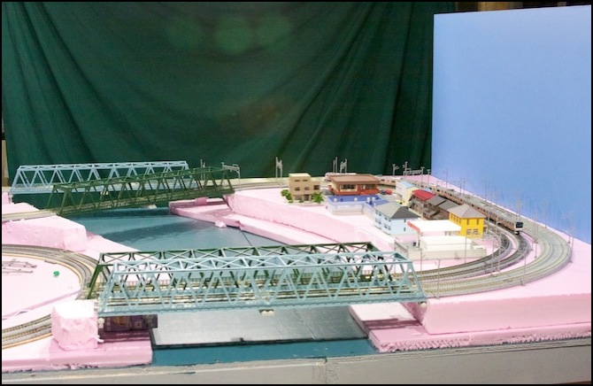
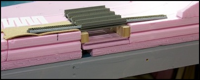
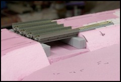
It also meant a trip to my local hobby store: I needed to decide what the track would use to bridge the street, and I didn’t have any 124mm bridges to test fit. My first thought had been to use the 186mm bridge, which I do have a couple of, but that’s quite long, and the street barely needs to be 80mm even if I include sidewalks. At 124mm, there is a single-track bridge, and it looks a bit better. But there’s also a single-track viaduct piece that looks reasonable as a ballasted-deck bridge (not perfect, but acceptable). Either would fit the same cutout, so I deferred that decision. I acquired some of each for testing purposes, and eventually settled on the viaduct.
Back went all of the buildings, along with a bit of cardboard marked to show the planned bridge, and after a bit of rearranging I had my wide avenue, and the bridges worked out. The photos below shows the 186mm bridges (left) and the 124mm model (right). Although I didn’t use the 124mm bridge here, I did use it for another road underpass on the Riverside Station scene.
Now I had the problem that I needed to cut the foam I’d just glued down a day before. Fortunately Foam Tack glue is easy to remove: after cutting through the 2-inch foam on both sides of the planned underpass with a large handsaw, I used a wide putty knife to pry up the fragment I wanted to remove, and it released quite easily (I’d heard this was true of this glue; it remains “tacky” so foam-to-foam joints can be pried apart; this is reportedly because water can’t penetrate the foam, so the glue only cures at the edge).
I also didn’t like the two small hills. I’d made the sloped faces convex, due to the size of the scraps I was working with, and I really wanted them to follow the curve of the track, meaning the face should be concave. I had a couple of sheets of 2-inch foam left over from when I decided not to use it on the Urban Station scene, so I cut off a couple of large pieces and shaped them into new corners.
Liking the results, I then glued down the corners, the sheet where the buildings will go, and a matching piece in the new underpass. And, I added a pair of woodland Scenics 2% grades at the right end, to bring the track up a half-inch, which is the level planned for the Urban station to ensure clearance over the subway tracks, and glued them down. Once again, I let it sit overnight to set.
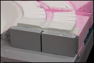
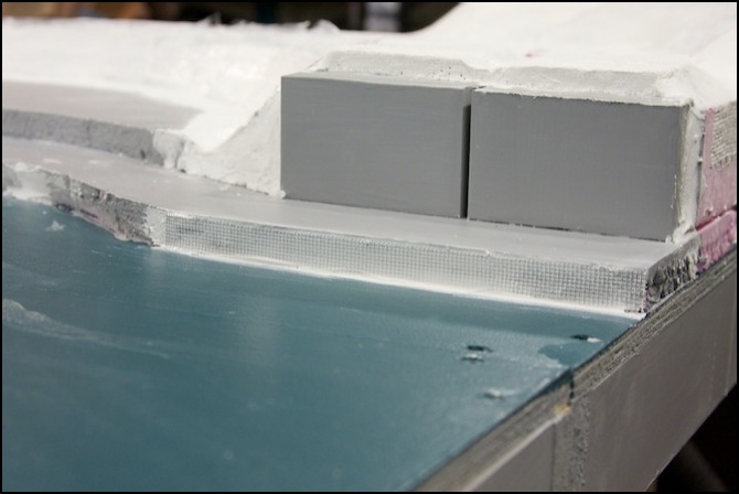
This was getting closer to done, but before I lay down the plaster cloth I wanted to place and glue the bridge abutments, as the ground wraps around them. My solution for bridge abutments is pretty simple: 1x4 pine boards, cut to the appropriate length. I measured them for size assuming a layer of cork roadbed for the track, and cut them to the appropriate length (left photo below), then painted them with two coats of gray latex primer (right photo below), the same stuff I’d used to paint the tables (I still had some left).
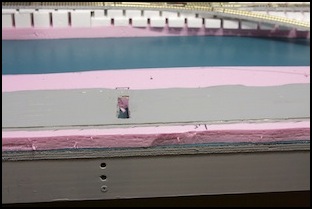
Following this, I painted the flat surface where the village would go as well as the embankment along the river with the same gray latex paint. This won’t be visible in the long run (it will be hidden under buildings or paving), but it gets rid of the pink for now, and provides a neutral color in case any of that foam shows through the eventual scenery. I also painted the foam around the bridge abutments, then glued them in place (more Foam Tack glue).
Foam actually absorbs paint rather well, which is surprising. It took three coats to hide the black pen marks on the pink foam. This is very opaque gray primer, and I only need two coats to hide wood grain, so that was really surprising. I’m beginning to think I may want to paint any foam left exposed with a green or brown latex paint, but maybe I’ll just ensure it’s all covered in plaster.
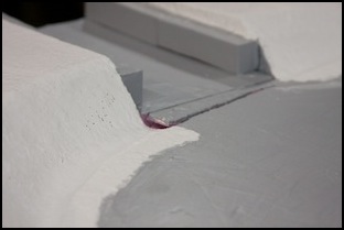
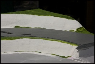
Finally, I put plaster cloth over all of the foam except the flat areas I’d previously painted gray. This provides a base for paint and scenery, and covers up holes and gaps in the foam (e.g., the left photo below where the cloth hides the gap between the gray flat area and the pink hillside). On the bridge abutments, I wrapped the cloth down across the face of the foam above the abutment to prevent a gap being visible between the two tracks. I let it dry overnight.
Note: when using plaster cloth, I put on at least two layers for strength, and rub my gloved fingers across the final layer to ensure plaster fills all the holes in the cloth. This avoids the pink below from showing through.
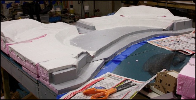
The picture below shows the complete cloth coverage. But there are a few obvious gaps left to fix.
Following this, I filled gaps using Woodland Scenics Foam Putty. This is a very lightweight putty that’s easy to shape with fingers, and can be sanded like foam when it dries. I used it sparingly, mostly to fill a few gaps where I didn’t want to use plaster cloth.
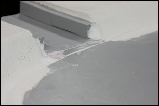
At the road underpass, the small piece of foam I’d put in the gap stuck up a bit too high. I planed it down with a flat Surform, and filled the cracks on either side with the putty (see below). I also put some at the end of the abutment, to smooth off the curve of the landscape there.
Retaining Walls
While the putty set, I started work on the hillsides. These were originally formed of smoothed foam, then coated with plaster cloth. This gave me a fairly flat surface to work with, which was what I’d wanted.
I want these to look like typical concrete retaining walls, which are common in Tōkyō. These have a diamond pattern in most cases, and the color is a reddish-black, likely a combination of soot and dirt over off-white concrete. I’d been inspired by a method I’d learned of from the author of Akhihabara Station, although where he used styrene and paint, I’m using typical landscape materials and ink.
I cut plastic window screen to give me the diamond texture. I test-fit this, and trimmed it to fit without overlapping. The seams aren’t perfect, but will eventually be hidden under a scatter of “grass” since there are often weeds growing between the blocks, or from dirt that’s washed down onto them.
I then applied Woodland Scenics Flex Paste to the hillsides (one at a time) with a putty knife, and smoothed it out with a gloved finger (I discarded the gloves after each of the four hillsides and started over with clean ones, so I could handle the materials with clean hands; I could have cut/fit everything exactly in advance, but I’m not that organized and disposable gloves are cheap in bulk, and I buy them by the carton from the local home supply store). A thick layer isn’t needed, just enough to coat the hillside (much less than 1/8 of an inch).
With the paste in place, I lay each segment of screen down (multiple segments are needed on a curve, to keep the points of the diamond pointing up/down) and pushed it into the paste gently with a side-to-side motion of my fingertip until all of the screen was just flush with the surface of the paste. After all of the sections on one curve were set, I smoothed the paste across them with the side of my finger, to create an even surface. This worked surprisingly well, and any imperfections are small enough that they can later be hidden with scenery material.
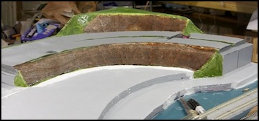
In the first photo below, both curve faces have been coated and had screens applied. In the second paint (an ink wash for the screens) and scenic material has been added.

Plastered Screens
Final Scenery
Another thing I needed to do was put a face on the rough edge of the flat foam along the river and forming the base of the village. I’d thought of a number of ways to do this, but decided to try the paste/screen technique first, this time forming horizontal blocks (like stones). As a test, I did two areas under the bridge abutments on either side. If it didn’t work out, I’d do the rest another way, but it did and I later used this method on all of the exposed edges of the first layer of foam.
I also needed to re-paint part of the river, as flex paste does not come up fully with a damp cloth, so I had some white stains I could not remove. But that was deferred for later, in case I made other mistakes.
Unfortunately, Flex Paste takes a long time to dry (after five hours some areas were still quite wet), so I had to let it sit overnight (there seem to be a lot of “let it sit overnight” steps). However, while it dried I cut out the cork roadbed and glued that down. To do that I re-installed the track briefly to verify it was in the right place, then lifted it carefully off at set it down on a 2’ x 4’ sheet of cork on the workbench, traced its outline, then cut that out with scissors.
I’m using rolled 1/8” (3mm) cork made for bulletin boards, and had unrolled a couple of sheets atop one of the tables built for the storage tracks in December. It sat there with boxes of model supplies on it for two months, which got rid of almost all of the curl, so cutting and setting it in place was quite easy.
So, with the hillsides still drying, and the cork glued down, and a bunch of boards and weights atop it to clamp it in place while it dries, I was through with what I could do that weekend.
Cork Roadbed
After drying, the cork was quite bumpy along the commuter loop where it climbed the incline. Some of this was due to roughness in the plaster cloth where I’d overlapped layers (note to self: keep the roadbed smooth in the future). But part of it was just places that hadn’t glued down properly. I cut those out and re-glued scraps, and it was much smoother. I’m not sure it is smooth enough for real track and ballast, but as long as I’m just using it as a base for Unitrack, it works. And I don’t want to tear it all up, and sand down the plaster at this point, so I’m going to leave it as it is for now.
One of the problems with using cork with Unitrack is that the cork will be visible, unless I want to glue down the Unitrack and ballast it. And that has potential problems with ballast glue getting into the Unijoiners and making the track electrically unreliable. I’m not going to do that. If I want permanent track, I’ll go all the way with flex track, but for now it’s non-attached Unitrack. So, to hide the cork, I painted it gray, to match the Unitrack.
I did this using acrylic artist’s paint. One advantage of this is that it is waterproof when dry (so it won’t be affected by scenery work or eventual ballasting, both of which use water). Another is that it remains somewhat flexible, so hopefully the sound-deadening qualities of the cork won’t be too affected. As a test, I painted the existing cork of the Subway track on the Riverside Station scene using “Neutral Gray #5”. The before and after pictures below tell the tale: the gray is almost exactly the same as that of the Unitrack ballast, and it looks quite good.
After the glue for the cork had dried I cut out openings for the electrical wires to get down into the trenches I’d left in the foam. In the process, I found I’d missed one, and needed to cut a hole on the track furthest from the edge. Since I’m using a two-inch layer of foam, I was able to drill a hole in the middle of it horizontally using a large (3/4”) drill bit, then cut a shaft down to meet that using my steak knife. All told, it worked pretty well, and provided better support for the track than the “trench covered by plaster cloth” method. I’d probably do it this way if I had more track to wire like this.
That done, I painted the exposed plaster with green Woodland Scenics paint (Green Undercoat), let it dry, and then painted the cork gray (see above). I also used the gray to touch up a few embankments that had gotten plaster on them, although this was a darker gray than my latex paint, so I only did that in places where it wouldn’t be obvious. I left the embankments white at this time.
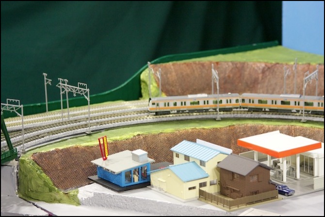
Coloring the Retaining Walls
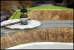
The next part was “painting” the retaining walls. I used a “transparent” acrylic artist’s ink, applied full strength. First I tried a mixture of Burnt Sienna and Burnt Umber on one section, but that came out too orange despite looking good on my test sample of dried flex paste (which lacked the screen). I eventually went with just the Burnt Umber. I applied this with a broad (1/2 inch) artists brush, using vertical strokes from the bottom up. I’d tried dry-brushing first, but quickly realized that the correct technique was to flow the ink on.
The paste had dried with the screen slightly above the surface of the paste (but embedded in it, mostly), and with paste covering the actual screen material, so it was white rather than the black plastic of the screen itself. When the ink was applied, surface tension caused it to pool inside the squares of the screen, turning them a brown/black color, while leaving the screen material a much lighter color. This gave good definition to the texture of the screen, making it more visible from a distance than I’d expected. The first coat (left picture below) came out a bit patchy, and there were some white spots where the ink had totally failed to touch the plaster (some of these were where the screen wasn’t embedded in the plaster, but others were probably air bubbles in the original ink application. I applied a second coat (right picture below) after the first had dried, and this provided a more even color.
Following this, I did touch-up painting of the flat section with gray latex (to cover the white plaster around the edges) and of the green where some of the roadbed gray had accidentally covered the “grass”, and where I had overlooked white plaster previously. This all was left to dry overnight (yet another “overnight”).
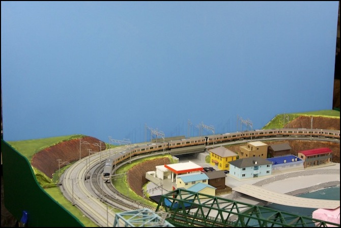
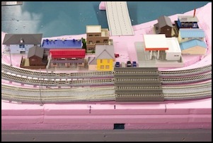
Finished Terrain
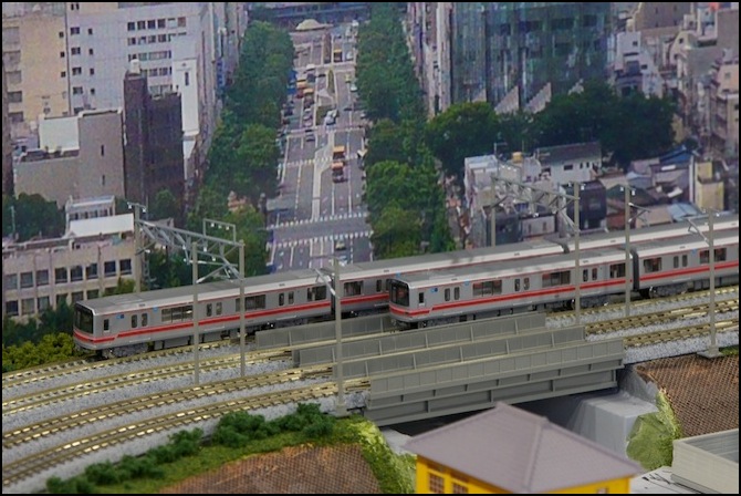
So, having reached a “good enough for now” stopping point, I put the track and the buildings back, and attached the scenic backdrop and fascia boards. And here’s the result, with a train posed above the village: