


DCC Basics: Wiring a Layout for DCC Power
Layout wiring is fairly well documented, and pretty simple when you come right down to it. But I think it’s worth restating some of the basic concepts as part of this section, as this is what I used as the basis of my own layout wiring described in the Electrical Systems subsection of my Model Railroad section. For a discussion of many of the issues in depth, see Allen Gartner’s site on Wiring for DCC.
One word of warning: DCC uses low voltage, so it’s not typically subject to the same regulations as household wiring. But it is high-current AC power, and in a short circuit this will produce a lot of each (enough to melt rails or weld things to them if the circuit breaker doesn’t work!). Working with DCC power systems, particularly the larger ones with 5 Amp supplies, isn’t something to approach carelessly, nor is it something younger children should do unsupervised (a simple plug-and-play all-in-one DCC system isn’t really the same thing, as it uses much lower maximum current).
Additionally, I am not an electrician or an electrical engineer. What I have written here is what I believe, and what has worked for me. But make your own choices and use at your own risk.
Two Essential Tools
There are many important or useful tools when building and wiring a model railroad, and I’ll note a few below, but let me remind you of two I consider essential to anyone building a DCC model railroad of any size or complexity.
A Good Multimeter - In general the digital ones are better, but an analog meter can work. Buy a good one if you can; you’ll only end up replacing a cheap one later. At a minimum for track wiring this needs to measure DC on a 0 - 20 volt scale (having a larger range is better), and resistance on a 0 - 50 Ohm scale (most meters will have a much wider set of resistance ranges). Other ranges aren’t really useful for track wiring, but can be for other things. I have a meter than can measure current in milliamps, and I use that for a lot of things.
A DCC Specialties RRampMeter - This measures both voltage in current in DCC wiring, which a multimeter can’t do very well. You can certainly get by without one of these. You can get by without your left hand too, but would you do so voluntarily? If you want to know what’s really getting to any given spot on the track, or the track bus, this is a very handy tool for understanding that. And it will help a lot in tracking down power problems. The model that comes with an enclosure and test leads (model II) is the one I prefer. The version with battery backup (model III) can be useful if you also work on DC layouts, as the normal kind won’t work if track voltage drops below 7 volts.
Electrical Supply
First off, you need electricity. You can just plug your DCC command station into a wall outlet when in use. That’s all you need for a simple layout. But for something larger you’re going to have a bunch of things to wire up. If you can, connect these all to one wall outlet (unless you hit the limits of that outlet’s circuit breaker) as this avoids any potential issues with ground loops. If you can’t do that, at least make sure all the devices sharing a ground line (DCC command stations, boosters and things like DCC circuit breakers) all connect to a power strip, or strips, connected to one outlet. That’s not critical for things without a grounded plug, but it’s still probably a good idea.
Second, if you don’t unplug things when not in use (and you may not want to, as some devices, like wireless throttles, need continuous power to keep from running batteries down) then split your devices into two groups: those that have to stay on, and those you can turn off, and plug the latter into a power strip with a switch, so you can turn off the whole layout. This avoids running up your electrical bill (those wall-wart transformers use electricity even when the devices connected to them are turned off, and the same can also be true of individual devices with power cords). It may also help protect them against power surges due to lightning, although as long as something’s plugged in, even if it’s turned off, there is often a path for a nearby lightning strike to affect equipment; power switches can’t cut the ground wire, and typically only cut one of the two power wires.
Finally, buy a good surge protector and connect all the power strips to it (or, if you want to spend more money, buy surge-protected power strips instead, but get good ones with a high rating for the number of Joules absorbed and with all three lines (hot, neutral and ground) protected. This way you’ll at least be protected from some power problems. But if you live in an area subject to lots of lightning, don’t count on the surge protector to save you; unplug the things that cost a lot when not in use, and unplug everything if you can (a nearby lightning strike can find its way through any conductor, so if some devices are plugged in, it could get to others through the track).
I’m a particular fan of Tripp-Lite’s premium Isobar line of surge protectors. The IBAR4 isn’t cheap at around US$50, but it handles surges of up to 3330 Joules in its current version, and has a metal case to contain any flames from a really serious surge that melts the protector circuitry, plus a heavy power cord that will be safe up to the full 15 Amp rating. It also has a lighted switch, so you can be sure if it’s on or off in dark under-the-layout installations, and mounting holes on the back so you can attach it to the layout structure with a few screws. I have a couple of these on my layout, but in a hard-to-photograph location. There are other good brands out there, and what really matters is having a good surge protector, not the specific kind.
My layout uses a larger Isobar for the computer and several “always on” things (mainly the supply used by the throttles to keep from running their internal batteries down), into which is also plugged a smaller Isobar with a switch, positioned where I can easily reach it. A long power strip (a four-foot strip with a dozen outlets) is connected to that, and all of the rest of my systems plug into the long strip. Thus, when I throw the switch on the small Isobar, the whole layout other than the computer and the keep-alive power for my throttles shuts down.
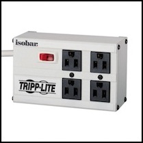
Tripp-Lite Isobar IBAR4 surge protector
Image likely Copyright by Tripp-Lite, but it didn’t say.
Wire and Connectors
Always use stranded wire, it’s more flexible and easier to work with than solid wire, and will last longer in places where it does have to flex. The only exception might be in track feeders, where it can be easier to solder thin solid wire to rail, but even there stranded probably wins. The size of the wire will vary (see below). And since we’re handling low voltages, nearly any kind of insulation will do (house wiring wire for AC power has very heavy and rigid insulation to handle high voltage, and can be problematic to work with; it may still be a good choice for long runs like track power bus wiring if you can get it cheap).
As a general rule for DCC: don’t use wire smaller than 22 gauge unless you know it will be carrying less than the full output of the power supply, and keep in mind that in a short-circuit, like a tool dropped across the rails, any wire without its own circuit breaker could be carrying the full load. If you have a smaller DCC system rated for 3A (like a Zephyr), the magic number is 24 gauge. In both cases, for runs of more than a few feet, using heavier wire is a good idea.
Kinds of Wire
You’d think wire was wire, but it isn’t. I cover this in more detail in my Wire section, but here’s a quick overview.
Wire sold for household wiring comes in solid and stranded forms, and this is also true of some other kinds. Stranded wire is more flexible and will survive more flexing without breaking than solid wire. It’s almost always preferable.
Household wiring also has thick insulation, for handling high-voltage power for decades safely. That makes the wire harder to bend, and physically larger, than some other kinds.
Finally, house wiring is often made from aluminum rather than copper, to save money. Aluminum doesn’t conduct electricity as well, and you can get in big trouble if you connect aluminum wire directly to brass or copper fittings. It can be used, but it needs to be used with care (and how is a more in-depth topic than I’ll cover; consult a home-improvement book that covers electrical wiring, as that’s something they need to describe).
Wire designed for lower voltages comes in several forms, known as primary wire, hookup wire and speaker wire (aka zip cord). Avoid using zip-cord: it’s often cheaply made and hard to work with if you use things like crimp connectors.
Hookup and primary wire both use thinner insulation than house wiring, but still plenty for the voltages used in DCC. This makes it easier to work with and easier to run in cramped locations under a model railroad. Most of this wire will be copper, but some cheaper wire is aluminum. And some high-quality hookup wire is pre-tinned, so it looks like aluminum but isn’t. Primary wire tends to be available in the same large gauges as house wiring, making it a good choice for a power bus or other wire carrying the full output of a command station or booster any distance. You can get it from home supply and marine supply stores. Hookup wire is smaller, and useful for track feeders. You can get a limited selection of it in Radio Shack, although much more (and better prices for bulk) will be had from online specialty dealers.
I use stranded copper primary wire for most of my track power bus now (some parts were done with house wire), and good-quality copper hookup wire for track feeders and wiring from my circuit breakers to the track feeders.
Wire Size, Safety and Voltage Loss
There are two reasons wire size matters. The first is safety: wire has a maximum current it can carry before melting, which is based on its size and composition. In general, wire of 22 ga or larger (smaller gauge numbers) is safe for 5 amp currents between a booster and circuit-breaker, and wire of 24 ga or larger is safe for 3 amp currents, the most you’d normally have in one circuit-breaker section (it’s also the limit for Unitrack). A lot depends on what you consider “normal” room temperature and how well (or how badly) wires can be cooled by air circulation. For this reason, almost every table listing the relevant numbers is different, because a different set of assumptions went into it. I’m using a fairly conservative table (see below) as my source for the above, to provide a safety margin.
The second issue is voltage loss, which is based on Ohm’s law Volts = Current x Resistance. On a DC layout, current is limited to one (or perhaps two) motors, and is well under an Amp. But with DCC, a dozen trains could be pulling power over one pair of wires, and the curent limit of the command station (or booster) is what matters. Here are some typical loss numbers for a typical 5 Amp command station:
12 ga: R = 1.932 Ω / 1000 ft, Loss @ 5 Amp = 0.0097 volts/ft.
14 ga: R = 3.072 Ω / 1000 ft, Loss @ 5 Amp = 0.0154 volts/ft, or 1.5 volts in 100ft
16 ga: R = 4.884 Ω / 1000 ft, Loss @ 5 Amp = 0.0244 volts/ft.
18 ga: R = 7.767 Ω / 1000 ft, Loss @ 5 Amp = 0.0388 volts/ft.
20 ga: R = 12.349 Ω / 1000 ft, Loss @ 5 Amp = 0.0617 volts/ft.
22 ga: R = 19.636 Ω / 1000 ft, Loss @ 5 Amp = 0.0982 volts/ft.
24 ga: R = 31.223 Ω / 1000 ft, Loss @ 5 Amp = 0.1561 volts/ft, or 1.5 volts every 10 feet.
If you only started with 12 volts, and you need 7 to run the train (and you’ll lose some in the track), it doesn’t take many feet of thin wire to cause a problem. This is why it’s a good idea to use wire of heavier gauge for the DCC power bus.
Resistance and other basic figures from a table derated for high-temperatures (i.e., normal loss won’t be as bad, but may approach this due to wire heating from extended use) from this page. Also, resistance is doubled to reflect the “out and back” nature of the wiring, so a “foot” here is a foot of distance from the source, not a foot of copper. I’ve used other ampacity tables at times (like this one).
In general, ampacity tables give two sizes: the size allowed where the wire is in open air (called “chassis” wiring in the linked table) and the size used where it’s in a closed environment like a conduit (called “transmission” wiring in the linked table). So, for open air wiring carrying 5 Amps, 22 gauge is the minimum. Likewise 24 gauge can carry 3 Amps. Unless you bury all your wire inside the layout material, you can use the open air number.
Online tables are really designed for high-voltage power wiring, and DCC is a somewhat different environment. I have been working on my own ampacity table, although at present it’s still based on other tables. Over time I expect to refine it for conditions more specific to model railroading.
Crimp Lugs
Some people like to solder all connectors. That’s a good idea for things that are hard to reach and won’t ever need to be changed, like feeder wires where they connect to the track. I’m less convinced it’s a good idea elsewhere. Two useful ways of connecting wire to other wire are terminal strips with spade lugs, and insulation displacement “suitcase” connectors. You can get both terminal strips and crimp-on lugs at Radio Shack or a home supply store. Use #6 lugs with Radio Shack strips, and typically #8 lugs with the larger home-supply strips. You need to get lugs sized for the size (gauge) of wire used as well. It seems that these are color-coded, with blue being for 14-16 gauge wire and red being for 16-22 gauge, but that may be the particular suppliers I use (two of them have the same convention though).
Spade lugs will work well with wire with a variety of different insulation thicknesses, since they crimp onto the bare copper. Thus these can work with typical house wiring type wire, with “primary wire” and with “hook-up wire”. And I use them will all three kinds. The one thing they aren’t very good with is solid wire; they’re much more reliable when used with stranded wire. When I have to use solid wire, I generally just loop it around a screw on a terminal strip, or solder it to something, and don’t use crimp-on lugs with it at all.
Crimp-on lugs work without soldering to the wire because the pressure of their crimping creates an oxygen-free metal-to-metal bond that can’t corrode (corrosion of the exposed wire can still happen, but it won’t work its way into the bond unless you’re operating in exceptionally corrosion-prone environments, like on a ship. That’s also why lugs on a properly screwed down terminal strip work: a oxygen-free joint between metal created by pressure.
You can put two wires into one lug’s crimp connector if they aren’t the heaviest gauge allowed, and this is handy when you want to connect a bunch of feeders to one distribution wire (you can see a couple of those in the image below).
It’s a really good idea to use spade lugs and terminal strips that are a shiny silver in color, rather than the golden-color of brass. This is because the shiny ones are made with tin or some other material plated with tin, and won’t corrode as easily or as seriously as brass will. In a damp basement, brass gets covered with an insulating layer of corrosion in a couple of years, and that’s not good.
BTW, if you are going to use lugs, you’ll use hundreds of them, so buy bulk packs of 100 to get the lowest cost. Invest in a high-quality crimping tool (for insulated and non-insulated wire) like this one. I have essentially that model bought from a local home-supply store, and it was worth every penny. Your hands will thank you.
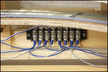
Kato Track Feeders (top) wiring to a terminal strip with bus wire taps using spade lugs.
Terminal Strips
Terminal strips and crimp lugs come in two sizes useful for the size of wire typically used in a model railroad. The #8 connector is larger, and more suitable to the heavy-gauge wire used in a track power bus. The #6 connector is smaller, and preferable for the wire typically used in lighting or track feeders. Radio Shack is a good source for the #6 size, while the #8 is typically found in home supply stores or from specialty electronics suppliers.
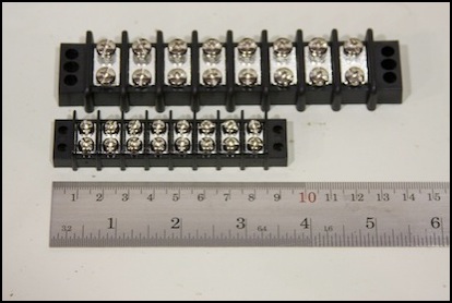
Two sizes of 8-position terminal strip, #8 (top) and #6 (bottom)
Jumper Strips
One thing that’s really useful with the Radio Shack strips (I haven’t found a good equivalent for the larger ones) are something they call Jumper Strips. These are simple strips of metal that slip under the screw on one side, and are connected to bridge several adjacent screws together. This is useful for splitting one output into several. You need a good set of “diagonal cutting pliers” to separate these (and safety glasses; the cut bits are heavy, sharp, and tend to go flying) although flexing them with ordinary pliers may work eventually. You can do the same with loops of wire (with or without spade lugs) or one wire that has several spade lugs on it (actually several short wires crimped into the lugs to act as one longer one). In the diagram further down the page, the “distribution wiring” terminal strip next to the circuit breaker assumes this kind of interconnection.
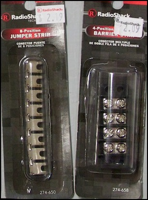
Radio Shack jumper strip and #6 terminal strip
Suitcase Connectors
Suitcase connectors are designed to tap into a wire. They have one slot that slips over the wire, and a second slot with a cap on one end where you feed in a second wire, then you crimp a steel pin down (using a pair of pliers or similar) and snap the connector closed. The 3M company made the originals of these under the brand Scotchlok (although there are now a number of different types of connectors under that brand) and you can find copies by others now. Typically these are color-coded based on the wire gauge, with yellow used for 10 or 12 gauge, brown used for a 18-14 gauge tap off a 12 gauge through wire, blue for a 16-18 gauge tap off a 14 gauge through wire, and red for 16-22 gauge wire (but individual manufacturers or models may vary, be sure before you buy). There are specialty tools for crimping these, but a good pair of pliers will do the job if used with care (I still destroy the occasional connector). Sometimes I regret not buying a better tool, but I use a lot fewer suitcase connectors than lugs, and the tool was expensive.
One important note: suitcase connectors assume the wire is a certain size, and almost all of these are sized for wire with the heavy insulation typical of house wiring or “primary wire”. If you use low-voltage “hook-up wire” this is often much smaller, because which the copper is the same thickness, the insulation is much thinner. This may not work as well (or at all) with suitcase connectors. I only use high-voltage house wire and primary wire with suitcase connectors, and I use terminal strips and spade lugs for all my hook-up wire.
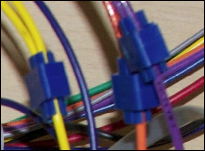
Suitcase connectors tapping the track bus (14 ga wire)
Electronics
In DCC, there are several kinds of electronics. The most important one is the Command Station, also sometimes called the DCC supply. This is the box that either incorporates a throttle or to which throttles are connected (or both). Additionally it usually incorporates a DCC Booster (aka Power Station) to amplify the DCC signal from the minimum 1 Volt (used to communicate with other boosters) to the 7 - 23 Volt signal required on the rails (typically around 12-18V). And it will always incorporate one circuit breaker, to protect trains on the track from a short-circuit.
But in addition to the command station, there can be one or more additional boosters (to provide power for more trains without using very high amperage out of one power supply). Boosters will normally incorporate a circuit breaker as well. Each booster needs to be connected to the command station to receive the DCC signal and to a ground line shared with the command station and any other boosters. Some other devices may connect to this ground as well, as noted below.
Finally, there are related devices that have a role in getting power to the track. These include Circuit Breakers, Automatic Reversers (related to the circuit breaker and sometimes the same device can act as either) and Occupancy Detectors. There are many other DCC devices (e.g. stationary controllers for turnouts) that aren’t part of the power system, but which may connect to it either directly or via the track. I won’t discuss those non-power devices here.
Wiring
Wiring between the Command Station and the track can be as simple as a single pair of wires connected directly to the track, appropriate for a simple layout. In a more complex layout, more complex wiring is often needed or provides an advantage even if not strictly needed.
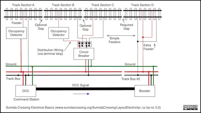
The diagram above shows a command station and booster used to power four sections of track. A section can be any length, although 6’ (2m) is a reasonable upper limit if you divide a layout up like this. That doesn’t mean that you need to do this the minute you have six feet of track. But you’ll see a clear benefit if you have even twenty feet of track or if you want to run multiple trains with shorter amounts of track.
Preferably the command station and any boosters will connect to their own “track bus”: a pair of heavy-gauge wires that follow the tracks, and track feeders will either connect directly to them (via suitcase connectors, soldered joints, or terminal strips) or connect to intermediate devices that connect to the track bus. Note in particular that the bus for each power supply is separate, but that the ground line is continuous, but only needed normally by the Circuit Breaker and Command Station & Booster, although some Occupancy Detectors also need a ground connection. Also, as things like Occupancy Detectors normally only sense one wire, the rail with the other wire doesn’t always require a gap (more on this below). The rail connected to the red wire in this example needs a gap between all four track sections.
Note: the words “section”, “block” and similar may have specific meaning to an individual DCC systems manufacturer (and vary between them), and often have other meanings in model railroading or real railroading (e.g., a track detection block or a signaling block). I’m not going to go into all those here, but be aware of whose document you are reading and what they mean by the term, and don’t confuse it with what someone else may mean. Here I’m going to use “track section” to mean a length of rail with a gap at each end in at least one rail, and “electrical section” to mean a set of devices and associated rails. In the diagram above, B and C form one electrical section because they share a circuit breaker and distribution wiring.
In some cases one section of track may benefit from having more than one feeder to a rail. This can be necessary with switches, for example, where a rail may be isolated by the frog of the switch. In some cases the switch will bridge the gap internally. But in others the rail will need to be fed power separately on both sides. Both feeders could wire together to the bus as shown above for “D”, but they could also both wire to one occupancy detector, if you wanted to treat both sides of the switch as one “occupancy block” for some reason. Or you could wire them to two separate detectors, as shown for A and B (assuming that the gap between them is at the switch).
Track Power Bus
There will be one or more DCC power supplies, usually a command station with an integrated booster, and optionally separate boosters. Each supply will connect to a separate set of track sections. As mentioned previously, a simple approach is fine for smaller layouts, but as things get bigger, a power bus (also called a track bus or track power bus) will make things easier to wire up and to fix. Note that if you have more than one supply, by definition you have more than one power bus and in general it is a good idea to keep them totally separate. The two supplies should be connected via a ground wire as large as the bus wire (that’s called “booster common” wiring, Digitrax uses the name “home ground” to mean the same thing; the alternative is “common rail” wiring, used on some DC layouts, but not recommended between boosters for DCC).
Note that you can use “common rail” wiring between one command station and the feeders, the recommendation above just applies to multiple power supplies. Since you still need the heavy-gauge track bus wire for each rail, and you’ll typically have just the pair of them, unlike a DC layout where each electrical block had a separate wire back to a control panel, there’s less advantage to common-rail wiring for DCC. There may be other reasons to avoid common-rail wiring; see the feeder discussion below for more on this. The main reason to use common rail wiring is when converting a pre-DCC layout, most of which used common-rail wiring, to DCC. Using common-rail wiring for DCC avoids having to add gaps in the common rail and extra wires.
If you have a power bus, the thickness of the wire (wire gauge) depends on several factors. Thicker wires (smaller gauge numbers) are better, up to a point. But you need to take into account how you wire to them. For example, things like “suitcase connectors” can dictate wire gauge: I use a 14-gauge bus tapped with blue suitcase connectors and 16-gauge distribution wiring, in part because that made it easy to find the connectors. The other factor that controls gauge is power loss (and for really small wires, maximum current).
In a power bus, distances are long, so the most important factor is power loss. At the 5 Amp maximum typical of most indoor DCC layouts, 14 gauge is fine, and 16 gauge will work for smaller layouts. If you’re doing very long runs, or using higher-amperage supplies, heavier wiring (like 12 gauge) may be a good idea. The Wiring for DCC site has a discussion of this, as well as more info about power (voltage) loss in wire. I now have some further discussion on this on my Ampacity page.
While two independent wires are easiest to work with, over a long distance they can help distort a DCC signal, due to inductance created by the wire. Some sites recommend twisting the wires together (or using pre-twisted wire, although that’s harder to tap for feeders). The standard doesn’t require this, and rules-of-thumb seem to vary. I’ve seen numbers ranging from two to four twists per foot (meaning six to twelve per meter). When run separately, keeping them well apart (more than 4” or 10cm) can help avoid distortion to some extent. Twisting also helps make the wires less subject to acting as an antenna to pick up other noise. Note that untwisted zip cord (speaker wire) is probably the worst of both worlds; the wires aren’t quite together, but they’re very close, and the wire isn’t twisted.
Note that you don’t need to twist all of it. You really don’t *NEED* to twist any of it. But the issues only affect long runs, so feeders and other short lengths of wire can be left untwisted even if you twist the power bus.
Ground Wire
There are two kinds of ground wires, a “safety ground” is the kind found in typical home wiring, where it is designed to provide electricity a safe path to earth ground in the event of a short circuit, to prevent it from trying to get to ground through you. Electrical systems can also have a “floating ground” that’s really just a way for all components to share the same idea of what “0 volts” means. Depending on the system, it may or may not be a good idea to connect a floating ground to a safety ground.
In DCC systems, a floating ground is used to connect DCC circuit breakers to each other and to the power supply, and to link multiple power supplies. This ground should use wire as heavy as the current-carrying wire (e.g. if wire to a circuit breaker is 16 gauge, use a 16 gauge ground wire there, if wire from a power supply is 14 gauge, use 14 gauge ground wire there). Digitrax says that their ground wire can be connected to your building’s safety ground (and this will actually have some benefit, by allowing static electricity to drain from the system). Other manufacturers are likely similar, but you should consult their manual and reference pages to be sure. If you are connecting a device with an AC input to a safety ground, the wire used should be large enough for the maximum possible current permitted by the wall outlet (typically 15-20 Amps). That means 16 gauge or larger. I used 14 gauge wire for all of my ground wiring, except for short bits of 18-20 gauge used for the inputs to DCC circuit breakers that needed smaller wires.
It’s a common convention to use green insulation (or green with yellow stripes) for ground wires, to make them obvious, and I did this when wiring my layout. But it’s not required by law for layout wiring the way it is for high-power house wiring.
If you do want to connect to the building ground, you need to decide how to do that. Some electronics may have a grounded chassis (e.g., the Digitrax PS2012 does, and provides a screw location you can use to ground the command station; you do need to exercise some caution doing that). Alternatively, if you have copper water pipes, the cold water pipe is usually connected to ground and you can find straps for connecting wire to those in an electrical supply store. On a grounded outlet, the screw holding the faceplate on is typically grounded, so a wire with a lug on the end can be used there.
Note: wiring components to a safety ground isn’t something to take lightly, as you could end up using that path for significant current in the event of a short circuit in the AC power supply. It’s a good idea to use heavy (e.g., 14 ga or similar) wire. Also, there are potential safety issues, so if you aren’t familiar with house wiring, it’s a good idea to have an electrician do the work (if you can find one who will). In any case, that’s something to do at your own risk.
Other Distribution Wiring
If you have devices (like occupancy detectors) between the power supply and the track, you’ll need some wire between them and the power bus, and possibly between them and the feeders. Although you may be able to wire the feeders directly to them, I find it easier to wire the feeders to terminal strips and run wires to those. This wire, which I’ll call distribution wiring, should be kept as short as possible. What I do is tap the 14ga feeder (with a suitcase connector) and wire that to a terminal strip near the electronics, then I run lighter wire (typically 16 gauge) from the strip to the electronics and from the electronics to the terminal strips with the track feeders.
The 16ga wire from the suitcase-connector tap typically ends on a spade lug on a #8 terminal strip. The photo below shows my set of bus wires (I have more than one pair) tapped and connected to one terminal strip (mostly hidden under the wire), and short jumpers from this to a second strip at bottom right, to which the track feeders connect. This is an older photo, and the short distribution wires have been replaced by my circuit breakers and DCC occupancy detector systems on the current layout, which is why I kept these two terminal strips separate.
Note: the reason I have more than one pair is basically due to a misunderstanding as to how much power my trains would use when I designed the layout, coupled with extra pairs used for things like accessory power and my DC test track. You really only need one DCC power bus in any given section of the layout, and I’d do things differently if I were rewiring the layout today.
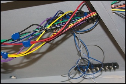
Typical bus taps (colored wires) and on-table distribution (blue/gray wires) to track feeders (bottom right)
Distribution wiring may still need to carry the full 5-Amp supply. This means it needs to be 22 gauge or larger, and I typically use 16 gauge as it minimizes power loss while still being easy to work with. I’ve used 18, 20 or even 22 gauge in some places due to limitations on device connectors. As long as the wire is short, there is only a small amount of extra loss when using the smaller sizes. Just don’t use wires smaller than 22 gauge (24 gauge for smaller 3 Amp DCC systems) unless you’ve got a circuit breaker set to limit current.
Feeders and Rail Gaps
A track feeder is a wire connected directly to the rail, and commonly a pair of these connected to the two rails will be placed together. This needs to be done fairly often, as rail is actually a pretty poor conductor, and long lengths of it will lose a lot of power. Sectional track also loses power at each rail joiner. You’ll see a notable loss of train speed in even 20’ of track without additional feeders. Purists will say that a permanent layout with sectional track needs a feeder on each section, and to an extent that’s good advice, as the connection at each joiner will get worse over time as dirt works its way into any gaps. You could also bridge those points with a short bit of wire soldered to the rail (which still allows the tracks to expand and contract due to temperature changes, unlike soldering the rail joiner itself). In any case, you probably need a new feeder every 3 - 6 feet to minimize voltage loss due to the rail itself.
Note: prototype rail often has wires connecting one length of rail to the next, as electrical continuity is important for signaling (and in electrical railroads for power grounding), so soldering a short length between rails and painting it the same rust color can be thought of as a modeling detail, as well as part of the electrical system.
You can add feeders without adding insulated rail gaps. For example if you want to provide power to multiple lengths of sectional track. You will need to add insulated gaps if you need to keep the two feeders separate. For example, if they have individual occupancy detectors or circuit breakers. You’ll also need to have insulated gaps for things like reverse loops.
Feeders carry less current than most other wiring since they are located fairly often, meaning typically one train can be drawing power through them. They can potentially carry up to whatever your DCC circuit breaker is rated for during a short (the one on the command station could be rated up to 5 Amps or more, but a more likely size is around 2-3 Amps). Kato’s feeders, like their Unitrack itself, are designed for a 3 Amp maximum current, and that’s a reasonable size. If you’re using one big 5 Amp command station, having DCC circuit breakers between it and the feeders set to trip at 3 Amps or less is a good idea. A feeder wire should be as short as possible, to minimize loss, and as small as possible, to make it easier to attach to the track and less obvious. As noted above, for 3 Amps the minimum size is 24 gauge, and that’s usually a good choice.
When it comes to designing feeders, you don’t even need to have insulated gaps in both rails most places you have gaps in one, although it is recommended. You can gap only one rail and have the other continuous (called “common rail” wiring), but this can be problematic for DCC and is mainly a technique for DC wiring (or converting a DC layout to DCC without lots of extra work), to reduce the amount of wire. Even with common rail, some things like reversing sections and separate DCC booster sections need both rails gapped.
When gapping a rail, be sure to plug the gap, otherwise rail may expand in warmer weather until the two bits touch. When I wired up flex track on my old HO layout, I’d superglue a bit of 0.010” strip plastic into a gap (using thick “gap filling” glue), and then cut away excess after the glue fully set using a pair of modeler’s flush-cutting pliers (sprue cutters). I did this before painting the track, so the insulator would be indistinguishable from the rail after painting. You can also use insulating rail joiners between sections of track. With Unitrack, I just use the insulating Unijoiners.
Common Rail
In DC, Common Rail Wiring was a useful technique for blocks. Every power supply had one side connected to the “common” line and one rail was connected to this (and not gapped). The second rail was connected to individual wires back to a control panel, and gapped between feeders. This allowed for independent control of each electrical block, while minimizing wiring. With DCC you don’t need that wire back to a control panel, which eliminates much of the benefit of common rail wiring. You can still do it, and it’s handy when converting a DC layout to DCC not to have to re-do all the track feeders. But it can cause problems with more complex DCC layouts, so it’s something to avoid if you can.
The main issue with common rail wiring to be aware of is that with multiple power supplies (boosters) you need to separate the “common” wiring for the tracks connected to supply #1 from the common wiring for the tracks connected to supply #2, and gap the common rail between rails fed from supply #1 and rails fed from supply #2. That’s a big difference from how supplies shared the common line in DC environments. Trains will still momentarily bridge that gap, but that’s handled by a heavy ground wire between the supplies as described earlier.
A second issue exists if you use circuit breakers. Unless both rails are gapped between a section of rail protected by a circuit breaker and other rail, a short may find a path that doesn’t trip the breaker. In the diagram at the top of the page I showed the gap between track sections A and B as “optional”, and that’s really not true if you have a circuit breaker protecting sections B & C as shown there.
With common rail wiring, you only need to gap one rail (let’s call it the “red” rail) and leave the other continuous (except where you have phase reversals, see below). Occupancy detectors will connect only to the gapped rail. But you still need periodic feeders to the ungapped rail from the black track bus wire due to power loss issues, so all this is really saving you is the effort of making insulated gaps. I just gap both rails everywhere; it’s simpler.
Polarity and Phase
In DC wiring, you have “polarity”, one wire is “+” and one is “-“, and in a model railroad you switch them to control direction, but at any given time, one rail and the wire feeding it will be “+” and one will be “-“. In DCC, the polarity is changing thousands of times a second, but at any instant one will still be “+” and the other “-“, it just happens too quickly to measure with a typical multimeter. Just like in DC, where rails that touch (or that can be momentarily bridged across an insulating gap by the wheel on a train) always need to be the same polarity to avoid a short-circuit, in DCC rails that touch or can be bridged need to both be “+” at the same time. This is called being “in phase”.
If you look at the output of a DCC command station or booster, the two outputs will be labeled “RAIL A” and “RAIL B” or similar. Think of these as the “A” phase and the “B” phase. It’s a good idea to have some conventions for these, like “the Red bus wire always connects to the ‘A’ phase and the Black to the ‘B’ phase” so you can keep other wiring consistent. Also, except where you have to deal with track that forms a loop or curves back on itself, a convention like “the rail to the front of the layout connects to the ‘A’ phase” can be very useful. With a loop, you can do the same thing with “the rail to the outside of the loop connects to the ‘A’ phase”. It doesn’t matter which phases you pick, just pick one and be consistent. With Kato track feeders that have a blue and white wire, I use “Front rail to the Blue feeder wire to the Black bus wire to RAIL B” as my convention (my “three B’s”; I probably should have used “back rail” and had “four B’s”, but I didn’t think of it at the time) . Sometimes this means I need to rearrange my Kato feeder track sections to keep blue to the front.
Reversing and Phase Changes
In DCC, you have what’s called a “Reversing Section” when one length of rail has to meet rails at its two ends that can’t be in the same phase. This means that this bit of rail in the middle needs to have its phase match one end at one time, and the other end at other times. This can happen where track loops back on itself, or where two tracks meet a third in a “wye”, or with turntables, or with some more complex track arrangements. Follow your rails around your track plan, keeping track of “phase”, and if one rail suddenly goes from phase “A” to phase “B” or vice versa, you need a reversing section.
A reversing section needs to be as long as the longest train that can cross it. This is because it’s going to need to swap phases any time a wheel bridges a gap at either end, and if wheels at both ends are crossing the gaps at the same time, problems can result. You don’t need lighted cars or wheels with resistors to cause a problem, all you need are metal wheels. And most newer model trains use metal wheels, at least the good ones.
The device that does this phase swap is called an Automatic Reverser (or Auto Reverse Circuit, or Reverser, or Reversing Circuit Breaker). What happens is that the Reverser is connected in the middle of the feeder, meaning that one side connects to the track power bus (or something connected to that, like an occupancy detector) and the other connects to the two rails of the reversing section of track. The reversing section has to have both rails gapped at both ends no matter how you do other wiring. And you can’t have two reversing sections adjacent to each other (otherwise both reversers will try to reverse their section when a train crosses, which isn’t going to turn out well).
Many diagrams for Reversers show them connected to rails outside the reversing section instead of to the track bus. This works, because those rails are connected to the track bus. However it can cause problems if the rails somehow get reversed or de-powered (due to a turnout switch or other causes) or if you want to use occupancy detectors (a train in the reversing section will be drawing power from the adjacent track, and appear to be in that section). It’s best just to wire them to the track bus (or a device connected directly to it).
Reversers work by detecting short circuits, the same way a DCC circuit breaker does (and some perform both functions). If a Reverser is connected downstream from a circuit breaker (meaning, if there is a DCC circuit breaker between the reverser and the command station) then the reverser needs to be set to detect the short at a lower current than the circuit breaker is set to trip at, otherwise the circuit breaker will just shut off all the track power to the reversing section.
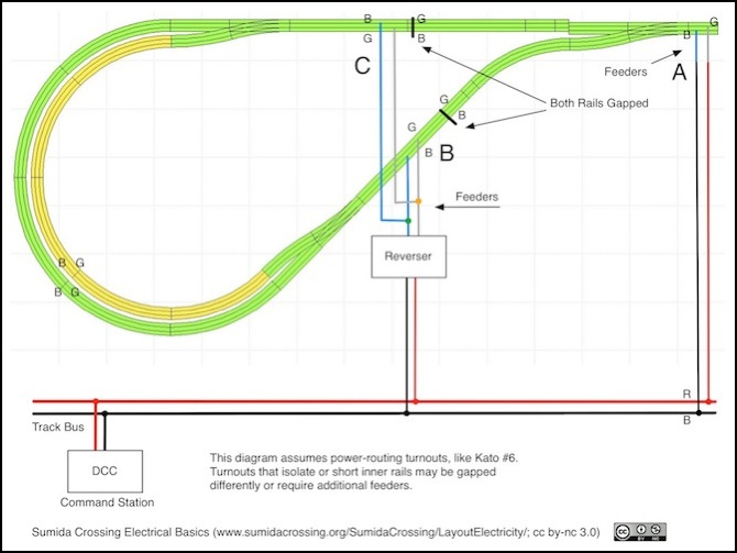
Here is a somewhat complicated reversing section. On the top right, the main track is fed from the track bus. The bus uses Red and Black wires, and at a simple feeder (A) these connect directly to the blue and gray (I’m using gray here, because white doesn’t show up against a white background) feeder wires.
But if you follow the outer rail around it will eventually need to switch from gray to blue, which makes this loop a reversing section (even without the siding in the middle of it). To make this a functional reversing section, a reverser needs to connect to the rails within the loop (at either B or C). If the siding didn’t exist, just one connection (at either B or C or anywhere else) would be needed. With the siding, and assuming power-routing turnouts are used (such as Kato’s #6) and that you want it to work even if only one turnout is switched, both turnouts need a feeder on the point side, and since there are rail gaps at B & C, the mainline feeder isn’t reaching them so this is where the reverser’s output will connect.
There are usually multiple ways to achieve the same goal. In this case, you could gap the two tracks on the left (outer loop and inner loop) where they meet the frog side of the switches, feed both loop tracks from the output of the reverser, and count on the mainline feed to get power all the way to and through the two turnouts. That will work fine if your longest train will always fit in the siding of the loop, but if you want a longer train to pass one in the siding, then the diagram as shown provides a longer reversing section for longer trains. In fact, the B & C rail gaps can be located immediately to the left of the switch at A, which will provide the longest reversing section possible.
The way this works is that when a train crosses a gap between the inside of the loop and the outside (going in either direction), it briefly shorts the track inside the loop to the track outside the loop. If the two are in phase (as shown at B above) then nothing happens and the train moves on. But if the are not in phase (as shown at C), then a short circuit through the train is created. The Reverser detects this, and reacts before enough current can flow to do damage, by switching its output phase. Thus, in the example above while the blue wires at B & C started out connected to the black bus wire, just like the blue wire at A, when a train crosses C the blue wire is switched to connect to the red wire inside the reverser. With the wire switched, the rails on both side of the gap are now in phase, and the train moves on. This all happens so quickly that the train doesn’t slow down.
There are many ways to hook up a reverser, and many instructions will show them connecting the track outside the loop to the track inside the loop. That’s a perfectly fine design in a small layout, but if you have a power bus, they really ought to connect to it.
