


Installing DCC Decoders
Not all trains come with sockets for DCC decoders. Older trains, or those designed recently but without DCC support, require a decoder with wires that can be soldered to the electrical pickups and the motor, and also require some work by the installer to cut or otherwise block the original connection from the pickups to the motor. This page summarizes the issues with this kind of decoder, and briefly discusses the options.
I’ve avoided writing this page for several years, since Don covered the topic very thoroughly on his Akihabara Station pages (links below) and on a pair of threads (Motor Decoders and Cab Decoders) on the JNS Forum. But now that I’m turning my attention to doing some wire-in decoders, I want to have a page to jot down my notes and preferences, as well as a record of what I’ve experimented with. To start, it’s going to sound a lot like a copy of Don’s info, but I did do additional research on manufacturer and reseller websites to compile it (I started with Don’s pages; I’m not an idiot). I’ve also incorporated info from the above-noted forum threads and other sources.
This page is somewhat specific to my modeling, and thus it’s mainly discussing installation in multiple-unit trains where the motor may be separate from the cars with the head and tail lights. It’s also specific to Japanese N-scale models, which tend (except for lightboard issues) to be fairly easy to convert to DCC since the models are plastic and motors are often easy to isolate (Japanese locomotives are a harder problem). There are many other sources on the web for information about converting trains to DCC that go deeper into issues such as bulb replacement or motor isolation. Among these is Allan Gartner’s Wiring for DCC site (the Wiring Locomotives page in particular).
Decoder Types
There are three kinds of decoders in terms of physical installation: decoders designed for a specific model (or set of models) of train, decoders designed for one of the NMRA-standard sockets that can be used in any model with such a socket, and decoders with wires that can be installed in other kind of train models. For my purposes, there are two kinds of model-specific decoders of interest. One type is composed of the Kato-branded decoders (EM13, etc.) that plug into their “DCC Friendly” models. These are covered on my Kato DCC Decoders page. The other are decoders that replace the pre-installed lightboard in models, discussed in my Lightboard-Replacement Decoders page.
Japanese model trains don’t typically use standard sockets, so my only use for these is as wire-in decoders. The remainder of this page will describe installation of both wire-in decoders and sockets, allowing the use of standard socket-ready decoders. Information on the specific decoder models I’d use for this appears on my Wired DCC Decoders page.
Decoder Basics
Wire-in decoders aren’t any different from those that plug into sockets, except for the wires. You could, in fact, use the exact same decoder, and just buy a harness (i.e., a bunch of wires connected to a socket). But for small-space applications, there are some decoders with simple solder pads on them, and wires either pre-soldered or needing to be soldered. In any case, you can’t escape needing to do some soldering on models without a pre-installed socket, as the socket or decoder needs to be connected to the electrical pickups on the model, and the motor. But soldering of this sort isn’t all that hard, just be sure to do your practice on something other than a $300 model; plastic melts very easily at soldering temperatures.
NMRA Recommended Practice RP-9.1.1 documents the standard sockets. The NEM numbers come from European MOROP standards (French page, see the “Norms” links for French and German versions of their standards), but the two describe the same pin arrangements and physical sockets.
Color Codes
The standard color codes for decoder wires are:
- Red = Track, right hand (as viewed by an imaginary engineer in the cab)
- Black = Track, left hand
- Orange = Motor, previously connected to right hand track
- Gray = Motor, previously connected to left hand track
- Blue = function output common (+)
- White = Headlight or function output 1 (F0 normally) output (-)
- Yellow = Taillight or function output 2 (F1 normally) output (-)
- Green = function output 3 (-)
- Violet or Brown = function output 4 (-)
- Black with white stripe = “always on” function output (-)
The red wire can also be connected to third rail or pantograph collectors, although neither of these is typical of Japanese model trains.
The six-pin (NEM651) socket has one issue: it only has pins for track (Red, Black), motor (Gray, Orange), Headlight (White) and Taillight (Yellow); there’s no “common” (Blue). The usual solution is to wire the lights to use one of the rails as the common. It doesn’t matter which, but both lights need to use the same one; the red wire is probably a good choice to ensure consistency and remind you that it’s acting as a + wire (DCC function outputs are negative). You get a bit less light this way, since the track is sometimes at the same polarity as the function output (and hence voltage is zero) due to the AC nature of DCC. That’s an argument against adding a NEM 651 socket in my cab cars.
Note: the pin ordering on the NEM651 is: orange, gray, red, black, white, yellow, with “pin1” being orange (some decoders mark pin 1 with a dot or similar marking).
You could also wire in an 8-pin (NEM 652) decoder socket, which adds a pin for the blue wire, and on some decoders the eighth pin is used to add a third function output. These take up a lot of space in an N-scale model, and I haven’t used them so I don’t have anything further to say about them.
Since function-only decoders are often used in conjunction with basic decoders that support head and tail lights, these will often avoid use of the white (output 1, also known as Function 0 or F0) and yellow (F1) wires, starting with Green (F2 or output 3) wire for their functions, or use other colors altogether.
Most decoders also allow decoder outputs to be remapped to other functions, so even if the default is F2, it may be possible to make it respond to F0. Check the manufacturer’s documentation.
Socket or Wire
A train that lacks a socket does not necessarily require the decoder to be permanently installed. It is possible to wire in either a standard socket or some other unique connector, and use this with either a plug-in decoder or a wired decoder that has had a compatible plug wired to it. For my purposes only four wires are needed. In the cab, these are: right rail, left rail, light function and common. In the motor car these are: right rail, left rail, right motor and left motor. With that, I can use a standard NEM 651 six-pin socket and plug-in decoders (using only three pins and wiring common to one rail contact for the cab decoder, or four pins for the motor decoder). Or I can use a four-position socket and wired decoders connected to a plug.
A NEM 651 socket is a female connector with six positions. Per the standard this has 0.050” (1.27 mm) pitch between pins about 0.017” (0.406 mm) in diameter (and the pins should be circular). ESU sells a socket with 30ga wires pre-attached for US$5 (or less).
Another option (credit to Don of Akihabara Station for the suggestion) is a circuit board header. Digikey S9008E-06-ND or S9010E-06-ND (right angle wires) would appear to work as sockets for NEM 651 decoders, and S9014E-06-ND or S9016E-06-ND (right angle wires) as plugs for a harness to connect a decoder to such a socket. You’d need to solder wires to them, and the holes are square rather than round, but my preliminary testing with a S9008E and a couple of decoders shows that NEM 651 decoders will work with these. This is a very inexpensive solution, as the parts cost around US$1 to $2 each, with discounts if you buy ten or more.
Finally, you could use similar headers in four-pin style, or Miniatronics four-wire connectors (part 50-004-01). The latter are a bit expensive, typically US$13 each, but do work well. The Miniatronics one used heavy-gauge wire suitable for 1 Amp, which is both easy to solder and large enough to be really, really visible. Smaller wires, however, can be incredibly hard to solder onto odd-sized objects like motor tabs or socket pins.
I like the idea of being able to remove the decoder and replace it if necessary, without having to break out the soldering iron. Others might prefer the security of knowing that the decoder isn’t going to have any connectivity issues if it’s soldered in place. And, of course, the extra space required for the connectors and wires leading to them may be an issue. Your milage may vary, but I expect to use connectors, and likely the circuit board headers compatible with the NEM decoders.
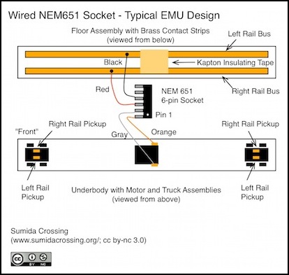
Wiring a NEM 651 Socket into a typical EMU Motor Car (light function pins unused)
Wire Size
The choice of wire size depends on the current it will need to carry. For decoders, voltage loss isn’t a concern (that is a problem with longer wires), and the limiting factor is how much the wire heats up due to its own resistance, and how easily it can discharge that heat to the surrounding environment. Wire in open air dissipates heat more efficiently than wire in a closed space. The type of electrical insulation used also is a significant factor. I’ve made some estimates of how much current wires can carry (their ampacity) based on some online ampacity tables, and quite a bit of reading on the subject. For the details, see my ampacity page.
There are three classes of wire of interest for installation of a DCC decoder: the wire for accessory lights, the wire for the motor, and the wire to the track pickups. Motor current will be equal or less than the stall current, typically much less. But it’s probably safest to consider the worst case, in the event the train gets stuck against an obstacle for an extended period. My typical modern N-scale EMU motors have a stall current around 240 mA.
Lighting (accessory) current will depend on the type of light: LEDs can draw between 5mA and 60mA each (30mA is typical), while bulbs are around 60-75mA. My EMU cabs have up to three LEDs, although these are likely surface-mount elements with fairly low draw, and in many no more than two are lit simultaneously. I’m probably safe in assuming a 100mA current, and it could easily be less than half that. Still, in some cases with multiple bulbs, assuming 200mA may be safer. Also, if more than one accessory output is used, the blue (common) wire needs to be sized for the sum of all of the accessories. That’s true even if the common connects to one of the rails rather than to the decoder (typical of 6-pin socket decoders).
The pickup wire naturally has to carry the sum of these, so with 100mA of lights and 250mA of motor, it could be carrying 350mA of current. Given all the safety margins, I’m probably okay using 250mA or even 200mA as my limit.
Note that if you use a sound decoder, the pickup wires need to carry the power for that, too, which may be substantial.
For my EMU installations, where air circulation may be poor, and power requirements are likely under 200mA, I could use 32ga wire (0.0340 mm2). To be conservative, at least for now I’m going to use 30ga 0.0509 mm2) wire, and that or 28 gauge (0.0810 mm2) is common for decoders. I may use the same for the light function outputs, although I could get away with thinner wire, although I don’t yet have ampacity numbers I believe for smaller than 32ga wire.
Wires within a locomotive body is probably similar. Also note that I’m using a conservative ampacity table, and someone using a less-strict one would come up with different numbers that permit use of smaller wires.
Typical Decoder Wires
Most people working with smaller-scale trains (and even HO) use 30 gauge wire (0.0509 mm2), although some decoders reportedly use 28 gauge (0.0810 mm2) instead.
The ESU NEMA 651 six-pin socket I bought the other day came with 30 gauge copper wire. This is also the gauge Digitrax sells as their decoder hook-up wire, which from my examination appears to be high-quality tinned “hook up wire”. It’s not badly priced either, the list price of US$15 for 90’ is close to the typical price for a 100’ spool, and you get nine colors for color-coding things. Of course, I only need seven colors, and really six would do. I may buy some larger spools from an electronics supply house after I use up my supply of the Digitrax wire.
The Miniatronics connector mentioned above (also available in three-pin and two-pin versions) appears to use heavier-gauge wire (perhaps 26ga, although it’s hard to be certain and it could be 28). The packaging says that it is rated for 1 Amp; this is likely an open-air rating, meaning that it’s 29 gauge or larger.
I picked up some really small-gauge wire made by ESU (part 51940) in a bunch of colors, but this turns out to be too small a gauge (36ga, 0.5mm diameter) for most of my decoder applications. I may use some of it for cab light function outputs however, as it should be okay for the 50-100mA loads there.
Other Factors
Power loss is also an issue with very fine wire. This depends on resistance (you can find calculators for this though google, and I have some tables on my ampacity page). At the currents typical of N-scale locomotives, voltage loss isn’t going to be an issue for the short wires used.
