


Power Pack Design and Testing
I have a number of DC power packs: one really old one from my youth (c. 1970 MRC Throttlepack 501) that has a “Normal/Pulse” switch, one more recent (c. 1990 MRC Control Master II) power pack, and a trio of c. 2009 Kato USA power packs. In addition I have an MRC Tech 4 model 220 (bought 2010) and a pair of Tomix power packs (bought 2011), both purchased after the original testing was done. These cover a span of about 40 years of model railroad power development, from the days when N-scale was a curiosity to the present, where N is the choice of a significant number of modelers (or even a dominant choice, as in Japan). Only the MRC 501 has a “pulse” switch, but it’s not the only one with a non-flat output.
I wanted to see how well these were suited to use with N-scale trains. As part of that, I decided to see what my power packs were really putting out, both in terms of voltage and of what “pulsed” power really meant, and who was doing it. So c. 2010 I hooked several of them up to the track with a test train (an old Atlas B23 I’d picked up some time ago, and use for testing things that might damage the train being used) on it, and my RRampMeter inline to measure voltage and current. Most of the results from that original testing was summarized on the Power Requirements page. In 2013 I bought a new oscilloscope, and discovered that some of the original conclusions I’d drawn based on the original measurements weren’t completely correct, so I’ve re-done some of my power-pack testing.
DC Power Pack Design Issues
The purpose of a DC power pack is to run trains that use DC motors. Such power packs will have a “throttle” control (usually a knob) to adjust output voltage from zero to whatever the maximum is, and a “direction” switch to invert the polarity of that power (since DC motors run backwards when polarity is reversed). How much voltage is needed depends on the type of motor used, and how fast you want the train to run with a given load (and for large trains, how long a train you want to run). Some fancier models will have additional features such as “momentum” controls to limit the rate of increase or decrease of voltage regardless of the speed at which the throttle is turned. DC power packs may also provide “pulsed” power to help with low-speed running. In fact this is so common that some packs that provide it don’t even bother to mention it.
Voltage isn’t normally highlighted in power pack specifications, if it’s even mentioned at all, because they’re all roughly the same and there are standards and conventions for what it should be. And when it is specified, it’s often as an approximate number, since individual units will vary, and output will vary depending on the current local AC voltage (which can change by several percent from one hour to the next). It’s still very important, and I’ll elaborate on that below.
Total power (usually specified in Amps or milliamps, 1,000 mA = 1 A) is also important. A typical modern motor needs very few milliamps to run, and usually a supply of even 500 mA is more than sufficient. But if you want to double-head (run two or more locomotives on one train) or pull very long trains, more power can be useful. Larger-scale motors also typically use more power, so 1 Amp power packs are more typical for HO scale, and large-scale models could benefit from having even more power. Older motors also were less efficiently designed, and need power packs that provide more power. Now that sound systems are more common for trains, power requirements have increased, because a large sound-equipped train can easily use 2 Amps or more of power.
And that’s really all there is to it: correct voltage that can be reversed, two (or more) controls affecting that voltage, and enough power to make the trains move and power onboard accessories like lights and sound. Seems simple enough, doesn’t it? As always, the devil is in the details, and there are a number of things that can make one power pack “better” than another, although any power pack sold for model trains in the last twenty years is likely to be sufficient to run just about any train (ignoring ones with special requirements, such as AC motors).
Voltage Standards and Conventions
There’s no formal standard for model railroad track voltage. That sounds like an odd statement, even a wrong one after years of hearing that HO uses 16V DC and N uses 12V DC. But those are conventions, albeit widespread ones, not a formal standard. The closest I’ve found is NMRA Standard S-9 Electrical, which states that the full-throttle voltage at the rail “shall not be less than 12V” under load. Standard S-9.1 DCC Electrical Standard (PDF) goes on to note that “The RMS value of NMRA digital signal, measured at the track, shall not exceed by more than 2 volts the voltage specified in standard S9 for the applicable scale” (but there isn’t one defined in S9!). S-9.1 also states that command stations should not output less than 7 volts nor more than 22, which seems to redefine the minimum in DCC environments. And it states that N-scale decoders should survive track voltages as high as 24 volts, which implies that there are or could be some DCC command stations (or perhaps DC power packs since many DCC decoders can operate on DC) with track voltages that high.
S-9.1 also includes several charts showing minimum and maximum voltages for power stations and decoders along with “typical” voltages per scale, and that’s the best guidance we appear to have. This shows N scale as having a “typical” voltage of 12 Volts DC, and HO and O of 14.5V DC.
For European modelers, things are a bit more clear, maybe. NEM 630 (French PDF) states that “nominal voltage” for gauges larger than 6.5mm and smaller than 32mm (which encompasses N and HO, but not O) must be 12V. I’m not sure if that’s really a “must”; it sounds more like the NMRA’s “typical” voltage except that’s it’s formally specified in the NEM standard. It also provides correction factors for converting to an effective DC voltage from a voltage (I believe the voltage meant would be that read on a DC meter showing the peak voltage) for half-wave (0.64) and full-wave (0.90) pulsed power. I’m not sure where those factors come from, because usually pulsed power is based on a sine wave, and RMS voltage of a sine wave is 71% of peak. Torque is linear with current, and current with voltage, so the ratio for effective force produced by a motor should also be based on 71% of that produced if the peak were constant.
Note: the NEM correction factors also appear to assume a simple (unfiltered) waveform. That’s not what you’re getting with more modern power packs when pulsed power is provided, and an “RMS” meter isn’t going to provide meaningful numbers if you don’t have a clean sine wave waveform. However as noted above neither is the right number for an RMS conversion (which would be 0.707, or 71%, for a clean AC sine wave). In any case, there’s no quick and accurate method to convert some of these waves to “effective voltage”.
So, there’s no worldwide common standard, and anecdotal evidence suggests 12V is used for N, with HO having a nominal voltage of 16V, not 14.5V (except perhaps in Europe). Note, however, that a full-wave 16V peak has a corrected voltage (per the NEM 630 formula) of 14.5V, which could be the origin of that number (but RMS voltage would be 11 V). In a similar manner, a full-wave equivalent of 12V would be 13.3V, and if 12V is the full wave, then its “effective” voltage would be 10.8V. So it’s unclear why they didn’t put 10.8V in the table. It’s all rather confusing.
The bottom line is that DC voltage should exceed 12 volts at the output of the power pack at maximum throttle, assuming a constant voltage. Maximum voltage isn’t defined, but for HO it’s conventionally somewhere around 16 to 18 Volts, and could be larger in either case. There is no minimum voltage. At some level, the train stops moving, but that level will vary from one model of locomotive to another.
Of course, most power packs (in the U.S. anyway) are built for use with HO-scale trains, and thus U.S. N-scale motors ought to be able to tolerate those higher voltages. Things in Japan are a bit different, and track voltage is nominally 12V on both Kato and Tomix power packs (some Tomix packs designed for trams are an exception). In fact, measurements on a pair of Tomix packs showed that despite having a nominal output of 12V, their actual maximum voltage was somewhat less. So trains built for domestic Japanese use may have lesser tolerances and could potentially be damaged by higher voltages. I’ve heard that that’s the case with some smaller tram (light rail) models, but don’t have personal experience of them.
However, while it’s important to be aware that trams may be more sensitive to higher voltage, for the most part it’s likely safe to assume that any modern train is going to be fine on typical HO power pack voltages of around 16 volts. There’s no guarantee of this, particularly for Japanese N-scale models, and some nominally “HO” power packs have voltages much higher than 16 volts, so it is an area worth paying some attention to.
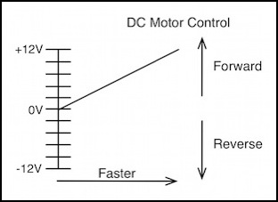
DC Voltage for Motor Control
DC power is normally of a constant voltage, and that’s usually increased directly in proportion to the throttle setting. I.e., a 16 volt power pack set to 50% power is likely going to output 8 volts. DC motors have linear speed changes (without load) based on voltage, so a 12,000 RPM 16-Volt motor receiving 8 volts will turn at about 6,000 RPM (all somewhat approximate). But under load, motors don’t quite work like that, because some of the power goes to dealing with the load, rather than simply spinning the motor. So that same motor at 50% power pulling a light train will be turning a bit less than 6,000 RPM since some of the power is being dissipated to overcome the “drag” (friction in all of the axles, plus any friction in the geartrain of the loco itself). And if you make the train heavier (more or heavier cars) the friction increases, the “drag” increases, and the motor speed drops.
Variable-Voltage Control of DC Motors
If you remember high school physics there are two kinds of friction: “static” friction occurs when trying to start something moving, and “dynamic” (or sometimes “kinetic”) friction when trying to keep something moving. In almost all cases the static value is higher than the dynamic one, which means that it takes more power to start a train moving than to keep it in motion. For a train made with modern materials (steel wheels in low-friction plastic bearings) the difference is likely to be around 12% (approximate, since it depends on the specific materials). For older trains with steel wheels on non-lubricated brass frames it could be much higher, closer to 50%.
Note: static or “starting” friction is sometimes referred to as “stiction” (a contraction of “starting friction” or perhaps “sticking friction”) when talking about motor design.
With fixed voltage, both the average and peak power in the motor are the same (if you want to get into the physics, we’re really talking about force, meaning torque in the armature). Low frequency pulsing of the power creates a high peak voltage, and a lower average one, and thus a higher power (torque) working to overcome static friction. Once the motor starts moving, the lower average power (torque again) comes into play, and it’s this that works against the drag of the train (dynamic friction) to determine the speed. Thus pulsed power will let a train start moving at a lower speed (average voltage) than non-pulsed power.
Pulsed or Rippled Voltage
One of the features claimed by a number of packs (and provided by some that don’t claim it) is “pulsed” power, but what does that mean and why is it desirable? Is it even desirable?
Pulsed power can come in several forms, and this can include a constant voltage to which the pulses are added, or the pulses may be the only voltage. The frequency (how often the pulses repeat) can differ, as can the width of the pulses relative to the gaps between them. And while the graphic below shows pulses that go immediately from zero to the same maximum, the maximum can be varied to control speed or (in the case of pulse-width modulation) the width of the pulses can be varied to control speed. Also, pulses need not go abruptly to the maximum, then may rise and fall gradually, with either a straight slope or a curved one. The latter is typical of pulses derived from AC power in analog systems, which square-edged pulses are more typical of digital control systems.
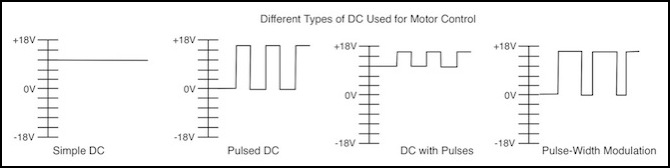
Different ways to use DC voltage to produce a constant speed
Pulsing is advantageous because it tends to provide better low-speed operation, due to the way DC motors work, as described in the previous section. The downside is that pulsing the driving voltage puts more stress on the motor. There are two aspects to this. First, higher current at the peak of the pulse creates more heat in the motor’s armature windings (typically just referred to as “heating” of the motor), and a slow-turning motor doesn’t cool itself very well. This could lead to motor damage from overheating, particularly at low speeds. Second, as the voltage goes from a low level to a high level there is increased magnetic-field strength, causing increased force between the armature windings and the permanent magnets on the frame. With a sine wave, this is spread out slightly, while with more synthetic “square” waves this can be very abrupt. Some concern has been raised that the repeated shocks from pulse-based changes could lead to motor damage, although this is not generally considered to be an issue with modern DC motors.
While this is a somewhat contentious topic among modelers, the current thought is that modern motors are well-suited to this kind of control, which is used in all DCC decoders (and many other modern motor-control systems). Still, in the early days of throttle design, pulse-based throttles were reported to have damaged some motors. Since pulsing is most important at low speed, in the ideal case these pulses would be reduced as the throttle setting is advanced towards the maximum, so that only trains running at low speed for an extended period would be exposed to any potential risk.
One possible exception is coreless motors. These have less mass to dissipate heat, and are thus more sensitive to pulse-induced heating at low speeds, when they’re unable to cool themselves from air circulation caused by the spinning armature. Coreless designs are more common in European models than U.S. or Japanese ones, although Kato’s Unitrams are reputed to use coreless motors (and Kato’s DC packs use a form of pulsed power, although it is one of the milder approaches).
A DC power pack needs to convert wall power, which is Alternating Current (AC) at a relatively high voltage, to low-voltage Direct Current (DC). This is a two-stage process. First a transformer alters the voltage from the high level to some useful level. For a power supply that will ultimately provide 12 volts to the track, this is likely to have a peak voltage of about 18 volts, which most meters will report as 13 Volts AC RMS (RMS voltage is a measure of the actual power provided, and is 71% of peak for a sine-wave). The second step is to “rectify” the AC voltage, which changes direction (i.e., reverses polarity) 120 times a second (roughly every 8 milliseconds) into a voltage that varies from zero to the maximum. The usual method to do this uses the whole wave, and is called “full wave” rectification, but using only half of the wave (“half wave rectification” as if you couldn’t guess) can also be useful. Both full and half-wave rectified current are considered “DC” since they don’t change direction (polarity). However, unless filtering is also applied this does not produce a constant voltage, but rather one that varies from zero to the maximum of one of the input peaks (actually slightly less than the maximum, as the “rectifier” circuit usually consumes about one volt).
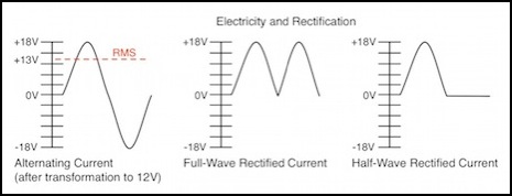
If the voltage is then filtered, the result would be a constant voltage at the “Root Mean Square” (RMS) voltage. For a typical AC sine wave, RMS voltage is 71% of peak voltage. So if you started with 18 Volts AC (which has an RMS voltage of 12.8 volts) and ran it through a rectifier, then filtered it, you’d end up with a constant DC voltage of about 12 volts ((18*0.71)-1 = 11.8). But if you don’t filter it, you still have the same amount of power as the filtered form, but it now has a higher peak voltage (closer to 17 volts).
Rectifiers also lose some voltage. This can vary from about 1.0 volts up to 1.6 volts depending on the exact components used. So power supply maximum DC will be a bit less than the calculation above shows.
A pulsed system based on AC waves will have pulses 41% higher than the average. That might not be enough to kick loose a really old train model at low throttle, but it’s more than sufficient for any modern design. Thus most DC power packs simply create pulses derived from the 60 Hz AC power sine wave, or some variation on it (i.e., they’re using the full or half-wave rectified voltage, perhaps with some modifications). The technical term for this full-wave rectified DC output is “rippled” (or more correctly “unfiltered rippled”), but it’s often simply called “pulsed”. For some additional background, and a bit of history on use of this kind of power, see this article.
Technically any short-lived change of voltage (up or down) that returns to its original state is “pulsed”. In DC motor design, “pulsed” is usually used in the context of a repeating sequence of variable-width pulses used to drive a motor when voltage can’t easily be varied. This is called Pulse-Width Modulation (PWM), and it is typical of many digital small-motor controllers, including DCC decoders. But PWM is not normally used in DC power packs. Power pack designers aren’t wrong to call “rippled” power “pulsed”, but it may be misleading for people who assume it refers to digitally synthesized output pulses.
Linn Westcott did the pioneering work on this kind of pulsed power in his “True Action Throttle” (TAT) series of circuit designs, published in Model Railroader magazine in the late 1960’s and 1970’s. Some of the reports of damage from early throttles many have derived from the type of pulsed power used in his early designs. Today’s DCC decoders use PWM control that builds on his early work, but with a lot more knowledge of the kinds of problems that could be caused. Additionally, motors designed in the last twenty years are more suited to being driven by artificial waveforms, as such controllers have become much more common in all kinds of applications, not just in model railroading, as high-power transistors became more affordable.
Frequency of Pulsed Power
As noted above, the frequency of analog-derived pulsed power is based on the frequency of the original AC power, meaning either 60 Hz (one pulse per cycle for half-wave rectification) or 120 Hz (two pulses per cycle for full-wave rectification). This is fine for pulses that are close to the same width as the gaps between them.
With PWM a synthetic pulse that switches between zero volts and full voltage is used, and the width of the pulse can be varied to control average voltage (power, torque). At low throttle settings the width of the pulse will be quite short, and the gap between them relatively long. With these kinds of pulses, higher frequencies are more important, as these are necessary to ensure that the magnetic field in the motor is maintained over a long gap. Higher frequencies also help to shift the noise created by vibrations in the motor from those abrupt pulses out of the range of normal adult hearing (so-called “supersonic” decoders typically act at about 15 kHz, which younger modelers can still hear). Noise is less of an issue with gradually-changing voltage (the sine waves and modified sine waves of DC power packs), so DC packs can get away with using lower frequency without adding unreasonable noise.
And, as a result, DC power packs rarely (if ever; I don’t know of any examples) use PWM. That’s not to say they couldn’t. Plenty of people have hooked up DCC decoders to a length of track to run a DC train, which is doing exactly the same thing as a DC PWM power pack would do. And Arduino motor controllers use PWM in this manner, and some people (including me) have run trains with those.
The bottom line is that in DC power pack design, “pulsed” does not mean “PWM” or high frequency. At least not most of the time. I’m going to use “ripple” or “rippled” in the discussions below where I’m referring to apparent use of unfiltered or partially filtered AC, and “pulsed” for artificial waveforms, even if they appear to be triggered by AC behavior (i.e., occur on 8 or 16 msec cycles).
Polarity
A properly-made model train will run “forwards” when the right-hand rail (as viewed from the perspective of an engineer aboard the train) is at a higher voltage than the left-hand rail. This condition is described as the right-hand rail being “positive” relative to the left-hand rail (which is negative). It’s only relative voltage that matters; neither of these needs to be at or below some “ground” level.
DC power packs, however, typically don’t label their track outputs in any way, nor do they label the direction switch, so for most purposes this is rather arbitrary. It does mean that if the direction switch thrown “left” causes one loco to run forwards, it should cause any other to do so as well.
Kato is an exception in that their direction switch is clearly marked with “forward” and “reverse” positions. And their output plug is polarized so that “forward” always makes the white wire on their track feeders positive relative to the blue one. Which rail this connects to depends on how the feeder track is connected, but if you put white on the right from the train’s perspective, the train will move forward when the direction switch is set to “forward”. Of course if you have the locomotive facing the other direction, it will run backwards when the control is set to “forward”.
If you use a Kato pack and want to replicate Japanese left-side directional running, the white wire should always connect to the inside rail on double track. Aside from that one case, it really isn’t going to matter.
In short, the function of the direction switch is to provide two different polarities, but which is which doesn’t matter.
Surge Protection and Circuit Breakers
All DC power packs have circuit breakers protecting their outputs from a short-circuit. Sometimes these are self-resetting (they turn the power back on after a few seconds), others pop out a button that needs to be pushed back in once the cause of the problem is fixed. This protects the power pack if someone manages to put something conductive, like a derailed train, between the two rails, or makes a wiring or track mistake that connects the left rail to the right rail somehow. That’s something I still manage to do routinely after decades of experience, so it’s a good thing they include these.
None of these protect the power pack from the outside power supply. Modern power packs contain fairly complex digital circuitry, and need the same kind of protection against surges and spikes that any such electronics need. In short, it’s a good idea to plug a DC power pack into a surge protector, rather than directly into the wall.
There’s another benefit to that: what comes out as a DC voltage is typically directly derived from the AC supply. Some “regulation” may be applied to limit this, but you can’t count on that. If a voltage surge comes through and you haven’t protected the pack, then a reduced version of it will go into the track if the throttle is on. This isn’t likely to be enough to cause a problem unless you’ve had something serious like a lightning strike (and even a surge protector may not help with those; unplug the pack when not in use if lightning is expected). But it’s still a good idea to have that extra layer of protection between the expensive trains and the outside world.
Testing The Power Packs
Just to be clear: this isn’t a formal comparison between competing manufacturers. This is an analysis of the DC power packs I own, to understand their behavior and satisfy my curiosity. I have a fairly interesting (I think) cross-section of packs, so it’s probably of interest to others. But I’m not in the business of doing reviews. As always, the information presented here is true to the best of my knowledge and reflects my own observations unless noted otherwise. I don’t accept recompense from manufacturers (or anyone else) for what I say on this site. If anyone does feel the information presented here is incorrect, feel free to drop me a note at the address on the About the Site page.
Testing the power packs consisted of running an N-scale locomotive (an Atlas B23) around a loop of Unitrack, and measuring the output of the pack with a multimeter and oscilloscope. All tests had the locomotive proceeding in a “forward” direction, with the meters set up to read the white wire (right rail) as the positive one. Readings below are “eyeballed” from the screen markings.
Heating Test
One thing I’d been concerned about was whether modern pulsed power would cause the locomotive motor to heat at low speeds, when it was getting the maximum effect of pulsed power, and the minimum motion to help cool it. Thankfully those fears appear unfounded. I did not, however, test the older packs for heating effects, as I’m not using those with my N-scale trains.
On the MRC 220, the maximum amplitude of the pulses appeared to be about 8V, and by the time the voltage had risen to 10V the output was perfectly flat DC, with no AC component. On the Kato, 5V was the minimum that would keep the motor turning reliably. The MRC appeared to work at lower voltages, but this may have been just the meter reading wrong due to the pulsed power, as rotational speed seemed similar to the Kato 5V test.
I tested with both the standard Kato Power Pack and the MRC 220, at 5V and 10V, letting it run for 30 minutes each time to stabilize, and sit idle between tests until the motor cooled to about 70°F or 21°C (room temperature was in the low sixties). The maximum temperature reached by the motor was 89.8°F (32.1°C) during the Kato 10V test. The MRC 10V test reached 86.8°F (30.4°C) at one point, but dropped slightly by the end of the test. All lower-voltage tests ran cooler, indicating that there was no negative effect from the pulsed power.
Output Waveforms
A simple DC output graphed on an oscilloscope would be a rather boring straight horizontal line (and it is for the two Tomix packs so I didn’t include them here). Any deviation from this shows an AC component has been superimposed on the DC, either left over from the original wall outlet waveform or a deliberate imposition of AC pulses.
The new scope traces (blue border around a black center) are date stamped and show when they were made. These were all done with the horizontal center line representing the reference “zero” (the left rail for track measurements) and the graphed line representing the measured voltage (the right rail for track measurements) relative to that. I also made measurements using a “true RMS” multimeter of AC and DC voltages. The scope was bought in early 2013 and was calibrated when purchased. The multimeter was not calibrated within the last year, but was at one time calibrated and I have no reason to believe it is significantly wrong (and they agree with each other, to within a tenth of a volt or so, when I compare them).
Older oscilloscope traces (purple screen) are from my old handheld scope, and were taken c. 2010. It wasn’t very reliable, but the general shape of the waveforms should be correct, and the measured numbers where usually correct unless something confused it.
The photos below (larger versions in the DC Testing photo album) show oscilloscope traces of my power packs in action, with a small locomotive on the track. Voltages are reported as peak-to-peak (PtP) based on the oscilloscope screen markings. I also took current measurements, but the erratic voltage made my meter readings unreliable.
Accessory Outputs
DC power packs have historically had a fixed voltage output for “accessory” use, used for things such as electromagnetic turnout switches and bulb-based scenic lighting. These were typically AC power tapped off the power pack’s transformer output before it was rectified to DC, thus it would normally be 60 Hz AC at some unregulated but safely low voltage. But “safely low” for humans does not necessarily make it safe for modern electronics. And there’s no standard for what this accessory voltage should be, or how much current can or should be provided. As you can see below, there’s a lot of variation in accessory output voltage levels, and often what comes out has nothing to do with what the label on the power pack actually says.
Because this is an unregulated output from the transformer, this is also going to suffer from the problem that small transformers sag under load, so unloaded voltage is higher than the rated voltage. For this reason the accessory voltage when you aren’t running a train will be several volts higher than it is when you are running a train that’s a significant percentage of the power pack capacity.
You really shouldn’t use DC power pack accessory power for modern electronics, and if you do, you really ought to check it with a meter to see if what you get is what you expected, and even then the electronics have to be able to tolerate a lot of variation. Variation in the supply power can cause microprocessor-based accessories to misbehave, another reason for not using this with modern electronics.
Testing for the accessory outputs mostly consisted of checking with my multimeter set to the AC RMS scale. If DC output was claimed, I measured with the DC setting unless noted otherwise. However, be aware that this measures peak voltage DC. DC produced from rectified AC has high peak voltages that are normally “smoothed” with a capacitor to an average voltage, but unloaded this won’t produce “average” voltage as nothing drains charge from the capacitor between cycles. However, modern accessories don’t draw a lot of current to begin with, so this peak voltage may be a more accurate measure for typical use anyway.
If you get the impression that accessory outputs aren’t a reliable power source, good. They aren’t.
The Power Packs
The older packs described below are the ones I used in the past, and were “good” power packs for their day. Not the best by any means, but above average. And the fact that the old MRC 501 is still working after decades spent in damp basements with occasional use is a tribute to its rugged design; it served on three different layouts over more than thirty years of use before I retired it. And I still use it from time to time when I need to test something, although the direction switch has recently started having problems, and it is probably time to retire it for good.
Tyco
Peak Voltage: TBD (label says 18V DC max)
Amperage: 333 mA (claimed)
Accessory Output: TBD (label says 20V AC)
I haven’t formally tested this yet, aside from a couple of simple measurements. This is a basic “trainset” power pack. I had one almost exactly the same on my first-ever model train set, back around 1970. I picked this one up for US$5 on a clearance table at a local hobby store in 2016. God only knows how long they’d had it. I’m not sure it works, as the voltages were way too high to be reasonable, although that might change under load. However I’m not going to risk any of my locos to this thing; the numbers were that bad. The case is riveted shut, but I’m going to drill those out so I can see what kind of circuit it uses.
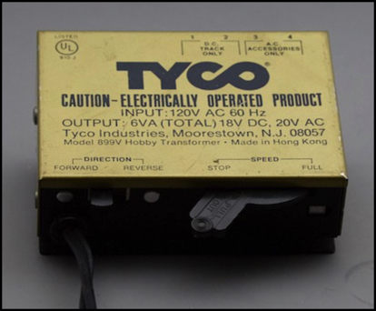
Tyco Hobby Transformer
All the basics are here: a direction switch and a throttle lever, two screws for track power and two screws for AC accessories, and a power cord. It claims a 6VA output at 18V, which seems a bit light (that’s 333 mA), but probably enough to run one locomotive even in HO scale, but perhaps not as fast as you might like if you were 12. I don’t recall any problems with mine being able to run the several locos I had back then, but even at 12 I was more interested in “realistic” operation than speed. Note that the accessory output is rated for 20 volts; rather high, but back when this was designed, the only thing you’d connect to it would have been lightbulbs and solenoids.
MRC 501
Peak Voltage: ~25V (approximate)
Amperage: 1,600 mA (maximum)
Accessory output, AC: 18.6 V (label says 16V AC)
Accessory output, DC: 17.0 V (label says 12V DC), only in “Full” mode, 0V in “Pulsed”
Pulse Type: Ripple, 120 Hz full-wave/ 60 Hz half-wave, switchable, with a DC component
The 501 is an example of pre-solid state design; there are no chips here, just a basic transformer/diode/rheostat design with some added bits, putting out up to 1.6 amps. The Pulse switch just turns off one of the two rectifier diodes. This design was in production through at least the 1980’s, although mine dates from the early 1970s (maybe c. 1973 or 1975). You can still find these things for sale on E-bay and other places, and if you can pick up a working one for under $20, it might be okay for HO use. The voltage is a bit high for N-scale use and it doesn’t work very well with modern low-current train motors though.
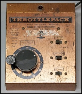
MRC 501 and Interior
As designs go, this is pretty crude. They knew how to make better throttles in 1970, but this was cheap to build and it probably worked quite well with locomotives of the day. I received it as a Christmas present (I still remember unwrapping it!), and I recall being quite pleased with it for my HO trains, compared to the really cheap Tyco transformer that came with my original set, which I’d been using for a number of years. The large knob, smooth feel, and fine degree of control (relative to the Tyco anyway) were just wonderful. The intervening 40 years have seen a lot of development though, and you can do a lot better today.
In particular, speed control with a resistor-based throttle does not work well with modern low-current motors. Low-speed with my test locomotive was quite fast on either setting, although with the switch set to “pulsed” power it was slower, and the throttle worked down to about 8% (versus 10% and significantly faster speed on the “full” setting). The speed did increase as the throttle was advanced, but most of the change happened before the throttle reached the 30% setting.
MRC 501, Slowest possible speed (still fast), on “Pulse” setting, 8% throttle
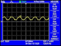
MRC 501, “Full” setting, at 30%, 50% and 100% throttle (with loco)
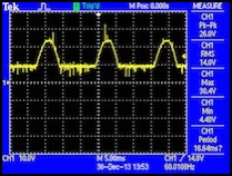
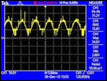
MRC 501, “Pulse” setting, at 30%, 50% and 100% throttle (with loco)
Measuring this power pack has proved problematic. My RRampMeter couldn’t get a reliable lock on it due to the AC (a problem it didn’t have with other power packs with a ripple component, so I suspect the amount of noise in the signal was part of the problem). The new scope did a decent job, although I don’t trust the numbers reported in the right column very much (see the photo album copies if you want to read those). As can be seen from the scope traces, this is using the unfiltered AC ripple to provide pulses above a base level of DC (I’m not sure where the level DC component is coming from; perhaps one of those disks is actually a filter capacitor).
By eyeball, I can tell from the screen of my oscilloscope that peak voltage (ignoring noise spikes) is around 20 volts at 50% on “pulse” and slightly higher on “Full”. This rises to 24 and 25 volts at 100% throttle. There’s a DC component that rises quickly between zero and 30% throttle (it’s at about 3 V when the loco starts to move), and is around 10 - 12 V at 100% throttle (and not much less at 50%). If the RMS reading is to be believed, and I’m not sure how accurate it is with this kind of waveform, that voltage rises to 18.7 V at 100% throttle in “Full”, and 14.0 in “Pulsed”.
The half-wave ripple power provided on “Pulsed” has a slightly higher ratio of peak to average power than the “normal” full-wave form, which could be helpful when dealing with older models that have very high levels of friction in the motor drivetrain or in older wheel bearings of the cars being pulled. Even the normal full-wave ripple is still a form of pulsed power through, and the differences don’t appear all that significant: at the lowest speed, the ratios are 1.8:1 vs 1.4:1.
I ran across a comment online that noted second-hand that some trains had been damaged through the use of half-wave pulsed power on “some controllers in the 1970’s”. It was very anecdotal (nothing specific about throttle or train, and it was an “a friend of mine told me” comment), and probably depended on the motor design (coreless motor designs are more vulnerable to heating, for example). Still, if you have one of these, avoiding use of the “pulse” switch with trains made in the last forty years might be a good idea.
I also measured the two accessory outputs. The “16V AC” output provided 18.6 V AC RMS, while the “12 V DC” output provided 17.0 V DC in “full” mode and was off in “pulse” mode. The DC is probably an odd voltage due to the half-wave rectification used here (the average voltage will be lower than if full-wave was used).
MRC Control Master II
Peak Voltage: ~19.3 V (unloaded, may be RMS)
Amperage: 750 mA
Accessory, AC: 17.9 V AC RMS
Accessory, DC: 22 V DC (flat DC, but the label says “12V”, not 22)
Pulse Type: 60 Hz half-wave ripple superimposed on rising DC
The second MRC is a Control Master II I bought around 1990 when I was getting back into trains and needed a second power pack for my HO layout. This is an early example of a “solid state” power pack, meaning that more was done to manipulate the output. Mainly this shows up as “momentum” and “brake” switches that caused the output voltage to ramp up and down more slowly than the knob was turned, or to ramp it down even if the throttle is set, to make acceleration and braking more “realistic”. I also found it to work better with a modern N-scale locomotive, although the relatively high voltage makes me shy away from using it for N-scale trains.
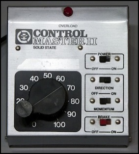
This model wasn’t as popular as the old 501, but some are still in use. I haven’t managed to get the case open on this one. It uses some kind of oddball security screw, as does the later MRC 220; apparently they don’t want kids opening these up (it’s a special Torx security screw). This pack is rated to output 750mA (12VA @ 16V) and produced 19.3V unloaded (but I suspect the voltage measurement was thrown off a bit by the waveform, see below, and I’d expect the effective voltage to be lower).
CM II, slowest setting, 15% throttle
CM II, at 50%, 70% and 100% throttle (with loco)
The way the pulses are superimposed on a rising level of DC, provides the maximum level of difference between peak and average at low throttle settings, when this is most needed, and nearly eliminates it at higher settings, when it provides no benefit. At the lowest speed that worked, the power was all in the pulses. The end result is more power for pulling trains at higher settings, which translates to being able to pull heavier trains or to run light ones at higher speeds. That said, it seems to be providing pulses well after they’re no longer relevant.
The pulses look to be some kind of half-wave ripple, but could be artificial waveforms synchronized to the AC frequency. The shape isn’t quite right for ripple. The difference is irrelevant in any case. Maximum voltage was about 22 V at 100% throttle (the RMS reading was 19.2 V). But even at 50% throttle there were peaks of 20 V superimposed on the 10V DC base (RMS was 12.6 V in that case).
This throttle worked much better with a modern N-scale loco. The slowest speed was achieved at an 15% throttle setting, but it was very slow (about as slow as the Kato throttle; I didn’t time them, but visually there wasn’t much to choose between).
I measured the accessory outputs. The “16V AC” was 17.9 V AC RMS. The “12V DC” output was an amazing 22 volts (it was real DC though; I checked it with the oscilloscope and it was flat as a ruler). This is basically the AC output rectified to DC. Without a load, what you get is the peak level as capacitors charge to that and won’t average unless something draws charge from them. Since typical accessories aren’t likely to load the supply heavily on their own, this is why it’s not a good idea to drive sensitive things like LEDs off the accessory outputs of power packs.
Under sufficient load, the average voltage in the wave
Note: for the historically inclined, this 1990 design follows Linn Westcott’s 1960’s True Action Throttle (TAT) design in having a fixed train of pulses and a rising level voltage. I haven’t compared the circuit design to the original articles of his, so I’m not sure how closely they’s related, but from the output they’re both obviously working in a similar manner.
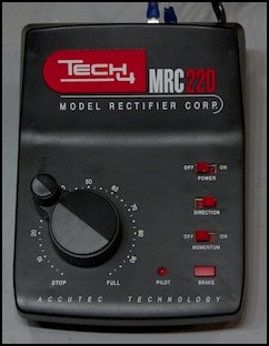
MRC Tech 4 220
Peak Voltage: 19.3 V
Amperage: unknown
Accessory: 18.0 V AC
Pulse Type: 60 Hz half-wave ripple on rising DC, artificially shaped or capped
After a comment on the JNS Forum (c. 2011) about a more modern MRC Power Pack, the Tech 4 220, being rated for 23V output, I decided to check one of those out as well. The following is a slightly updated version of my original testing report on it, using my old oscilloscope. When I re-did my tests in 2013 I couldn’t find this pack, as I’d managed to pack it away somewhere “safe”. I did finally locate it, but haven’t found time to re-test with the new scope.
The marketing materials on the box imply that the power output is actually scaled based on load, not simply on the throttle setting, in something akin to a DCC BEMF decoder. Other comments I’ve found online seem to agree: the “Accutec” feature is effectively a BackEMF-based feedback control similar to that found on DCC decoders. This would raise the voltage for a given throttle setting as load increased (due to more cars or grades). I didn’t have any way to test this, as I was evaluating on level track with a single locomotive as the load.
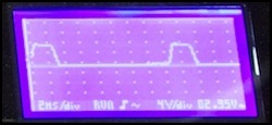
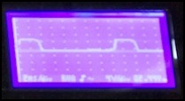
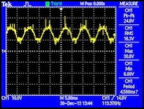
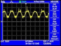
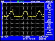
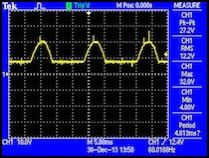
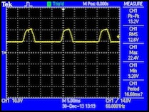
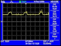
MRC 220 at 1.7V, 3V and 5V
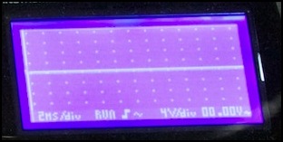
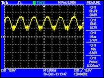
MRC 220 at 10V
Using a typical modern N-scale locomotive, I saw a maximum voltage of 19.3V, and 12V was reached with the throttle set to just 62.5%. As N-scale locomotives are in theory designed for 12V use, this makes using such a power pack a bit risky. It could cause overheating of the motor, leading to damage, if accidentally set to maximum for an extended period (or if pulling a very heavy load and the Accutec feature raised the voltage to that level), or potentially even failure of the motor windings due to excessive voltage, although that seems unlikely as the motors are probably designed to survive exposure to 16V with a safety margin.
The MRC 220 is clearly generating artificial pulses every 16 milliseconds (once per cycle) atop a flat DC output, similar to what the Control Master II was doing. The pulses appear to get closer (a little) as the throttle is advanced, but I’m not sure if that’s real or just an example of how poor my scope is. In other words, at base this is a half-wave output similar to ripple, although the waveforms appear to be at a minimum artificially capped, and could be entirely artificial waveforms. The pulse height is around 8V at the lowest setting, and reduces as the throttle turns up, but goes away entirely once you get to a moderate throttle setting. That’s an improvement over the CM II, and exactly how you’d want pulsed power to work, and it’s an example of what level of control even relatively low-cost modern power systems can provide.
If you have one of these and use it to run trains at a reasonable speed you don’t need to be concerned, as it’s going to be putting out the voltage it needs to run the train, nothing more. Still, if you’re in the market for an N-scale power pack, I wouldn’t recommend this one due to the risk that it could be set to full and cause damage. That said, if you’re careful not to turn it up all the way it’s a fine pack.
As for the accessory output, this is probably the direct output from the internal transformer, before it is rectified to DC for the throttle. Thus you get a normal AC wave (likely with some distortion if a train is running and drawing power erratically from the transformer). The value measured is thus a normal 60 Hz RMS AC voltage. And 18.0 isn’t unreasonable if rectifying that creates up to 19.3 V for the trains.
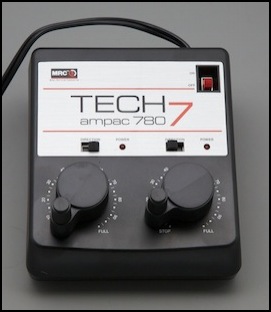
MRC Tech 7 780
Peak Voltage: 14.5 V
Amperage: 0.7 A (claimed)
Accessory: 14.8V AC
Pulse Type: adaptive
The Tech 7 series is MRC’s latest (as of early 2014, and still current in 2016), and the 780 is slightly different from the other models. It has a lower maximum voltage (14.5 versus 15.5) and two throttles (“cabs”) in one case. It’s also somewhat lower in power, with its 20 VA capacity divided into two 10 VA halves (per the documentation, each of the two cabs is limited to 10VA), where the other models are rated at 20 VA for a single cab.
I bought one to use for the outer (express line) double-track on my layout. It’s a relatively simple system, with just a throttle knob and direction switch for each supply, and a master power switch. Each of the power supplies has its own pair of output terminals. The circuit breakers are internal, and self-resetting. In terms of features, it claims “Accutec”, which is MRCs version of Back EMF-sensing voltage adjustment to raise the voltage when climbing grades or otherwise dealing with an increased load, and good “slow speed performance”
Note: as of 2016 MRCs online specs still show 14.5 VC as peak DC, but rate the accessory output as 18.5 VAC. I suspect this is a typo as the other models also list 18.5 VAC, which makes more sense for them given that their DC outputs go up to 23 VDC.
I have not yet tested this pack. I really ought to.
Kato
Peak Voltage: 18 V (peak, no load)
Amperage: ~1,000 mA (approximate)
Accessory, DC: unfiltered ripple, 15.9 V (RMS?), 22.4 (peak DC)
Pulse Type: 120 Hz full-wave ripple
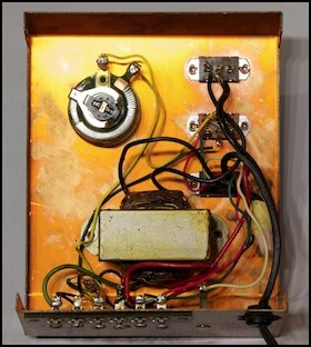
When I switched from HO to N, I decided I needed some N-scale power packs, and ended up buying three of the Kato USA ones designed for use with Unitrack. My three Kato power packs are all identical. These are designed to be used with Unitrack, and have a socket for Kato’s standard track feeder rather than screw terminals. Output voltage is nominally 12V, but actual measured voltage was 14.8V under load. As you can see from the scope trace below, 15.9 is about the RMS voltage for the half-wave signal; actual peak voltage is 22.4V.
Note that these are U.S.-spec Kato power packs. These use an external transformer, so even if the power pack is identical to those sold in other countries, the output voltage may be different depending on the specific transformer used. In particular, while the pack is labeled “15V 1.5A” on the input, and the transformer is labeled the same, the actual output of the transformer is 17.0 V AC RMS per my multimeter. I own three Kato packs, and measured the AC supply from a second as 16.5 V, so this isn’t a case of one off-spec power pack.
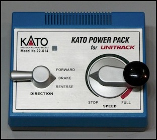
Kato Power Pack (U.S. version)
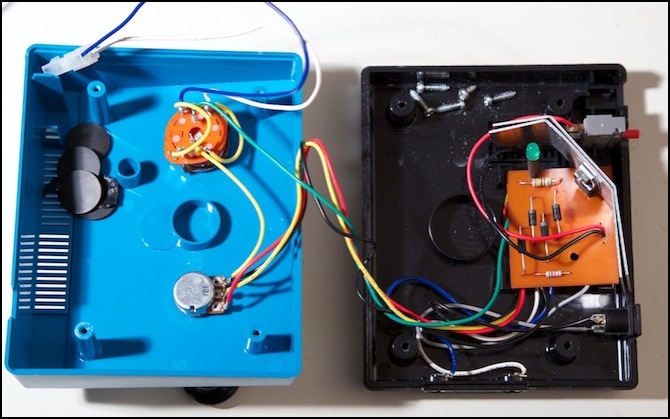
Inside the Kato Power Pack
Kato’s approach is rather simple: they don’t filter the input AC, they only convert it to DC. So what you get is a DC voltage that goes from 0 to whatever the throttle is set at and back to zero on an 8 millisecond cycle. In other words, you get “pulsed” of power at a frequency of 120 Hz.
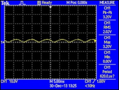
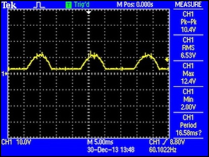
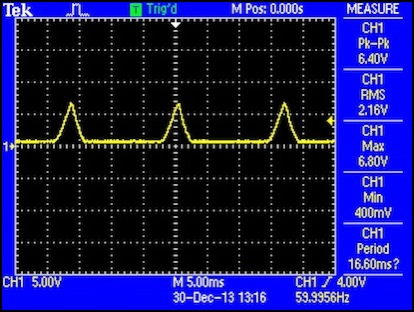
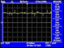
Kato, lowest speed, 20% throttle
Kato, at 50%, 70%, 100% throttle (with loco)
Kato uses a simple full-wave ripple, without filtering. A transistor circuit is used to reduce the voltage of this for the track, with the raw voltage being passed to the accessory output. There does appear to be a DC component at higher voltages, but like the MRC 501 this is simply a floor, and never rises to eliminate the peaks of the pulses at higher throttle settings. Voltage is also surprisingly high, with peaks around 20V (not counting noise), with RMS reported as 15.8 V, at 100% throttle. Kato’s throttles are marked with a green band that ends at about 75%. Measured there the peak was still about 18 V, although RMS voltage was reported to be 13.7 V.
I had measured one of my other packs separately using my RRampMeter, which reported track voltage as 14.7 V (probably an RMS voltage).
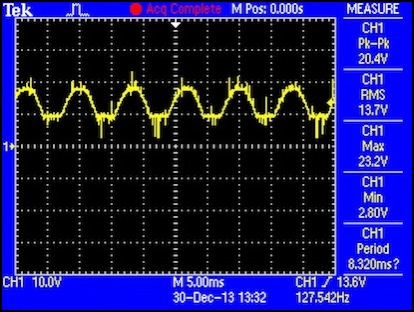
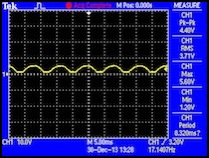
Kato at “red line” 75% throttle, with loco
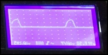
I also measured the “12V DC” accessory output, and to no surprise found it to be the base ripple, with a peak of 22 volts and a 15.9 V RMS reading. That’s remarkably high for a 12V output. It won’t matter for Kato turnouts, but don’t hook any LEDs up to this!
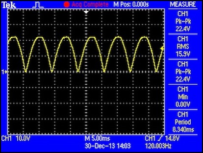
Kato “12V” accessory output: 22.4V peak, 15.9V RMS
I am a bit disappointed at this result, although not surprised since this is the same thing I measured three years ago. It could simply be that they aren’t compensating properly for the higher-voltage electrical grid in the U.S. (which would explain why the “15V” transformer puts out 17 volts). And if the RMS reading is correct, the voltage actually in use at the loco is reasonable if you stay in the green zone of the throttle.
If I was really bothered, I could substitute a separate external transformer that really did put out 15V AC RMS, and be pretty close to what I needed (a 14V one might be better). Since Kato uses a standard 2.1mm power jack, typical of many external transformers, connecting a substitute would likely be easy to do (at worst I’d need to solder on a different plug, but they’re easy to find from electronics supply stores).
Tomix
N-400:
Peak Voltage: 10.5 V (unloaded) / 10.4 V (loaded)
Amperage: 400 mA
Pulse Type: constant voltage (not pulsed)
N-1:
Peak Voltage: 11.3 V (unloaded) / 10.2 V (loaded)
Amperage: 500 mA
Pulse Type: constant voltage (not pulsed)
Note: these are Japanese-spec power packs, and I operate them on 100V AC (not the usual U.S. 120 V power) using a varistor power supply. All results reflect that usage.
Finally, I bought a couple of Tomix packs designed for use with smaller light rail trains and their FineTrack sectional track, for use on my Urban Tram Layout. These are designed for use with Tomix’s FineTrack sectional track and have a socket (different from Kato’s) rather than screw terminals. The two Tomix packs are rated at 500mA and 400mA (the latter with a nominal voltage of 9V, not 12V). In practice the N-400 (rated for 9V) put out 10.5V unloaded, and 10.4 volts running a small tram. The N-1 (rated for 12V) put out 11.3V unloaded, and 10.2V running a tram.
These are probably not very representative of current Tomix DC packs, as those all seem to be 12V models (like the N-1) but with “constant lighting” AC superimposed on the DC signal. It’s not clear to me if there are other differences.
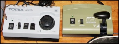
Tomix N-400 (left) and N-1 (right)
Note: the N-1 has been discontinued by Tomix, replaced by the 1 Amp N-600, which uses a knob rather than a lever. The N-400 is only available in their mini-rail starter set (item 90093), and not separately.
Conclusion
My conclusion from this is that I’m glad I’ve decided to use DCC, as I have a lot more control over the voltage supplied to my motors with that (now that I’m using a DCC system that has an “N-scale” voltage option). None of these packs appear to really meet the requirements of providing 0 - 12 Volt DC over the range of the control, meaning that top speed will be reached using a relatively small range of the throttle’s rotation. The MRC 220 was close to providing the needed range for HO scale, but still a bit on the high side.
The Kato pack is putting out an uneven voltage, which is likely good for running trains at lower speeds, but isn’t really “right” for higher speeds. That said, the low-speed control was good, and there was clearly no undesirable heating occurring at even 10 volts (which is probably as fast as you’d run anything other than a Shinkansen at full tilt). It’s an acceptable N-scale pack, but fell short of what I’d expected to see from a specialist N-scale company with their reputation for quality.
And I’ve confirmed that the “conventional wisdom” that power pack accessory outputs are only good for running incandescent bulbs and insensitive turnout motors is quite true: these things are miles off-spec, and could do real damage to anything sensitive connected to them. Invest in a good regulated 12V DC transformer for sensitive accessories (you can find them for US$6).
One final consideration was how well these would work for stall current determination as I move to DCC. That’s less of an issue now, as for the most part I can test on my bench with a regulated 12V supply if I really need to check stall current, and most of the time I am using decoders rated 1 amp or higher, and none of the motors are likely to need more.
Still, the MRC 220 pack is probably the best for measuring stall current, since its waveform at full or near-full voltage is much closer to a straight line (constant voltage implies constant current, and a more accurate reading on the RRampMeter). However some care is needed to set it to a throttle setting that output a safe voltage (12-16 volts).
