


Control Bus
A control bus, or layout control bus, is a two-way communications system that ties devices related to the layout together or to a central management station. DCC itself isn’t a control bus, because it’s essentially a one-way system despite some minor feedback capabilities. While a control bus is often used to connect a computer to the layout, a bus doesn’t have to include a computer, and many are part of DCC systems without computers. A bus can simply be used between devices, such as occupancy detectors and signals or handheld throttles and command stations.
Also, while a “control bus” is different from a throttle-only “cab bus”, most current control bus systems started out as the latter, and the dividing line between the two is often rather arbitrary. What I’ll cover on this page are systems capable of bi-directional communication, which support devices other than or in addition to throttles (many will also support throttles). The most common devices after throttles are occupancy detectors, turnout (track switch) controls, and lineside signals, but they’re not the only ones.
Since one key function of a control bus is to be extensible to support new things, and since a lot of those “new things” are likely to be based on Arduinos (or similar small embedded processor devices) I’ve paid particular attention to calling out the amount of current support for Arduino, either in the form of physical shields or interface libraries. Unless you’re an electronics hobbyist, or are going to buy pre-built things from one, this probably doesn’t matter to you. But it is a good indicator of how “open” the system is to use by third parties.
One of the most important devices for use on a control bus is the Occupancy Detection sensor, and I have a separate page covering those.
There are a wide variety of bus systems in use today, some multivendor, some used only by one company. Several of these have been around for decades, and are well-proven. The NMRA is shaking things up by working on a standard for a control bus, recently renamed Layout Command Control (LCC). It remains to be seen if this will be as revolutionary as was DCC, but it could be.
Riding the Bus
The word “bus” gets tossed around a lot in electronics, meaning different things in different contexts, so what does it mean on a model railroad? Essentially it means a communications system by which information can be exchanged between multiple (more than two) devices. If that sounds a lot like a computer network, it’s because the two are very similar. In fact many simple computer networks are in essence bus systems. However model railroad bus systems are typically a lot simpler than computer networks, to keep the cost of individual devices as low as possible.
Several important technologies go into a bus. First, there’s some kind of physical standard that defines the type of wire (gauge, number of conductors, twists per foot, etc) and connectors used. Then there’s an electrical standard that defines how the wire is used (voltage, and various technical details like bit speed and synchronous vs asynchronous clocking). In many cases, companies have used existing standards for serial connections used in the computer industry. But none of that explains how “messages” move across the bus. This requires some standardized format, called a “protocol” that groups bits into structured information, like commands and data to be passed. The protocols used are almost always proprietary, meaning that one company created them, and either doesn’t let someone else use them, or licenses them to other companies. Finally, there is usually more than one protocol in use. A basic one allows devices to be identified and messages passed between them (this is sometimes called a “network layer” protocol). Then the meaning of messages specific to a given application need to be defined, such as “turn device N on” or “sensor M reported status X”. This is sometimes called an “application layer” protocol, and it uses the network layer to move its messages around.
A truly “open” system would use standards for the physical and electrical aspects that had no restrictions on their use, and either an existing or new protocol that was published and similarly unrestricted. More common are published standards where patents or other restrictions may exist, but licensing is easy and relatively inexpensive. Many common technologies, like Ethernet and WiFi, use this kind of standard.
To make a bus work, each device on it must have a unique identity (called an address). This may be assigned at the factory, chosen automatically by the devices, or entered manually by the human who bought the system. Often there are also special addresses used to mean “send to everyone” (broadcast address) or “send to everyone who cares about X” (multicast addresses). A device will normally listen for any command sent to either its own address or the broadcast address, plus the address of any multicast group it is a member of, and ignore all other messages on the bus.
In model railroading, the idea of having a general-purpose control bus evolved out of earlier “cab bus” and “feedback bus” systems. A true bus supports communications in both directions. But there are a number of things called “busses” that are one-way. A “cab bus” is a one-way system from a handheld control unit to the actual electronics providing power and control to trains. Similarly, a “feedback bus” is a one-way system for an accessory to report status back to the control station.
Almost all bus systems to date have been proprietary systems, meaning that some protocols were undocumented or available only under a restrictive (and sometimes expensive) license. And often patents or other protections prevent anyone from making compatible equipment at all, or without paying a license fee.
The NMRA, which defines standards for model railroading in North America (and to an extent elsewhere), originally did not define any standard for a cab bus, feedback bus or control bus, so a number were created by companies for their own products, and some of these came to be used by other companies as well. In 2008 the NMRA finally set out to define a standard control bus, now known by the name of Layout Command Control, or LCC, but it’s not really quite ready for prime time yet. Today there are a number of competing solutions, some of which have more compatible products available, and more effective capability, than the NMRA-standard solution. That may not be the case in five years, or ten, but it is right now. One strength of the NMRA’s ultimate solution is that it should be based on accessible technologies (and that certainly seems to be true of what’s been done so far). That doesn’t mean that there won’t necessarily be licenses involved (connectors may be patented by someone, for example, or specialized chips needed that aren’t practical to re-create, so they’d have to be purchased from a manufacturer), but the costs for these so far appear to be nominal and not enough to prevent smaller companies or even hobbyists from making compatible products.
Bus Technology
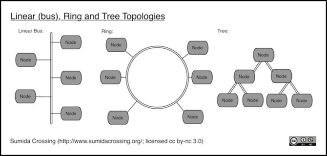
A bus is typically created by running wires between devices and panels where portable devices (like hand-held throttles) can be plugged in temporarily. If these are in a single row (each device or panel connecting to only two neighbors) but the two ends aren’t allowed to connect to each other this is called a linear bus or a “daisy chain”. If the two ends can connect, then it’s called a “ring”. If each device can connect to three or more neighbors, but no connection is to loop back to an earlier device, then it is called a “tree” because of the way a diagram branches out from one point to many.
Bus systems used for model railroading were developed using two-wire serial technology, partly because this was well understood and the required components were already mass-produced and inexpensive. Most control bus systems for model railroad layouts still use a simple two-wire serial line, but with additional wires added to carry power and ground, so smaller devices don’t need separate power supplies. Some have additional wires for other purposes. Although the RS-485 serial standard is used by many of these, the way it is used differs (the software or “protocol” sent over the serial wire) so different control bus systems are not compatible with each other even when both use RS-485.
Additionally, computers don’t use RS-485, but other serial standards (such as RS-232), and this has led to some hybrid systems that can work with either, as well as to some designs that require a device to adapt computer serial interfaces to the bus’s preferred form. This is possible because the actual message (the protocol) is separate from the serial hardware standard (RS-whatever, USB, wifi, etc). As USB has taken over from RS-232 serial ports on computers, such adapters have become more typical. There are also similar devices that allow wireless devices to connect to some of the serial-based systems, although these are a little more complex.
RS-232 isn’t technically a bus. It’s a two-ended device to device link rather than a shared communications system used by multiple devices. However, if each device has two RS-232 interfaces, it can pass messages from one to the other, resulting in a chain of devices. That’s not a “bus” in the technical sense, but it works effectively the same for layout control or similar applications. And systems made using point-to-point serial links like this are sometimes called bus systems.
Bus systems of any kind typically have limits on the number of devices or the total cable length (or both) or restrictions on how devices are connected to each other. One solution for larger systems is a type of device that connects two (or more) separate bus systems together. Depending on how they work, these are called “repeaters” or “bridges”.
A “gateway” is similar to a bridge, except that it can connect two different kinds of bus systems, or a bus to some other kind of network. One fairly common kind connects wireless devices (such as cord-free walk-around throttles). There can also be gateways to allow devices on a Wi-Fi network (such as a smartphone) to communicate with devices on a command bus.
Types of Control Bus
A control bus is by definition a two-way system, allowing both control and reporting. However, a number of similar systems are “feedback bus” systems, which only allow devices to report status back to a central location. Those can still be useful if you do control in another way (e.g., using DCC accessory decoders). I’ll reserve “control bus” for bidirectional systems, but cover both types on this page.
A Cab Bus is yet a third type, having control but not necessarily feedback functions. Cab bus systems are typically proprietary and only support one kind of device: a hand-held throttle, although sometimes a more general control bus is described as a cab bus. I won’t cover strictly one-way cab bus systems here.
Additionally, a control (or feedback) bus can be “centralized”, requiring a computer or command station for its operation, or “decentralized”, allowing devices on it to communicate directly.
Bus Examples
There are a number of control and feedback bus systems on the market. Some of these are proprietary and specific to equipment made by one vendor, while others are either fully open standards or proprietary standards that allow third-parties to manufacture devices for them (possibly with the payment of a license fee). Note that control bus systems that allow for third-party products may still have limits on how devices work together. For example: even if two different manufacturers use the same bus, the command station from one may not work with a hand-held throttle made by the other.
C/MRI
The Computer/Model Railroad Interface (C/MRI) was invented by Bruce Chubb in 1985, not long after there first were computers to connect to model railroads, and is still in use today. In many ways it is much simpler than a modern control bus, but that isn’t really a problem. And about the only thing it doesn’t do is act as a cab bus (and somebody, somewhere, probably uses it as one; one of its great strengths is that it is easily used by electronic hobbyists).
As the name implies, C/MRI requires the use of a computer, and in fact all devices on the bus communicate only with the computer. If two devices need to work together (e.g., an occupancy detector and a crossing gate motor) the computer must mediate between them. Everything other than the computer is treated as a simple on/off wire (although multiple wires can be used together to manage more complicated things). This makes C/MRI an excellent system for remote control panels and devices like turnout (track switch) motors and lineside signals.
C/MRI is based on the RS-485 serial standard. It uses a “RS-485 Converter” to connect to a computer, and runs between “SMINI” devices (as well as the larger SUSIC and older USIC equivalents) on the bus. Other devices, such as simple occupation detectors or the SMC for turnout control, connect to the SMINI. The converter is technically optional, and only required when daisy-chaining multiple devices, so you could start without one for your first SMINI (assuming you have a serial interface on the computer) to limit costs. It is recommended, however.
Each SMINI (or equivalent) must have a unique address set manually at installation by setting small DIP (dual-inline package) switches on the board.
One major drawback is that the company’s “product”, aside from electronics, is the design of C/MRI, which means that documentation is sold in book form rather than being freely available online (although you can find a lot of information by Googling around, you really need at least some of the paper documentation). As of September 2013 the third edition is up to three volumes at US$35 each, with a fourth planned. It’s a small part of what you’d ultimately pay for the whole system (regardless of whose control bus you use this stuff ultimately isn’t low-cost for a layout of any moderate size), but this makes it hard to evaluate the details before committing to the technology.
C/MRI is supported by the open-source JMRI program, which treats C/MRI inputs as “sensors” and outputs as “turnouts” or “lights”. However, I haven’t been able to find any indication that C/MRI is supported on Linux computers.
Since devices communicate with the SMINI in a very simple manner (essentially an on/off state), it’s very easy to create something using a device like an Arduino (or even just a simple circuit) that communicates using one or more “bits”, with each bit being a C/MRI input or output. Here’s an example of someone using an Arduino to control a crossing gate, with a simple up/down signal from C/MRI connected to one digital pin on the Arduino.
In general, Arduinos lack the hardware to directly participate in C/MRI (i.e., you still need to buy an SMINI), but there are one libraries available (like this one) for those that do. There’s also a specially-built Arduino clone that does support it (see this PDF).
CTI Train Brain
CTI Electronics makes a proprietary line of remote control and sensing modules known as “Train Brains” that are used to create a control bus. These include the relay and transistor-based “switch” modules for controlling things, and a variety of detection sensors (including magnetic, RFID, Infra-Red and optical, as well as the more common current-based ones). They also make a throttle that can be used with this system.
CTI provides their own software running on the computer. This is apparently free if you buy their circuit boards (downloadable as a trial version with an unlock key), but available only for Windows. If you use their software, all that is required to connect a computer is a small circuit board called a “diplexer” (US$7 and included in the starter kit) for computers with a serial port, or a “USB Bridge” (US$30) for computers with USB.
In addition both RR&Co and JMRI support CTI via a more sophisticated interface, called the Acela (US$40), which is sold in both serial and USB versions. This board does not appear in their catalog, but is hidden away on an application note; JMRI says only the serial version is available as of September 2013.
CTI uses four-conductor flat cables with RJ11 (telephone) connectors. The Train Brain units must be cabled as a ring, i.e., each module is cabled to the next, and both ends connect to the board providing the computer interface.
There do not appear to be any third-party manufacturers of compatible modules, nor could I find any Arduino-based hardware or libraries.
Digitrax LocoNet
Digitrax’s LocoNet (see also my page on LocoNet for more info) is used not only by them, but by a number of other companies under license. This means that there is a fairly rich variety of LocoNet-compatible devices on the market. While LocoNet is often associated with Digitrax’s DCC systems, it can be used independently of them (i.e., you don’t need to own a Digitrax command station to use some kinds of LocoNet devices).
LocoNet uses six-conductor unshielded flat-cable wiring with RJ12 connectors. While most devices have only two LocoNet connectors, it can be wired in a tree structure with some limitations. A LocoNet bus can have up to 32 devices on it (one document says 40), although they recommend limiting each to about twenty. A limited form of the standard (LocoNet Personal Edition) is available online to non-commercial hobbyists, but the full standard is not.
Loconet uses a proprietary signaling method similar to that of Ethernet, but at the much lower bit rate of 16.67 Kbps. that may not sound like a lot compared to some other systems, but it is sufficient for what it does and it makes the electronics both simpler and cheaper than they might otherwise be. Signals on the wires are “differential”, meaning that one wire is positive when the other is negative. This helps to limit electromagnetic emissions. It also simplifies wiring, because you don’t need to worry about which wire in the cable is “transmit” or “receive”.
Digitrax makes a repeater (originally the LNRP, today the LNRP Xtra) for building larger or longer LocoNet systems. The also make gateways supporting their wireless (InfraRed and radio) hand-held throttles. Smartphones can’t directly connect, but can connect via JMRI.
The extra two wires in the LocoNet cable (after the two power and two serial wires) carry a copy of the DCC signal when LocoNet is used with a Digitrax or compatible command station, so that boosters can be connected to the command station via LocoNet with no additional wiring. The signal format of these wires appears to conform to the NMRA’s standard for connecting command stations to boosters (S-9.1.2, PDF), and is compatible with Lenz boosters as well, although the connectors are not. The signal on the extra two wires is not always passed along by LocoNet devices, so boosters should normally be the first devices on the bus after the command station.
There is Arduino support for LocoNet in the form of the Embedded LocoNet library, which is part of Model Railroading with Arduino.
Note: Loconet is *not* based on the RS-485 serial standard, despite an earlier statement to that effect here. I’m not sure where that misinformation came from, but I’ve fixed it. Thanks to one of my readers for pointing out the error.
Lenz XpressNet, X-Bus and the RS Feedback Bus
Lenz created DCC, and their XpressNet is the granddaddy of modern control bus systems, dating from 1993, but it is mainly intended to be used as a high-speed cab and control bus, not a general communications bus. Lenz also has a separate Feedback Bus for devices, like occupancy detectors, that need to send infrequent information and which do not require instant attention.
XpressNet is actually version 3.0 of their X-Bus, and is a significant change in the software protocols from earlier versions, while remaining compatible with them. Like LocoNet there are other manufacturers making XpressNet-compatible devices. Unlike LocoNet, XpressNet requires a Lenz command station to work because it is a centrally-managed network of devices. At heart it uses the standard RS-485 serial protocol, and the specifications are published online, making third-party construction of compatible devices relatively easy.
XpressNet uses four-wire twisted-pair wire arranged in a tree structure, with RJ connectors (some systems and manufacturers have also used 5-pin circular DIN plugs). There is a limit of 32 devices, including the command station, on a bus. The length of any single segment between devices is limited to about 1,000’ (305 m).
XpressNet requires the use of devices that precisely implement RS-485, and does not allow ordinary serial interfaces (RS-232 or USB) to connect directly to it, instead a computer interface device connects to the computer’s serial interface and to the XpressNet. Lenz sells several different models of these. Addresses on an XpressNet are simply numbers from 1 to 32.
XpressNet operates at 62.5 Kbps, but each device must wait to be polled by the command station before it can send anything. This provides for an even distribution of bus capacity to devices, but isn’t very efficient if most of the communications is happening between a couple of devices. However the bus speed is sufficiently fast, and the size of messages transmitted relatively small, that this is not likely to pose a problem.
Lenz’s Feedback Bus uses two wires attached to screw terminals on the command station, with devices (such as the LR101 feedback encoder) connected to these wires in parallel. There can be up to 64 of these (newer documentation says 128). The terminals are labeled “R” and “S”, so this is sometimes referred to as the “RS bus”. There are third-party devices for the Feedback Bus, such as the LDT RS-8, containing eight occupancy detectors in one case.
There does not appear to be anyone doing shields or software to interface an Arduino to the Lenz Feedback Bus. I found a number of hobbyists who had started work on Arduino shields or libraries for XpressNet, but none appear to have been completed.
MERG RPC
MERG is a UK organization that’s been around for more than 45 years. RPC, the Remote Panel Control System, was an early control bus. And it’s still in use today. Like others, it is based on RS-485, but it can also use RS-232 for simple single-device applications.
MERG CBUS
A more modern offering from MERG, and at one time a contender for the NMRAnet (now LCC) standard, is their version of a CBUS-based protocol. LCC incorporates some CBUS event identifiers, which would make a gateway between the two systems possible, but I’m not aware of one offhand.
The specifications are available for download from their site.
MRBus
The MRBus (mrbus.org) is a serial-technology bus designed for use with microcontrollers such as the Arduino. It’s based on RS-485 serial chips, but is not RS-485. Rather it is a shared peer-to-peer network, similar in function to Ethernet, but at much lower speeds. Bus speed in practice is estimated to be around 28 kbps, so it is relatively slow compared to newer bus designs (e.g., LCC on CAN bus wiring operates at about five times the speed). The technology was originally created for a University solar car telemetry bus (oddly reminiscent of LCCs origins from the automobile CAN bus standard; apparently cars and model railroads have much in common, who knew?).
There’s an Arduino-compatible library available for it, licensed under GPLv3 (not my favorite open-source license, I must say, but a common one). This is also a reference implementation for PIC microcontrollers, for those who want to design their own boards.
Although MRBus has existed since 2001, it does not appear to be widely used. And the website appears to have been last updated in 2012 (as of 2017), so LCC may have killed it. There is, however, one manufacturer of commercial systems that uses it: Iowa Scaled Engineering, which makes a variety of stand-alone nodes, plus a shield for Arduino use.
And the focus on Arduino means that I could make my own devices relatively easily, while also buying commercial products (from one company).
NCE Cab Bus
NCE has been making DCC products for over twenty years (since 1993). Their current “NCE Cab Bus” uses six-wire unshielded twisted-pair wire with RJ-12 connectors in a daisy-chain arrangement, which supports up to 63 devices (simple wiring panels aren’t addressed, but the throttles that plug into them are). Device addresses are set manually at installation time by setting small DIP (dual-inline package) switches on the board to select an address from 1 to 63.
This isn’t quite as functional as C/MRI as a control bus, since it seems to lack a good way to control simple (non-DCC) output devices.
NCE’s bus requires their DCC command station, which also serves as the interface between a computer and the bus. The bus is a daisy-chain between front-of-layout panels with modular jacks for connecting hand-held throttles (which NCE still calls “Cabs”) as well as other devices, such as the AIU, which provides a set of one-wire on/off input-only sensing lines.
Devices for use on the cab bus seem to be fairly limited, and only made by NCE. I’m not aware of any Arduino support for the NCE Cab Bus, but it is possible to use an NCE USB adapter to connect an Arduino or Raspberry Pi to one (see this site for an explanation).
The NCE Cab Bus is supported by the open-source JMRI program, which treats AIU inputs as “sensors”. It can also send commands to turnouts (track switches) treated as DCC accessory decoders, but this is apparently done via DCC; the turnouts do not connect to the Cab Bus.
LCC, NMRAnet and OpenLCB
Names change, and what was NMRAnet during the early development process has been renamed (as of 2015) as Layout Command Control (LCC) to highlight its intended use as a complement to DCC. Where DCC is for controlling trains, LCC is for managing a layout, including some functions that could also be done via DCC accessory decoders or feedback systems (like throwing turnouts or detecting trains), but is a more general control and reporting structure. And while it is designed for communicating between stationary devices, it can communicate about trains (e.g., used as a cab bus between a handheld throttle and a DCC control system).
As of early 2016 commercial products based on the standards have begun shipping, and I’ve added an LCC Products page to note the ones I find interesting.
Some history: In 2008, the NMRA began work to standardize a control bus to "manage and control devices that are independent of train control on a model railroad layout”, which came to be known as NMRAnet. This led to the development of a set of standards known as OpenLCB outside of the NMRA by one group of modelers, to be proposed to the NMRA (there were competing proposals, including one by Lenz based on XpressNet as well as MERG’s CBUS). As open standards, both the NMRA and OpenLCB publish their standards online.
There was a bit of drama in the early days, but in August of 2012, the NMRA adopted standard S-9.7.1 NMRAnet Physical Layer (since renamed CAN Physical Layer). as well as an accompanying technical note TN-9.7.1, the first (of likely many) of the NMRAnet standards. A physical layer standard just defines what kind of wires and connectors to use, but it was an important start.
In March 2015 the NMRA began a six-month public comment period on a new set of draft standards and associated technical notes (also added to the NMRA’s Standards page) covering several data-exchange standards. These standards don’t address all details of how an application would use the communications system, but provide the essential foundation for later standards that do, or for independent development of compatible applications using the same basic electronics. And some basic application functionality (like reporting events) is defined. At the same time, the NMRA changed the name to Layout Command Control (LCC), emphasizing the purpose of the network, rather than the network itself, and implying the relationship with DCC.
One of LCC’s innovations is that it is designed to allow “node discovery”. That is, if you use a central command station or computer, it can find nodes attached to the network without needing to be told about them. This is vital for “plug and play” operation. It also allows for simple, feature-reduced nodes, which may be more economic to implement in stand-alone devices (e.g., a lighting controller inside a ready-made building).
As an example of what’s missing: there’s no sensor/actuator standard that I can see. You could make one from events, but that’s just the foundation. What this means is that company A’s train detector can’t talk to company B’s crossing-gate actuator, without a human associating the two. It’s not a complex process, but it’s not quite plug-and-play yet. We’ll need more standards before this is ready for “under the Christmas tree” users. And anyone who doesn’t think that’s important has probably forgotten how they got into the hobby in the first place.
OpenLCB has gone quite a bit further than just writing things, and a number of devices based on OpenLCB standards were available originally that could do a number of useful functions. As of 2015 these all seem to have gone out of production, but manufacturers are reported to be working on the first true LCC devices (and the first have shipped as of early 2016). It’s important to understand that OpenLCB is not LCC but that OpenLCB is the foundation of LCC. What has emerged and will later emerge from the NMRA may or may not be compatible with OpenLCB devices purchased earlier. Compatibility is likely, but not assured.
LCC uses the CAN (Controller Area Network) 2.0 standard, with unshielded twisted-pair wire (a minimum of four wires, or up to eight) with RJ45 connectors. This is the same wire and connectors used for Ethernet, so they are readily available at low cost. Unlike most other control bus systems, the underlying technology is not a simple serial line, but a control bus designed for industrial control applications and found in, among other things, most modern automobile control systems. Although it requires moderately sophisticated electronics, these are based on chips mass-produced in very large volumes, so costs are relatively low, and the system is designed to provide reliable operation in a fairly hostile environment (inside an automobile) and thus should be reliable in a model railroad.
Despite its use of Ethernet cables, LCC is not Ethernet. It operates at a rate of 125 Kbps, while Ethernet uses 10 Mbps or higher. There is a limit of approximately 30 - 48 stations on a single CAN segment, but each station reduces the effective maximum length of the bus, so 48 would only be possible with a bus 47 feet in length with one foot between each station (and formally, the limit is 30 nodes and some chips may not allow more). At a minimum, cable must have two twisted pairs and be compatible with “Category 3” (Cat3) Ethernet standards (meaning any commercial Ethernet cable can be used, but ordinary telephone wire, which is Category 1, cannot). Preferably, cable with all four twisted pairs, compatible with “Category 5e” (Cat5e) or a higher-numbered standard, should be used to ensure support of future capabilities (two of the extra wires are used for power, the other two are reserved). However, the standard does not require the unused wires (some simple Ethernet cables omit extra wires).
Note: with Ethernet cables, higher numbers are always compatible. Thus a Cat5e (or Cat6) cable can be used anywhere a Cat3 is required. The reverse is not true: if Cat5e is required, substituting Cat3 may work some of the time, but may prove unreliable or not work at all. LCC requires Cat3, so any Ethernet cable can be used, as there are none below Cat3.
LCC uses standard CAN 2.0 network protocols (and allows older ones to co-exist) so it can use off-the-shelf CAN hardware. As a result it supports (in theory) the use of existing repeaters and bridges, with some limitations, to get around the limits on a single segment. A repeater can extend overall length (but timing limits will still impose a maximum). A bridge can extend overall length and avoid the timing limit, but may be incompatible with capabilities based on “RTR frames” (LCC does not use RTR so this only matters if the same CAN network is used for something else). Bridges can be used to connect media other than a CAN segment (such as wireless links), but do not change the data format, and for that reason are not compatible with other networking systems (e.g., Wi-Fi). Gateways are similar to bridges except that they allow for use with other network technologies, such as Ethernet, Wi-Fi or IP networks. An LCC Gateway needs to be designed to work with LCC, so any interconnection with Wi-Fi (or Ethernet or other networking systems) will require a new LCC-specific device.
A CAN Network can support up to 4,096 nodes (this would require over 100 linked segments). A practical limit is smaller, but still likely over 1,000 nodes. However a single segment has a practical limit of less than 48 nodes before it needs to be broken up with a repeater (and right now nobody makes those specific to LCC, and existing CAN versions are industrial-grade and cost several hundred dollars).
LCC supports bus-powered devices, although the total power is very limited. This does allow some simple things, like signals, to be part of an LCC bus without needing their own power supplies.
There is a considerable amount of Arduino support for OpenLCB:
- There are libraries available at Model Railroading with Arduino. (these aren’t complete, but they’re a start)
- CAN shields are available. These include the chips for connecting to the actual bus (see the Suppliers page).
There are also other projects (google for them) if you are up to ordering custom circuit boards and building what are in effect electronics kits.
S88
Technically, S88 is a feedback bus with multivendor support (from ESU, Märklin, and Viessmann, as well as OpenDCC). It can apparently also be used as a Cab Bus (at least, ESU appears to use it that way although I may be misreading that). Most of the documentation I could find on S88 was in German, making it a bit of work to understand. However, there is a set of English-language pages about it as well as some information on the OpenDCC site in English.
S88 is a very simple serial communication system, and vulnerable to disruption by electrical noise as a result. Use of twisted-pair cables designed for computer networks (i.e., Ethernet cables) can avoid some of these problems. Unfortunately, not all modules use Ethernet-compatible RJ45 connectors. In 2008 a new standard, S88-N, was adopted (well, by at least the two authors; I couldn’t find anything indicating a standards organization was involved, although it does appear to have multivendor support). This specifies the use of Cat5 RJ45 cables and connectors (which are standard low-cost Ethernet cables, although more expensive than Cat3). Even this can take incompatible forms, as the accessory power supplied on the bus can be either 5V or 12V.
S88 is apparently a daisy-chain, but there are “data switch” modules (LDT DSW-88-N-G, €50 or ~US$66) that can split it, forming a tree structure (these may be repeaters; I can’t tell).
It appears that S88 is implemented slightly differently by each vendor (even the signals on the wires differ between vendors), making third-party support something of a challenge. Despite that, there is some. LDT makes a number of products, some of which appear to support vendor-specific versions as well as S88-N. However, these all seem to be input modules (appropriate for a feedback bus), with no control modules.
I also found a number of people with Arduino libraries for a variety of applications (some apparently for specific vendor implementations).
