


LocoNet Addressing
The layout uses Digitrax DCC systems, so the control bus tying all of the systems together is Digitrax’s LocoNet. This page describes the implementation of these systems from a logical perspective: how they are addressed and related to the layout. For background information on the DCC equipment used see my DCC Systems page and the LocoNet Overview, and for information about the actual wiring of these systems see the Wiring Design and Wiring Standards pages.
I’m using these with JMRI, so I’ll also have some comments here on how addresses map to hardware identifiers in the JMRI software. All LocoNet JMRI identifiers start with the letter “L” (for LocoNet, obviously). They do this so that the software can be configured to deal simultaneously with sensors using other control systems, although I’m not making use of that.
Note: for train address assignments, see the DCC Addresses page in my Collection section.
Addressing Accessory Decoders
The block occupancy and transponding detectors (BDL168), switch controllers (DS64), and signal controllers (SE8C) are all what the NMRA Standards refer to as Accessory Decoders. These are DCC addressable devices used to perform some basic function. A set of addresses separate from those used by locomotives (mobile decoders) is set aside for these. Older devices used nine-bit addresses allowing up to 512 devices, while newer ones can address up to 4095 devices. However manufacturers may limit this. For example, the BDL168 board is limited to addresses 1 to 999 (and an older BDL was limited to 256).
Digitrax devices use addresses in the following manner:
DS64: uses 4 addresses (one per switch, default is 1-4), may be set independently.
PM42: uses 1 address (default is 1), maximum is 255.
BDL168: uses 16 sequential addresses (default is 1-16), maximum is 999 per the manual.
SE8C: uses 8 + 64 sequential addresses, default is 1-8, 257 - 320.
Note: because of the way the BDL168 generates addresses, its ID must be set to 61 or less to avoid exceeding address 999.
Several devices use addresses in the range 1 to 45 for configuration, which doesn’t necessarily conflict with other use, but it’s probably best to avoid it. I’m going to renumber most devices in the range 50 - 256. For ease of memory, I’m going to assign turnouts and other controlled devices above 100.
BDL168 Occupancy Detector Numbering
Each BDL168 has a “board address”. This is not the accessory decoder address, but a number used to create 16 such addresses, one for each of the sixteen decoders. In the following log message (reported by JMRI’s DecoderPro program) a BDL168 numbered “1” is reporting “block occupied” (“Hi” status) in its first and second blocks, the number in the “contact” message is the accessory decoder address, and the numbers in parentheses are the BDL168’s ID and output number.
The formula to determine the address from the board ID and Output number is:
Address = (ID - 1) * 16 + Output
So a board with ID=3 would use 33 for the first output and 34 for the second.
I’ll be numbering my BDL168 outputs 401 and above (corresponding to BDL168 ID 26 and above) to avoid conflict with other systems. No BDL168 may have an ID greater than 61, but that shouldn’t be an issue for me.
JMRI uses the decoder address with an “LS” prefix as the sensor name, thus the first detector on a board with ID=3 appears as LS33 in JMRI.
BDL168 RX Sensor Numbering
The BDL168 also provides up to eight RX transponding sensors, in two groups (A and B) of four. It’s not clear what this means in terms of addresses. These are, according to JMRI’s documentation, given sequential “Reporter” numbers. However, the truth is that they only use odd numbers. So, for BDL168 with an ID of 3, where the sensors are numbered LS33, LS34, etc, the RX transponding reporters (prefix “LR”) are numbered LR33, LR35, LR37, etc.
Reporter = (ID - 1) * 16 + ((Sensor * 2) - 1)
where Sensor is a number from 1 to 8 (set A is 1-4, set B is 5-8).
Note: I haven’t fully confirmed this yet, but I’ve seen sensor AB (number “2”) on ID=3 reporting as LR35 and I’ve seen one online statement that this is how it works.
One consequence of this is that it’s impossible to make the LR number match the LS number when there is a 1:1 correspondence between a transponding detector and an occupancy sensor (which is true of almost all of mine). That’s annoying, but ultimately not a serious problem as this all gets hidden from the user inside the JMRI configuration. I just need to keep a record of which sensor and which reporter is assigned to a track feeder (or electrical track block).
PM42 Numbering
The PM42 uses a single ID (I think) for its four outputs, but I need to verify that. I haven’t decided yet what numbers I’ll use for these.
JMRI will log messages from a PM42, but doesn’t appear to implement any support for reacting to state changes in one (i.e., there’s no way to highlight a track segment on a Panel to show that the circuit breaker for that block has tripped).
DS64 Numbering
The three digit addresses for turnout controls will use the following numbering:
10x= Riverside Scene, Commuter
11x= Riverside Scene, Rapid
12x = Urban Scene
13x= Subway
14x =Storage Tracks
Crossovers will be 1x9 to avoid potential confusion with other switches.
JMRI assigned identifiers to turnouts using the device address with the “LT” prefix, so switch 101 becomes LT101.
SE8C Numbering
The implementation of the SE8C is some ways off. I haven’t decided yet what numbers I’ll use for these. Per the manual (PDF) and an online table of addresses, the board uses two blocks of addresses whose values are set based on the selected board ID (there’s more on this on a page about default settings). For ID=1, addresses 01-08 and 257-320 are used. For ID=36, addresses 281-288 and 2497-2560 or 1377-1408 (depending on the type of signal head addressing used) are required. Also, addresses above 1000 aren’t addressable through the hand-held throttles, so using the higher addresses only works with computerized control (which is fine with me, although I probably won’t use addresses that high).
As I’ll only have one board to start, I may just use ID=1, although I’m tempted to pick a board ID of 26 or higher, to shift the low range above 200 and avoid any potential conflicts. That would put the high range in 4-digit territory, so I’m still undecided.
JMRI uses the “LH” prefix with a device address to reference individual signal heads controlled by an SE8C.
Electrical Blocks and Occupancy Detectors
The following diagram indicates the currently planned block divisions. Construction of the blocks is largely complete, although exact positions for feeders and gaps are still subject to change as temporary feeders in some places are replaced with the final wiring.
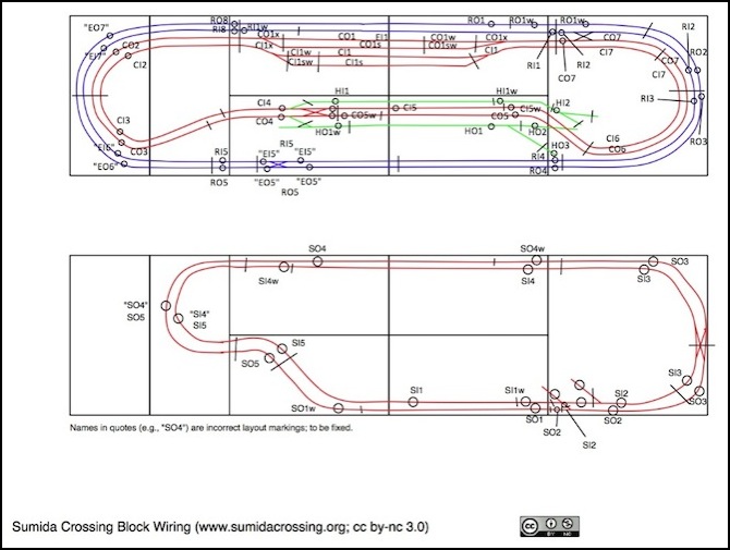
Block Isolation and Feeder Identification (version 3)
Note that blocks suffixed “s” or “w” are electrically distinct blocks from other sharing the same number (e.g., CI1 is the inner commuter line track in the urban station, and CI1s is the adjacent siding, but each has its own occupancy detector. I’d originally planned to use some short blocks around grade crossings, and had other suffix letters related to that, but I realized that all I needed was to put the gap on the exit side of the crossing since I’m designing for unidirectional operation. That’s prototypical for Japanese railways, but I would need to be a bit more complex if I were modeling a bi-directional North American prototype.
Address Assignments
The following sections record the assignments I’m using on the layout.
Addresses below 100 are reserved. As noted above 1-45 can appear on unconfigured equipment so I’m avoiding use of those. I could use the higher ones in the future if I needed some addresses.
101 - 200 will be used for turnouts.
201 - 400 are available and may be used for the SE8C.
401 - 500 are reserved for occupancy detectors.
BDL168 Assignments
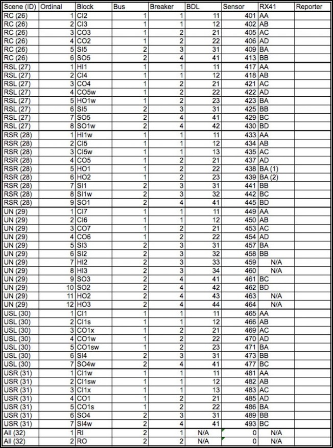
Assigning the blocks to power buses and breaker outputs based on their track, and to BDL detectors based on their breaker output, provides the assignments detailed in the table below (the “BDL” numbers below refer to quadrants on each BDL and outputs 1-4 within a quadrant). Each section with a darker outline and ordinals that restart from 1 indicates a distinct PM42/BDL168 combination, seven in all. This approach uses no more than 8 outputs per BDL, meaning every block can be transponding, and it avoids any need to run detector-to-feeder wires between tables. The only downside is that it inflates the cost of the PM42/BDL168/RX4 system to $1,780. Fortunately due to my slow progress, the cost is going to be spread over about three years, since I started acquiring these things a couple of years ago and I’ll probably defer the last couple for a few more months.
Note: This table treats the entire Rapid Inner (RI) and Rapid Outer (RO) lines as a single block each since these connect to only one circuit breaker output, using the second PM42 assigned to the unsceniced curve.
DS64 Assignments
The following address assignments have been made for the DS64 systems.
Urban Scene
DS64 #1:
121/122 = Commuter Inner Siding
123/124 = Commuter Outer Siding
Riverside Scene
DS64 #2:
101 = Commuter Outer Branch & Safety switch
102 = Commuter Inner Branch
109 = Commuter, Crossover
119 = Rapid, Crossover
DS64 #3:
103 = Commuter Outer, Subway/Helix link
104 = Commuter Inner, Subway/Helix link
two switches available for storage track use
DS64#4:
131 = Subway Outer, Commuter link
132 = Subway Inner, Commuter link
129 = Rapid/Commuter crossover
139 = Subway crossover
References
There are a number of helpful websites with more information about LocoNet:
Allan Gartner’s Wiring for DCC Booster Network Wiring page describes some potential issues with LocoNet.
Digitrax LocoNet page.
Digitrax Manuals page.
JMRI Digitrax DCC page.
JMRI article on Using Digitrax Devices on a Non Digitrax DCC Controlled Layout (PDF), by Elmer McKay.
Railway Bob’s LocoNet Pages.
RR-CirKits page on Powering Throttles on Loconet.
