


Track Voltage, Motor Voltage, and DCC
Originally posted 21 August 2010.
Update 2: 8/22; #1: fixed a couple of typos and, #2: corrected some mistaken info (thanks, Don).
I don’t normally alter musings after they’re published, but some of my info here was sufficiently misleading that I felt it necessary to correct it. I’ve replaced the square wave diagrams with ones showing the correct voltages, and made several textual changes related to RMS voltage and peak or peak-to-peak voltage. I’ve also corrected similar text on the referenced DCC Power Systems page.
As I’m finishing up the wiring for the two upper-level loops (one of which will be DCC-only, the other will be the switchable DC/DCC line), I’m also getting my DCC electronics set up and ready for use. There are several aspects to this, and I’ll cover others in future musings. But today I’m going to write about track and motor voltage. I could have just used the command station as it came, and it probably would have worked fine. But I like understanding exactly what’s going on under the hood, and so I ran a number of tests and spent some time researching what the track voltage should be, and why, and what that meant for the motor on a train. And if I ever add a booster, it will be important for it and the command station to be set to output the same voltage (this avoids problems when a train bridges between two power districts), so I may as well pick a voltage now.
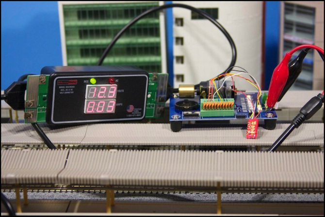
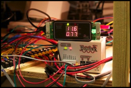
The above photo illustrates what I consider two essential tools for a DCC layout (assuming you don’t just buy off-the-shelf DCC equipped locomotives). On the left is an RRampMeter, which measures DCC voltage and current, and can be used to confirm that track and feeders are wired properly and without excessive loss. On the right is a decoder tester (in this case, an ESU 51900, which is particularly nice as it includes a motor), which can be used to verify correct operation of a decoder before it is wired to a loco, or if something isn’t working properly to test the decoder away from any locomotive circuitry. You don’t need these specific ones; you can even make your own DCC meter, and there are other decoder testers available too. But I like these.
Voltage, more specifically DC voltage at the motor, is what makes model trains go. In a basic system, a power pack puts variable DC onto the rails, and the motor picks this up. Positive voltage (right rail higher than left rail) makes the train go forward, negative voltage (right rail lower than left) makes it go backwards. Digital Command Control (DCC) is just a method for mixing a constant voltage source and commands on the track, so that a decoder on the train can supply variable DC to the motor depending on the commands given.
DCC Voltage - What is it?
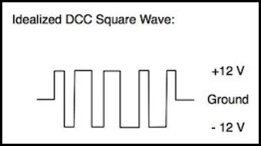
Before going further, I should say a few words about what is meant by “Volts” when dealing with DCC. Unlike simple Direct Current (DC), the DCC signal is not a constant current in one direction (the definition of DC), but rather an alternating current in the form of a square wave that’s positive roughly half the time, and negative the rest of the time. Since this is Alternating Current (AC), it can’t be directly read by a DC meter. But since normal AC is a sine wave, and DCC is (roughly) a square wave, it can’t be read accurately by even “true RMS” AC meters (or at least it doesn’t seem that way; see my DCC Power Systems page for a longer discussion of my testing of this). There are two measures of an AC voltage. One is the RMS voltage, which is a measure of the average power contained in the signal (i.e., you can treat DCC RMS voltage like DC voltage when calculating power with Watts = Volts x Amps). The other is the peak-to-peak (highest positive to lowest negative total voltage difference). A square wave that went from +8 to -8 would have 16 volts DC peak-to-peak, and 8 volts RMS. With a true square wave, RMS voltage is exactly equal to the voltage difference between the midpoint of the wave and one extreme (this is called “peak” voltage, not to be confused with “peak to peak”). DCC isn’t a pure square wave, so there will be some difference between peak voltage and RMS voltage in practice.
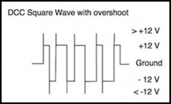
Peak measurements can be misleading, as it’s hard to make a square wave really square, and usually there’s some overshoot at the leading edge of each wave. Under load, or at the end of a long bus wire, the waveform becomes more distorted, and while the overshoot and other distortions typically don’t contain much power, they do change the highest DC voltage seen by a meter. So RMS voltage (which should equal peak voltage in a pure square wave) become less and less related to the peak voltage measurement as distortion increases. Peak is most useful measured at the command station with no load on it (i.e., no trains running), as this will have the minimum distortion.
So when we talk about DCC “voltage”, we’re usually talking about an RMS voltage (often called “DCC RMS volts” or just “volts”), which is roughly equal to the peak voltage, rather than one of the other measures.
Note that if you run as 12 volt peak square wave through a rectifier (which is essentially what a decoder does), you’ll get a constant 12 volt signal (minus the loss in the rectifier, which is typically around one volt) as the power supply. This is further varied by the decoder, to supply the motor with a variable voltage from 0 to the output of the rectifier (possibly minus additional loss in the decoder circuitry that varies the output). Thus the maximum motor voltage will be less than the peak (i.e., RMS) voltage.
Standard Track Voltage, Or Not
But what should that voltage be? The NMRA long ago standardized maximum voltage for trains (i.e., what their motor should receive at full throttle) as a range of 12-16 volts DC, and when DCC was introduced they noted that the DCC voltage on the rails should not exceed “the voltage specified in standard S-9 for the applicable scale” by more than 2 volts. Regrettably, S-9 doesn’t actually say anything about scales, or much about maximum voltages for that matter; only that the maximum must not be less than 12 volts “at the maximum anticipated load”. The maximum normal voltage (16 V DC) is defined in a Recommended Practice (RP-9, PDF), and the maximum output of a DCC power station is defined to be 22 volts in S-9.1 (PDF). S-9.1 further defines the minimum peak track voltage for DCC to be +/- 7 volts (i.e., RMS voltage may be as low as 7 volts) and the NMRA will rate as “conformant” (PDF) a decoder putting out as little as 7 volts DCC RMS.
This is presumably to support things like Z scale, but clearly in conflict with the requirement of S-9 to output no less than 12 volts (you can’t get 12 volts out from 7 in without some fancy footwork, and it’s unlikely that that is what was intended). This almost certainly reflects S-9 predating the popularity of smaller scales, and having a bias towards the HO and O-scale modelers, who were vastly in the majority in 1984 (and may still be). Perhaps the NMRA is planning an updated S-9 with multiple motor voltages by scale.
That’s a bunch of numbers, but what it boils down to is that motors should expect 12-16 Volts DC, and DCC command stations should output a waveform with a peak voltage of no less than 12 volts, with an RMS value no less than 12 Volts DCC RMS (except that less is clearly acceptable under some undefined circumstances).
There is, however, a fairly widespread convention that DCC voltage should be 12 volts for N-Scale, 14 volts (or 14.25 or 14.5) for HO, and 18 volts for O and G scales. Since this isn’t defined in the NMRA standards, it may come from Lenz (whose technology evolved into the standard DCC). Or it could simply be a reflection of a pre-existing industry convention for DC models that was never standardized. The NMRA actually alludes to this in a diagram in S-9.1, but the text makes it clear that this page is about voltage limits, and the “typical” voltages given in the diagram aren’t part of what’s being standardized.
You’ll note that if motor voltage is going to be less than DCC track voltage (which it is due to losses in the decoder), then a DCC track voltage of 12 volts technically violates NMRA standard S-9, because the maximum delivered to the motor can never be 12 volts, which is the lowest allowed maximum. The moral of this, if you needed one, is that standards only get you so far, then reality sets in.
Beyond that, there’s no reason a Japanese manufacturer is necessarily going to abide by a voluntary standard promulgated by a North American organization. And some Japanese N-scale trams are designed for lower voltages. However, Kato’s power packs do output 0-12 V DC, so they’re in line with other N-scale manufacturers and I think I’m safe in basing my plans on “typical” N-scale systems and standards.
Measuring and Adjusting the Command Station
My DCC Command Station is a Digitrax DCS100, which supports the three “typical” voltages (via a three-position toggle switch on the front panel). With it set to “N-scale”, track voltage was initially 11.4 volts DCC RMS. There’s an adjustment set-screw, and I could raise it as high as 12.3 volts DCC RMS (as seen on my RRampMeter in the photo up above), although I eventually settled on setting it to exactly 12.0 volts DCC RMS at the command station.
Digitrax suggests a method for measuring peak DC voltage in their manual, which is to use a DC meter to measure each rail relative to the ground line on the command station, and add the two numbers (this is effectively measuring the +12 and -12 values in the diagram above, except that the meter is only measuring half the wave, and averaging the peak voltage with zero, so the results would be around 6 volts, and adding the two halves will get you back to peak voltage, and eliminate any bias due to one peak being higher than the other).
Since the result after adding is peak voltage, it should be approximately RMS, although distortions in the waveform are likely to make peak slightly higher than RMS. I tried this method, as well as using a “true RMS” meter, for comparison. What I saw was that with no load (throttle at 0), the RRampMeter read 12.0 V DCC, my “true RMS” meter read 11.64 V AC RMS, and the peak reading was 6.19+6.12=12.31 V DC. Running the decoder up to full speed didn’t really put much load on (track voltage was unchanged at 12.0, my meter read 11.55 V AC RMS, and peak was 12.30 V DC), and resulted in a motor voltage of 11.1 V DC.
Voltage will drop with significant load (that’s true of most electrical systems, but I confirmed it here, see the above-noted DCC Power Systems page), and friction-fit Unijoiners aren’t the best conductor in the world, so with a command station output at 12 volts DCC RMS, actual DCC at the decoder could be as low as 10 volts. I’ll need to run some tests with real DCC trains (full-length, with lighting for the maximum load) and see how things behave. But I’m fairly confident that this is an acceptable voltage for my trains, since full speed is going to be much faster than commuter trains run in the real world. I expect I’ll end up programming the decoder speed tables with “maximum” values considerably less than 100%, even with a reduced track voltage figured in. As long as the decoders behave well under such circumstances, and I’m not anticipating any difficulty, this should be fine.
Track Wiring and Voltage
Beyond simply providing me with a few evenings’ amusement, this also gave me something to think about while I was checking my track with the RRampMeter to see how well the wiring was. What I discovered was that my bus wiring was good. Even with all the terminal strips and crimp-on connectors, my worst-case voltage under the tables was just 0.1 volts lower than the output of the command station. Topside was another matter.
I did my testing by equipping the RRampMeter with an artificial load, in the form of a 12 volt automobile tail light. This gave me a 0.8 Amp load, which is representative of two or three full-size trains; in short, probably a bit more than the worst case of a typical block. Loads cause the track voltage to drop, and the also cause voltage losses in poor connections to increase.
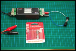
Meter with lamp, and connected to circuit (this was with track voltage of 12.3 V DCC).
And the track, alas wasn’t quite as good as the bus wiring feeding it. One of the things I’d previously done was measure resistance rail to rail across each Unijoiner connection with my multimeter (yes, that’s a lot of measurements), and discarded any Unijoiners with significantly higher than usual resistance, assuming they’d been bent out of shape due to repeated use and were making poor contact. Despite this, I saw significant voltage loss across even just a few sequential Unijoiners. With my artificial load, voltage at the command station dropped by 0.7 Volts, and I saw over one additional volt lost between feeder and the most distant part of some blocks, taking track voltage down to around 10 volts in places. I think that’s still acceptable, although it means maximum motor voltage will vary between 9 and a bit below 11 Volts DC, so I’ll admit to being a bit nervous. I’ll be paying close attention to this when I get around to running my first DCC trains and setting their speed tables.
But for now, I’ve done what I can and the track is as clean as it’s going to be without drastic actions like feeding every Unitrack segment (not practical) or soldering Unijoiners in place (not something I want to do on a layout designed to come apart for moves). Now I need to finish wiring up all the track feeders for the two upper loops, and doing the other necessary DCC work (stationary decoders for turnouts, circuit breakers, and debugging my UR92 wireless throttle system, which for some reason is working erratically). I’m working on that in parallel with the scenery and topography for the Riverside Station scene, so hopefully it will all come together in a few more weeks.
Other website updates:
- I created a photo album for Electronics photos, and populated it with a bunch of past and new photos of the wiring and other systems.
- I’ve also added photos to the Station, Construction and Diagrams (revised track plan) photo albums.
- I’ve rearranged my various pages about the design and construction of the layout’s electronics systems, rewriting a few of them that were badly out of date due to changes in my plans over the last seven or eight months. See the Electrical Systems page for links to those pages.
- I installed my first DS64 stationary decoder (see the “Phase 2i” Construction page) for throwing turnouts, and assigned DCC accessory addresses to all of the turnouts (which I’ll use as I program additional ones). That’s additionally described on the LocoNet page (one of the Electronics pages I mentioned), and I’ll have more to say about LocoNet in the future. The track plan was revised to show the turnout numbers.
- I added some more text and photos to the prototype Passenger Locomotives page.
- I made some changes to the format of the Home page, as well as other minor cleanup elsewhere.
