


More Electrical Work
Rather than turning my attention immediately to the Riverside Station scene, I decided to get the electrical systems ready for the eventual use of the two “ground level” loops, which will require DCC. And that meant I needed to finalize my plans. And although most of them had been worked out last year, and revised (in my head if nowhere else) over the winter, there was still a bit of planning needed before I was ready to start cutting wire. This had to encompass the DCC systems (both power and the LocoNet control bus) as well as the various power strips to supply them, and some additional power supplies for eventual LED lighting. I’d started thinking more intensely about this while I was working on the wiring recently, but needed to bring that to conclusion and write down the results.
I also spent some time running trains, since the first two tracks are capable of running DC trains.
So part of the last week was spent revising the design for my DCC and other wiring. The result is a fairly complete description of the revised plans on my Power Wiring Design and LocoNet pages (along with a couple of helpful diagrams). I’ve also been giving a good deal of thought to my signaling design, and the current state of that is described on my DCC Japanese Prototype Signals page. That’s still subject to change, as I haven’t built the prototypes yet (the ribbon cable needed to hook everything up is on back-order and I’m still working out some of the details of my signal design and will need to order more parts).
I’d originally planned to use my Zephyr as the DCC command station, but a little math showed that it was hopelessly inadequate for six tracks worth of trains. I’d actually figured this out several months ago, and bought the necessary power supply and command station along with the other DCC elements I’ve slowly been accumulating over the winter (I still need to buy a few more circuit breakers and occupancy detectors before I can wire everything up; those things are expensive).
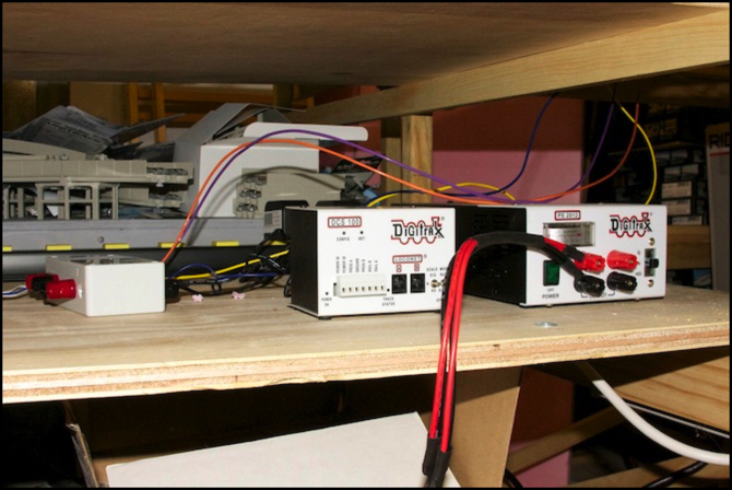
The photo above shows the PS2012 power supply (right), the DCS100 command station (center) and the fuse box for the two 1.5A lighting power supplies (left), all on the “electronics” shelf below the right end of the Riverside Station scene. The black bar with yellow rectangles is a switched power strip used to power the various “wall wart” power supplies (so I can turn them off when not in use, independently of things like the computer I may leave on in an “idle” state). In the background is one of the storage-track tables, with spare unitrack stacked on it.
The expected number of LocoNet devices has passed the number (20) at which Digitrax recommends subdividing the LocoNet control bus with repeaters (LNRP). I’ll have a couple of those, which would normally mount on the layout fascia, but I don’t plan to put them there, as it would interfere with the placement of the plexiglass. So instead I needed to build a “control panel” for the electronics shelf. This is basically just a sheet of hardboard with cut-outs for the LNRPs and a couple of other things (all train control will be via computer, so there are no switch controls or similar on this panel) that will attach to a plywood base with brackets. That was another thing I built this weekend, but the paint needs to dry (and preferably set for a couple of weeks to become fully cured and hard) before I install the electronics, so I don’t have a photo of that yet.
Although I don’t plan to actually build the signaling system for some time, I do need to figure out where the signals go, and how they’re going to be wired before I finish the scenery, as I need to make allowances for wire runs and signal mounting points.
The short description of my signaling plans is that I intend to scratch-build four-aspect signals and a couple of two aspect station-entry signals, plus a couple of position-light “repeater” signals where it would be hard for an engineer to see the signal they are approaching. These may end up slightly oversize, but I’m going to try to get as close to the prototype appearance as is possible. I could try converting Tomix DC four-light signals to DCC, but at nearly $40 each, that would get really expensive.
These will be driven by a Digitrax SE8C decoder, using a bunch of TSMK signal drivers. The actual control logic will reside in JMRI scripts on my computer, and will depend on both the BDL168 block-occupancy detectors and DS64 turnout controllers (which JMRI will also be monitoring). Actual implementation of any of this is well off, although I expect to do some prototyping in the next month or two (I’m waiting on parts right now).
I expect I’ll be doing some wiring over the next couple of weeks, and starting to hook up the DS64 and PM42/BDL168 modules, as well as turning my attention to the Riverside Station foam. But it’s probably going to be more than a month before the first DCC train runs. Which reminds me: I really need to finish installing lighting in all the cars of the one train I have converted to DCC, so I can have a good train to test with. I had that nearly done last fall, then had some trouble removing the body from one car and put it aside for later. Later never came.
