


Raspberry Pi Touchscreen
Until recently touchscreen (or touchpanel) displays were both small and expensive. That all changed in late 2015, when the Raspberry Pi Foundation introduced a touchscreen accessory for the Raspberry Pi. This is a large 800 x 480 display with 24-bit color capable of displaying 60 fps video, and it includes a high-quality touchpanel. The display has an active surface of about 3 1/4 x 6 inches (8.5 x 15.5 cm) and costs just US$60. Since the Pi can run JMRI and a touch on the panel acts like a mouse-click, this makes creating simple touch-based control panels using the Pi quite easy, and with a total cost around US$200, including the Pi and assuming some kind of control bus interface, rather inexpensive.
Note: there are lots of “touchpanel” accessories for the Pi, generally both smaller and more expensive. Make sure you get the Official Raspberry Pi 7” Touchscreen.
If you don’t want to use JMRI but are comfortable with programming, you could also use the Kivy library to write touch-panel applications in Python. I don’t have any experience with that myself, but I’ve seen it recommended.
As usual with the Pi, things are sold separately, so you’ll need the Pi itself. One of the B models is probably the best choice, so you will have USB ports for connecting to various things. You will also need a power supply and memory card. A full 2 Amp power supply is recommended (or two smaller supplies, see below). If you plan to connect to a control bus (such as LocoNet) you will need a USB adapter for that as well.
Note that with the touchpanel connected, the other display connectors are inoperative (although they can be used for video, such as a camera output). I create my Pi’s memory card on a Pi with a normal monitor and get VNC (remote console) working, before I put the card in the touchpanel Pi. That way I can work on the Pi from my computer with a large monitor using VNC, rather than trying to edit files on the small touchpanel screen.
I’ll cover the software aspects of control panels using the Pi elsewhere, as the same methods apply to both small touchpanels and large displays. This page will talk about the technical aspects of using the panel. One comment on software: the touchpanel support is built into Raspbian Jessie, so that’s recommended as the operating system if you want to keep things simple.
Note: my experience to date with this has been on the model 2B; I haven’t yet tried using JMRI and/or the touchscreen on a model 3.
Pi Selection
Which Pi you use is up to you, as long as you use one compatible with the touchpanel (i.e., not the original A or B or the Pi Zero, it must be a +, 2 or 3). While you could use a 3B, that’s probably more power than you need for a simple control panel, unless you’re going to be doing more. I’d use a 2B myself, although a hypothetical future 3A with WiFi may be a cheaper option (I’ll have to see when it comes out).
It may actually be possible to use the original Pi, but it would require soldering I2C lines (SCL & SDA) onto the Pi, as the ones on the GPIO pins are apparently for the wrong bus. And there’s apparently some kind of software support that was needed but not available at release. I’d just use the later Pi models, where I2C was included in the flat display cable so you don’t need to do anything.
Touchscreen Assembly
There are plenty of instructions online for assembling the panel, not that there’s really a whole lot of assembly required. In the U.S. the primary distributor is Element 14, and their website includes a link to the assembly instructions. I’ll just cover some basic considerations.
Note: there’s a film of protective plastic wrap over the front of the display. Leave that in place until you have the panel fully assembled and ready for use (or even until you have it mounted) to reduce the risk of scratching the front face, which is not hardened to prevent scratches.
As usual when handling electronics, try to work in a way that minimizes the risk of static electricity (called “ESD safe”) and handle circuit boards by their edges to avoid touching the individual components.
The instructions talk about connecting the actual display to its controller card (two flat cables) and screwing that to the inner set of mounting points on the display. In the ones currently being sold, this seems to have been done at the factory, so all you need to do is mount the Pi itself.
The Raspberry Pi needs to mount onto the control board. There are standoffs on the board, and the package contains the needed screws (really small phillips). Make sure you attach the Pi so that the end with the rectangular “display” connector is mounted at the same end as the matching connector (also marked “display”) on the control board.
Actually, it is possible to flip the Pi over, so that the cable runs between the Pi and the control board, or with it twisted, although that may produce extra stress on the display cable. This makes the whole assembly thinner, which is helpful if mounting in a very constrained space. However to do that, you’ll either need two power supplies or the USB splitter cable (as described below) or you’ll have to bend the two GPIO pins used for power and ground on the Pi so that they stick out to the side.
Although you don’t need a case (and it would be hard to attach one), it’s not a bad idea to protect the exposed electronics on the Pi. A small sheet of plastic with holes that match the screw positions and a notch for the display cable can be used, but I prefer a couple of hex standoffs with an Adafruit Pi Protector top panel (which has a cutout for the display cable, so you don’t have to make a notch where the cable goes.
Once the Pi is mounted, connect the flat cable in the box between the two multipin “display” connectors (either way works). This cable makes all of the display and touch-panel connections to the Pi. Be sure to connect to the “display” connector, as the Pi has a similar connector marked “camera”.
Note that the display connectors have a small plastic latch with tabs at each end that needs to be pulled out a very short distance (just over 1 mm) before the cable can be inserted. Pull gently with a fingernail on one end at a time to loosen, then insert the display cable and push the tabs back in (again, gently) while holding the cable in place. It’s possible to do this with two hands, but it helps if you have a friend hold the cable while you latch it.
Powering the Assembly
There are basically two ways to power this: power the Pi and the display separately, or power one and connect the two together. The latter method is simpler and what I use.
Both the display board and the Pi have the same micro USB connector used for +5V power. To power them individually, simply connect two separate power supplies. For the display, the Pi Foundation says that a 500 mA supply is sufficient (I haven’t measured it myself). For the Pi, it depends on the model. For the 2B, a 1,000 mA supply is the minimum, and you’ll probably want something closer to 1,200 mA, more if you have significant USB use.
A simpler method is to connect the panel and Pi together by running the included red and black jumpers from the pins on the display’s control board to the appropriate GPIO pins. You can find the instructions for this on the Element 14 website. Doing this requires a larger power supply, and the full 2 Amp version recommended for the Pi 2 (or the 2.5A for the Pi 3) is probably a good idea, although I expect that provides a good margin for additional peripherals.
To do this, you’ll need to connect the red and black cables that come in the box between the Pi’s GPIO header (+5V and Ground, GPIO pins 2 and 6 respectively) and the control board’s pins. Then you connect your power supply to either the control board or the Pi itself. It doesn’t appear to matter which, although most instructions imply that the control board is preferable. However I’ve run a panel off the Pi’s power for an extended period, with no apparent problems, and my reading of the electrical specs says that this should be okay.
If you want to use one power supply, but keep the GPIO pins clear for a cable or HAT, you can buy a split USB cable that breaks out one power supply to two USB micro connectors (Pimoroni makes one, but I haven’t found anyone in the U.S. reselling it). This is probably the best solution for a permanent mounting (micro USB connectors are much less likely to vibrate loose than a simple GPIO jumper).
Mounting
A panel like this can easily be mounted to the layout fascia, presuming you have a large enough one, with room behind it. You’ll need about 7.5 x 4 inches (18 x 11 cm) on the outside, with a cutout of 16.5 x 10 cm (6.5 x 4 inches) and about two inches (5 cm) of interior clearance, although it’s that deep only for a smaller portion.
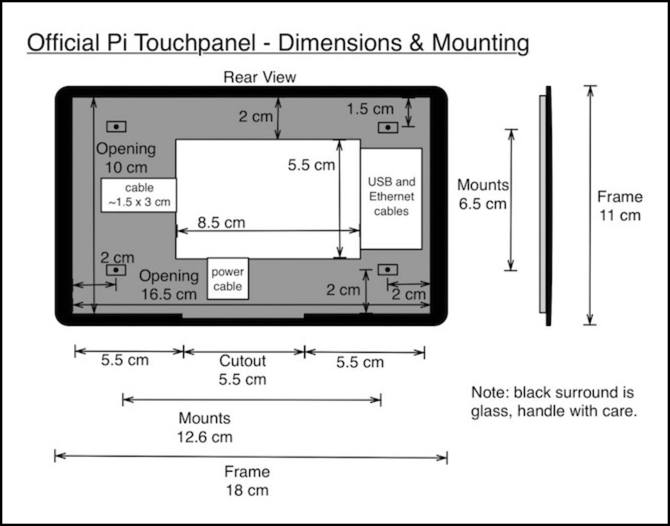
This diagram is placed in the Public Domain, feel free to reuse it as desired.
The panel has a thin black surround that is slightly larger than the gray steel case holding the panel. This is actually an extension of the glass front of the display (yes, that black bit is really glass!) so be careful not to put too much force on it, and don’t try drilling it for mounting holes.
There are four screw connectors on the back, threaded for metric M3.0 screws (not the same as the four inner connectors for the control board, which are reportedly metric M2.5). One way to mount this is to make a cutout just large enough for the metal case, push the panel in from the front until the black surround is flush with the fascia, and then attach two thin strips of metal to the screw connectors from the back, to clamp the panel in place. Be careful to clamp gently, the glass front should just be resting against the fascia, not pulled hard against it. Alternatively you could epoxy the panel to the fascia rather than using screws, but that would make it a bit harder to work on.
The cut in the layout fascia should be as level as possible along the bottom, although you can use tape to shim one side so that the display sits level if it isn’t quite right.
Note that if you use this approach, there is a ribbon cable on the bottom of the display, so you need to make a small cutout in the fascia to keep the cable from being pinched by the weight of the panel resting on it, or make the whole cutout slightly taller, and shim both sides to raise the display up slightly.
While it’s possible to mount a touchpanel upside-down and invert the display (putting the ribbon cable at the top), don’t do that. The display has a much better viewing angle from above when the ribbon cable is facing down. One exception: if you were mounting the panel above eye level (e.g., on a valence above the layout), mounting upside down and reversing the display in software would give you a better viewing angle from below.
The panel can lie flush for typical mounting heights and distances. If you need to work up close on a very low panel, you may want to angle the base out slightly (this will require a bit more work to attach). If doing that, you should support the black surround to avoid breaking it. Using one of the layers from the Pimoroni frame (also available in the U.S. from Adafruit) as a support would be a good idea. Note: the full Pimoroni frame mounts the display upside down (cable at the top), but that’s because the legs only fit one way and upside down works better for tabletop/shelf viewing of a slightly-angled standing display. If you just use one layer as a support, you can mount in any orientation.
