Block Wiring
To manage all of the wires involved in feeding power to the track, I need conventions. This page summarizes those and the block structure of the layout.
Bus Wiring
As described on the Wiring Standards and Power Wiring Design pages, I have a number of track buses. These are divided into a set that runs along the front of each table, and a set along the back. There are also some separate bus wires (e.g., for scenery lighting).
Note: this section is repeating material from the Wiring Standards page so it will all be in once place for reference.
Front set:
- DCC Bus #1 (Commuter Track), Red/Black 14 ga wire
- Accessory Power Bus #1 (signaling and Block Occupancy systems), Blue/Yellow 16ga wire
- DC/DCC Bus #3 (Express outer track), Orange/Purple, 14 ga wire
Rear Set:
- DCC Bus #2 (Subway track), Red/Black 14 ga wire
- Accessory Power Bus #2 (Switch power), Blue/Yellow 16 ga wire
- DC/DCC Bus #4 (Express inner track), Orange/Purpur 14 ga wire
PM42 supply: In the end, I split the PM42 systems off from the switch power, and gave them their own power bus. This is powered by a 1.5A, 15V, power supply (only about 875mA is required) and run separately on each table using 16ga wire (color code TBD).
Lighting Bus: brown/white 18ga wire
There is a separate lighting bus for each “scene” (three in all), wired independently back to their own supplies. These are limited to 1.5A of power each, which could power up to about 200 LEDs each if I wire things very efficiently. I may eventually need to power each table separately if I get enough lights installed. For more about lighting, see the DC Power Supplies page.
Line and Block Labeling
For both wiring and control systems, it is useful to have a simple label that denotes a set of contiguous track, or the blocks within it. The following format is used:
Note: this has been updated, with the labeling of blocks now done across the whole loop, rather than within a scene. This will make it harder to re-arrange the scenes into an along-the-wall linear layout someday, but it makes much more sense now (otherwise I’d have four block 1’s, and very few block 2’s for each loop). Also, the “scene identifier” and main/siding qualifier have been removed. A siding will now have a unique sequential block number.
LTnc
where:
L = Line identifier:
“S” for subway,
“C” for commuter (inner loop),
“R” for rapid (outer loop), (I used both “E” for “Express” and “R” for “Rapid” on the tables)
“H” for helix (including topside tracks between the Commuter, Subway and Helix),
“Y” for storage
T = “I” for inner, “O” for outer (nearest table edge)
n = sequential occupancy detection block number (1 to x)
c = qualifier:
“w” for warning; warning blocks have the same block number as an adjoining block.
“s” for siding; siding blocks have the same block number as the adjacent main track.
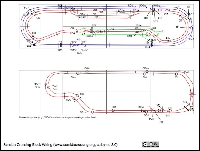
Note: a siding block adjacent to Main block “n” will have the same block number but be suffixed “s”. Also, a warning section on a siding if suffixed by “sw”. Thus, the commuter inner line in the Urban station has blocks CI1, CI1w, CI1s and CI1sw.
Thus:
CI1 = Block one of the inner (counter-clockwise) track of the commuter line.
and
RO2w = Warning section adjacent to block two of the outer (clockwise) track of the Rapid line.
Track Blocks
The track is separated into a number of electrically isolated blocks. Each block has one or more feeders, and both rails are gapped at both ends of a block, ensuring that any block boundary can be a power district boundary if I decide to rewire those later (it also makes problem isolation easier as they same problem won’t affect two blocks in any manner).
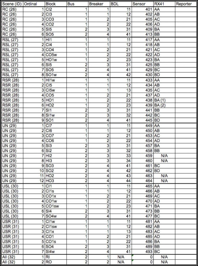
Block Detection Wiring
On each table, one or more power protection and occupancy detection panels provides a set of four DCC circuit breakers, and up to eight detection and transponding sections (technically there are sixteen detection sections on a BDL168, but at present I’m only using half of them, as the transponding is limited to eight).