


LocoNet: A DCC Control Bus
DCC is really about getting power and control information to the track. But there’s another side to it: how do the commands from the throttle (the controls) get to the DCC system, and how do different parts of the DCC system communicate with each other? The first part isn’t covered by the NMRA’s DCC standards, so each manufacturer does the throttle-to-command-station link in their own proprietary manner. The second part is partially standardized, as the NMRA has Recommended Practice RP-9.1.2 Power Station Interface to describe how a command station sends commands to booster stations, but they don’t say anything about how devices like stationary decoders or occupancy detectors report their status, although there’s a draft of a standard for an “NMRAnet” control bus being developed which will probably fill this gap, someday.
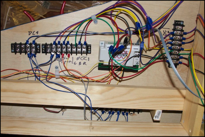
DCC accessories can be controlled by commands taken from the track, so there isn’t a need for a separate control connection. Unless, that is, you want the devices to be able to report back to the command station (or some other system, like a computer). For example, to report what position they are in, or when the track is occupied. In which case you need a “control bus” that permits both sending and receiving information. The photo at the top of this page shows a DS64 accessory decoder used for throwing track switches (turnouts), with the flat gray LocoNet cable that allows it to report the position of a turnout to a control system, such as a computer running the JMRI software.
Digitrax created a fairly sophisticated control bus, based on a low-speed (16.6 Kbps) packet-based twisted-pair network. This allows device-to-device communications between multiple devices, not just to/from a command station. And that yields a lot of benefits. Both Lenz and NCE also have feedback capabilities, however Lenz uses a polled system rather than a network (I’m not clear how NCE’s works). In fact, LocoNet is sufficiently flexible that some people use it for computer control of turnouts or signals when using non-Digitrax command stations to run trains (PDF).
The NMRAnet is a packet-based peer-to-peer network, similar to LocoNet but operating at 128 Khz and based on an existing standard industrial control network, which should eventually make implementation relatively simple for manufacturers. But it’s not here yet, so for now LocoNet is probably the best control bus out there. I think so anyway, and it’s a big reason I stayed with Digitrax when I decided to upgrade from my original Zephyr command station to a larger system.
LocoNet is pretty simple to use. The wiring uses 6-conductor telephone cables, which can easily be assembled with a modular jack connector crimping tool you can get at most any hardware store (finding the six-conductor cable and the connectors may be a trifle harder, as most telephone wire uses four conductors). With these, you just plug things together in a chain, and it only gets complicated if you have a lot of equipment, or a very large layout.
And what’s actually happening on the wire is pretty simple too. Although LocoNet has six conductors, two of these are used for the command-station to booster signal (which may be RP-9.1.2 compatible, although Digitrax doesn’t claim that; it’s certainly a very similar signal), and which is also used as a low-current power supply to some devices since it’s basically a low-power DCC signal. Two others are ground lines. And the LocoNet signal itself is just a simple serial signal relative to ground, which for arcane reasons is duplicated on two wires, but it’s not an out-of-phase duplicate to reduce noise; the two wires are simply connected to each other, with the same signal on both. All an accessory needs to participate in LocoNet is a simple serial chip, and a bit of software.
Because LocoNet is basically a low-speed serial signal, it’s possible to connect the wires in a lot of different ways; as long as it doesn’t circle back on itself, if will generally work over distances of hundreds of feet, and with a fairly high resistance to electrical noise from other electronics.
That’s not to say it’s trivial: Digitrax did a few things to make it a bit less robust than it might have been, including building some devices that only use the LocoNet signal from one of the two wires, and not actually putting a copy of the signal on the second wire at the command station, but assuming some other device would connect the two wires together. Even their own UP5 panel doesn’t do that, although the LNRP and UR92 do (and others may, but those are the ones I’ve tested). It pays to read up a bit (and these two pages also) if you’re designing a large LocoNet system.
And because LocoNet handles both the Command Station to Booster signal and the device-to-device communications for signaling, occupancy detection, handheld throttles and similar things, there’s a bit of risk that problems with one device can interfere with proper operation of the layout. With larger layouts they recommend segmenting the layout using an LNRP (or multiple); basically if you have more than 20 devices, it’s time to split things up. It’s also a good idea to test all the wiring with an LT1 as you make it.
So I’ve designed my LocoNet to be three connected networks, plus a “protected” section between the command station, any future boosters, and the LNRPs feeding those networks. Because the LNRP is a repeater, any device can still not only communicate with other devices, but monitor the communications between any two other devices. And that’s handy for computer automation, where the computer can see a handheld throttle tell an accessory decoder to change state, and cause a status display to update. That’s a capability I eventually plan to take advantage of when I create a “dispatchers panel” display of my track, switches and signals. Having three sections means my throttles, turnouts, and occupancy/signaling systems will all be isolated from each other, and an electrical problem in one will not affect the others, nor can any of them affect the command station’s communication with (future) boosters. For more about LocoNet in general and my LocoNet design, see my LocoNet page.
My actual throttles are wireless DT402D hand-held models, which communicate with the LocoNet via the UR92 panel. I have one UP5 panel connected to a PS14 power supply that’s always on, and the throttles plug into this when not in use, to keep their batteries from running down.
I’m pretty happy with the design. If it all works as planned I’ll be able to run trains wirelessly, to control turnouts from the throttle and/or a computer, to detect block occupancy, and to have a computer control signals based on that occupancy detection. And all of that is thanks to LocoNet.
The LocoNet itself is mostly built; my first DS64 for turnout control (photo at top of page) is installed and working. The wireless throttle works, sort of, although it keeps resetting and I need to figure out why. I’ve yet to install the circuit breakers or occupancy detectors, or the signaling system, or most of the DS64s. And the computer is still connected to the Zephyr on my workbench, where I’m programming DCC decoders in trains (well, that’s the theory, actually finding time to do that has been hard). So there’s more yet to do before the design is fully realized. But I’m well on my way.
Other website updates:
- Updated the Roster, Commuter EMU, Other Passenger Trains, Freight Trains and Reservations pages to reflect my new EF65, cold-weather DE10, and some additional info about Kato’s Suburban E231 models, as well as some more stuff on order.
- Updated my Adding DCC and Lights page to reflect some additional info on power consumption (more remains to be done on this, and I’ll probably eventually post a separate musing on the topic); surprisingly, my first DCC train uses a whole lot less power than most descriptions on the net had led me to believe (news flash: not everything written online is accurate! Who knew?)
- Did some additional cleanup on the Power Wiring Design and DCC Power Systems pages.
- Added a page describing my experiences so far in making retaining walls using casting plaster. This is still “in progress” as I write; I’m waiting for the second casting attempt to set and to see if it comes out intact. The first failed, but I think I know what I did wrong.
