


What’s a Watt?
Basic Electrical Concepts for Model Railroading (DC edition)
This page is an introduction to the basic terminology and concepts needed to understand electricity as it applies to model railroading. It also includes an example of how to wire up LEDs (used for building lighting or similar) to a power supply. It’s not a primer for doing anything complex; there are undoubtedly better people than I to explain such things. This page is just here for complete novices.
Model railroads use Direct Current, or DC. This is electricity that always flows in one direction, as opposed to Alternating Current, or AC, which reverses direction 120 times a second. That’s not quite a true statement, as model railroads use AC from the wall to power the DC systems, and they also make use of Digital Command Control (DCC), which is like AC except that it reverses direction thousands of times a second.
But DC is the important stuff. It’s what makes the motor in the train run, and DCC is just a fancy (and optional) way to get DC to the motor. In N-scale, the standard DC voltage is 12 volts. HO uses 16 volts, and many power-packs for HO/N scale will put out 16 volts or more, but some models are sensitive and a 12-volt N-scale power supply is recommended.
Note: DCC systems will sometimes have a switch to set voltage, but not always. Digitrax’s popular Zephyr puts out 14 volts, but as Kato re-sells this for their n-scale trains, apparently 14 is “close enough” to 12.
Electrical Circuits
In any discussion of electricity, you need to think in terms of an electrical circuit: a closed loop including the source of power (a battery, or wall outlet, or whatever) and the “load” (device being powered). Electricity can only flow in a circuit, and when it does that flow is called the “current” in the circuit. However, it always picks the path of least resistance to make that circuit, so if you give it more than one option, it’s usually going to use just one. That’s another of those not-quite-true statements, as if the two circuits are close in resistance, the electricity will flow through both, but not evenly. If they’re far apart (like in a “short circuit” where one path has essentially zero resistance) one of them will get nearly all of it.
Most people writing about electricity like to use a plumbing analogy, where voltage equates to water pressure, resistance to pipe diameter (it’s harder to move water through small pipes, so small pipes are like high resistance wires), and current to, well, current (rate of water flow). I’m not sure how helpful this is, unless you’re a plumber to begin with, but perhaps it helps to visualize things. So, if it helps to think of electricity this way, by all means do so; it’s a good analogy.
There are three important aspects to electricity: the intensity of the source (measured in Volts), the rate of flow through the circuit (Amperes of current) and the difficulty in pushing current through the circuit (Ohms of resistance). There’s a fourth measure, related to the others, of how much energy is being used, called “power” (measured in Watts).
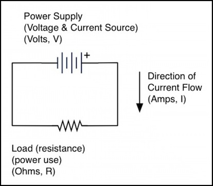
A very basic circuit
Volts, Amps, Ohms, and Watts
A volt is a unit of “pressure”, for lack of a better word, abbreviated as “V”. The higher the resistance in a circuit, the more volts it takes to move the same amount of power through it. And the corollary is that for a given resistance, increasing the voltage increases the current flowing in the circuit. But voltage isn’t the whole story, as a power supply has a limit on how much current it can provide (its “power”). As resistance goes down, a power supply can provide more current, but it can’t provide more power than it has, and that will ultimately limit the current.
Twelve volts DC isn’t all that much; it could give you a mild shock, but that’s about it at the power levels used for model railroading. However, DCC systems use more power, and 12 volts of DCC could do some damage with sufficient power behind it. I’ll come to that in a bit. But basic model railroading uses DC on the track, and at power levels that are safe even for small children to play with.
When electricity flows through a DC circuit, it creates a “current” that moves from “positive” to “negative”. Actually that’s another not-quite-true statement. Electricity has two polarities, and the actual direction of current between them is really irrelevant. It helps to think of it as moving in a specific direction, so long ago one was picked. They had a 50/50 chance of picking the correct one (this was long before anyone figured out what an electron was), and they got it wrong. We can thank Benjamin Franklin (yes, that Benjamin Franklin) for that. But the idea stuck, so even though the actual electrons that make up electricity move from negative to positive, the current is still said to flow from positive to negative. Confusing to novices, but it really doesn’t matter.
Current is measured in units called Amperes, or Amps (A) for short. For many model railroad situations, a more useful measurement is milliAmperes (milliamps or mA), or thousandths of an Amp. So a model locomotive may require 500 milliamps to run, and an LED light may need just 30 to 50 milliamps to light it. Current is abbreviated as “I” rather than “C”, because André-Marie Ampère was French and he used the word “intensité”, or so I’ve read.
Resistance is what gets in the way of current flowing. Conductors, like copper and other metals, have relatively low resistance. Wood, plastic, glass and other insulators have very high resistance. Some conductors are better than others. The nickel-silver used for rail is a pretty poor conductor actually, which is one reason it’s a good idea to connect the power supply to the tracks every six feet or so; it will certainly work if you don’t, but about 20 feet of track is enough to visibly slow a locomotive due to the loss of power in the rails. Resistance is measured in Ohms (or sometimes milliOhms) and usually designated with an “R” in formulas, although the greek letter Omega (“Ω”) is used to label numeric values (i.e., “R=50Ω” can be read as “Resistance is 50 Ohms”).
Typical 24 gauge copper wire such as Kato uses in their Unitrack feeders has a resistance of 19 mΩ (nineteen milliOhms) per foot, while code 80 nickel-silver track has a resistance of 76 mΩ per foot when powering one train, and this rises to over 300 mΩ per foot when powering several (resistance rises with increased current). And larger wire has much less: the 14 gauge wire recommended for a power bus on a DCC model railroad has a resistance of just 3 mΩ per foot in typical use.
Note: it’s easy to get confused when working with volts and milliamps and it’s generally best to convert everything to the non-”milli” version (i.e., divide by 1,000 and think of “20 milliamps” as being “0.020 amps” instead). If, when you’re done, the number is less than 1, multiply by 1,000 to get “milli”-whatevers.
Finally, “power” is a measure of how much electricity is needed to do something. Power is measured in Watts, which you’re probably familiar with from the “100 watt light bulb” in a lamp. That’s a bulb that uses 100 watts to produce a little light and a lot of heat (incandescent bulbs are not very efficient light sources; most of the power is wasted as heat).
You get watts with DC by simply multiplying voltage (in volts) times current (in amps), so a watt is sometimes written as VA. AC is a bit more complicated, but it’s roughly the same. Watts are designated “W”, or “mW” for milliwatts (a milliwatt is volts times milliamps, or millivolts times amps but that’s not commonly used). Another way to put this is that P = VI (power in Watts equals Volts times current in Amps). This is one form of what’s known as Joule’s Law.
Those are the basics: volts, amps, ohms and watts. But there’s one more relationship to know: remember when I said that voltage is what is needed to move power through resistance? That’s summed up in “Ohm’s Law”: Voltage divided by Resistance equals Current (V/R=I). This is more useful when expressed as V=IR or R=V/I, although all three mean the same thing.
Resistors
Anything that uses power has resistance, but sometimes you need to deliberately add more resistance to a circuit. That’s where the resistor comes in. This is a device that converts power to heat (i.e., throws it away), in a very precise manner.
Resistors come in standard values, and have accuracy ratings. A 100 ohm 5% resistor could be between 95 and 105 ohms, but would be marked as “100 ohms, 5%” (there’s a color code for the markings). Typical resistors are 5% or 10% types, although you can get more precise ones. However, the cost quickly goes up for higher precision, and for most model railroad applications precision isn’t really needed.
Standard sizes for 10% resistors are:
10, 12, 15, 18, 22, 27, 33, 39, 47, 56, 68, 82, 100, 120, 150, 180, 220, 270, 330, 390, 470, 560, 680, 820, and so on (e.g., 1000, 1200...).
Standard sizes for 5% resistors are all of the above, plus:
11, 13, 16, 20, 24, 30, 36, 43, 51, 62, 75, 91, 110, 130, 160, 200, 240, 300, 360, 430, 510, 620, 750, 910,...
Resistors also have a power rating (e.g., 1/4 Watt). You calculate the rating needed based on the voltage dropped by the resistor times the current used by the connected load (such as a train motor or LED). And it’s a good idea to have a large safety margin, so if you’re using more than 60-75% (e.g., more than 150 mW to 188mw on a 1/4 Watt resistor), you should step up to the next higher rating.
Resistance in series is additive. If you need a 30 ohm resistor but don’t have one, you could connect a 10 ohm and a 20 ohm resistor end to end, and the result is the same as if you had a 30 ohm resistor.
DC Track Examples
So, to make a concrete example, a train that uses 500 milliamps of current at 12 volts is using 12V x 0.5A, or 6 Watts of power. Not much, compared to a a light bulb.
For another concrete example, if you have a current of 500 mA (one train’s worth) flowing through ten feet of track with resistance of 76 mΩ (milliohms) per foot, then there will be a voltage drop of V=IR = 0.5A x 10 x 2 x 0.076Ω = 0.76 volts due to power lost in the rails, which isn’t very much (the “x 2” is because you have to count each of the two rails). That lost power goes to heat the rails, but the amount is so slight you’d never notice it.
DCC Example
But if it were a DCC layout with enough current for six trains (6 x 0.5A = 3 Amps), and a resistance of 300 mΩ per foot (3Ω total) , then you’d have a voltage drop of V=IR = 3A x 10 x 2 x 0.3Ω = 18 volts, and since you started with just 12 volts, that means it isn’t going to work at all. This is why DCC layouts don’t use a single track feeder, but instead use heavy-gauge bus wires connected to the track in multiple places.
Note: I used 300 mΩ per foot in this example because resistance actually goes up for larger currents.
A DCC Cautionary Note
Because DCC layouts can power multiple trains, they need power supplies that put out several Amps of power (typically between 2 and 8), rather than the small supplies used in typical DC power packs (which put out 1 -2 Amps at most, and often under one Amp). This means that the current can punch through fairly heavy resistance (and in doing so produce a lot of heat), and what that means is that two pieces of metal that are close together but not quite touching (like the wheel of a derailed train and the rail) can actually have current jump through the air between them (air has quite a bit of resistance, but if the gap is small, you’ll get an electrical arc across it). And that produces enough heat to melt metal, and weld the wheel to the rail, or start a fire on any flammable scenery nearby.
DCC power supplies have circuit breakers to protect against this kind of problem, but there can be situations where those aren’t quite good enough. And that’s why I said DCC wasn’t quite as safe as DC. It’s safe enough for an adult or teen who knows to pull the plug if there’s a problem, but it’s not something I’d let a child use unsupervised, particularly not with the larger (5A or more) power supplies.
Power Supplies
There are three important characteristics in a power supply: AC or DC output, voltage, and maximum current (or power). If you want to power a few simple accessories or lightbulbs, a typical model train powerpack will usually have an accessory output that provides a limited amount of AC current. If you are looking to power LED lighting or other more sophisticated circuitry, you’ll probably want a DC power supply, rated for 5 to 16 volts (12 volt supplies are fairly common, and useful), and probably under one amp of current. Larger supplies are needed for some things, but handling larger currents can be more dangerous and one large supply is often more expensive than several small ones.
Note: since the voltage is fixed, you can get power from maximum current ratings, and maximum current from power ratings. Remember P=VI (which is the same as I=P/V).
The simplest power supply is a transformer that can be plugged into a wall outlet. These come in both AC and DC versions (the DC models include a rectifier to convert the AC output of the transformer to DC). The cheapest produce “unregulated” power, meaning that the voltage is only approximate, and may vary. A more sophisticated, and expensive, supply will be regulated to produce a constant voltage regardless of variations in the input power or load.
Digitrax makes the PS14, a 14-volt, DC power supply with a maximum current of 300 milliAmps. This has a “stabilized” output (what that means isn’t clear, except that it probably has some form of regulation). This lists for about US$13. One advantage of the PS14 is that it has a built-in circuit breaker in case of overload, so you don’t need to add a fuse.
However, Sparkfun sells a 12-volt, 600 mA regulated supply for US$5.95 that’s a nice size for lighting or small accessories. And if you buy 10 or more, there’s a discount. It doesn’t include a circuit breaker, so you should add a fuse (see below). If you look around you can probably find others around 1 Amp for reasonable prices.
Such power supplies typically come in the form of a block that plugs into the wall outlet (this contains the transformer and regulator), with a cord having a 2.1mm jack as the output, but this can be cut off and the supply connected to layout wiring (preferably via a screw-down “terminal strip” connector, so the supply can be removed for testing or replacement). Or you can buy a matching 2.1mm socket, and connect that to the layout, allowing for quick removal of the power supply.
Another option is to re-use the power supply from an old desktop computer, as these provide both 5V and 12V DC outputs of several Amps. The only disadvantage of these is that they put out far more power than you’re going to need (often tens of amps) and are internally fused accordingly. With the lightweight wire you’re likely to use on the layout, this could pose a fire hazard, and using a smaller external fuse is probably a good idea. Pick one sized to your actual needs (1 or 2 amps, most likely).
When connecting any power supply to the layout, it is a good idea to include a fuse. This will protect the power supply against any short-circuits in the layout wiring, and conversely protect the layout wiring against an overload caused by a short-circuit, which could otherwise start a fire or damage the wiring. A simple way to do this is to use an inline fuse holder of the kind used in automobile electronics (which also run on 12 V DC). Simply connect one end of a fuse-holder (Radio Shack 270-1281 for US$3 or similar) to the jack (or other connection on the positive output of the power supply), and the other to the layout wiring (perhaps via a screw terminal). The other side of the jack connects directly to the layout. It is usually preferable to connect the fuse to the positive side of the power supply (typically the center pin on the plug or jack) although that’s just a convention in this case. Then insert the fuse appropriate to the power supply rating (i.e., equal or less than the rating) and to your needs (at least 20% larger than what you need, but not a huge amount larger, and in any case less than or equal to the maximum output of the power supply).
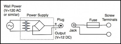
Adding an inline fuse holder to a wall-wart power supply
LED Example
Here’s another example: suppose you wanted to use the Digitrax PS14 DC power supply to power some LEDs used for lighting buildings and other scenery. The PS14 puts out up to 300 mA of current at 14 volts DC (so it is limited to 14 * 0.3 = 4.2 Watts of power). A typical “super bright” white LED is rated for 120 mW of power dissipation, and 30 mA of current at a “forward voltage” of 3.6 volts (you’ll note that 0.03A x 3.6V = 0.108 W, not 0.120 W, so the ratings are obviously a bit approximate). So, just off the cuff, you might assume that you could power ten of these LEDs off that supply (300 mA / 30 mA = 10). It’s not quite that simple.
First, the PS14 puts out 14 volts, not 3.6. Simply hooking up the LED to it would overload the LED, causing a “pop” and letting some smoke out, and that would be the end of the LED. You need to drop the voltage to 3.6 volts. One way to do this is to use a resistor. Recall Ohm’s Law: R=V/I. You want to take away 10.4 volts (14-3.6) when the current through the LED is 30 mA, so R = 10.4 / 0.03 = 346.6 Ohms.
Resistors come in standard sizes, so you probably can’t find a 347 Ohm resistor. Also, most resistors are accurate to +/- 10% (some are 5%, some 2%), so you need to pick a larger resistor (to ensure your voltage is lower than desired, not higher). The next standard value above 382 (347 + 10%) is 390 ohms, so lets assume you can get one of those (your actual choices might depend on what you had at hand or in the local Radio Shack’s inventory). Since it’s a 10% resistor, that means it’s really between 351 Ohms (390 * 0.9) and 429 Ohms (390 * 1.1), so it will actually drop the voltage by 10.53 to 12.87 volts, leaving the LED with 3.47 to 1.13 volts.
Both voltages are below 3.6 volts (the “forward voltage” or Vf rating of the LED) so that’s safe (it won’t harm the LED). At the lower voltage, the LED might be rather dim, although this tends to be self-correcting due to the way LEDs and resistors work (at lower voltage, the LED draws less current, so the resistor drops less voltage; the end result is that not as much reduction occurs as the math might suggest). Still, testing the LED and resistor combination to see if it provides adequate light is a good idea. That combination of LED and resistor by the way is using 420mW of power (30mA x 14V): 108mW in the LED and the rest in the resistor. We’ll come back to that.
Note: a LED is a “Light Emitting Diode”. A diode is a semiconductor that will only pass current in one direction, almost always from “anode” (positive side) to “cathode” (negative side). If you hook up a LED backwards it won’t light. Since LEDs normally have a maximum allowed reverse voltage (Vr) that is larger than their forward voltage it may not be harmed, and this effect is used in some types of circuit. Still, it’s a good idea to make sure your LED is in the right orientation, and has the right size resistor, before applying power. Buy spare LEDs too; you’ll undoubtedly fry a few of them (I do).
In any case, for lighting to work, you need to get the direction right. The cathode is typically marked in some way: with ordinary LEDs having leads, one is usually shorter than the other, and this is the cathode. Sometimes other marks are used (e.g., a “tab” or “band”), or one side of the LED case will have a flat spot, but these are all normally on the cathode. Unfortunately, surface-mount LEDs (a.k.a., SMDs) don’t always adhere to this convention, and these are the really small LEDs most likely to be needed in n-scale applications. LEDs have specification sheets (usually PDF files downloadable from online sales sites, or the manufacturer; you can google for the LED part number and the word “datasheet” if all else fails), and it’s a good idea to read these for any LED, but almost essential when working with SMDs.
Or, you can just test it. If you have a multimeter with a “diode” mode, that can be used, otherwise hook up a wire with the appropriate size resistor to a power supply (either the layout one, or on a workbench) and just touch the two contacts briefly to see which direction causes it to light. There’s some risk of blowing the LED when you do this if you’re using a supply greater than 5 volts if you touch it longer than “briefly”; testing with a small battery would be preferable.
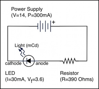
A Simple LED circuit
Now that’s one LED. You might think you can string a bunch in a row, but each needs 3.6 volts, and that’s additive so ten would need 36 volts, and you only have 14 volts to work with. Obviously, one long string isn’t the right approach.
Back to that power supply: it puts out 300 mA at 12 volts, the LED needs 30 mA, so you could hook up ten of them (each with their own resistor) in parallel, meaning that each LED+resistor chain has one end connected to the positive output of the supply, and one end to the negative. This does indeed use 300mA, and power ten LEDs, but it’s throwing away most of that power in resistors.
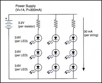
The answer is to string LEDs together in series, so each string makes the most possible use of the power supply. This works best if all the LEDs in a string have the same current (milliAmp) rating, but each string can be different. It is also important that each string has a resistor, as this helps the LEDs draw the proper amount of current. Thus the total voltage requirements of each string of LEDs (before adding a resistor) must be less than the power supply voltage and a resistor must be added to use the rest.
With this example (Vf=3.6V), you can use at most three in a row, as that needs 10.8 volts, leaving just 3.2, which is less than the amount required for a fourth LED. You need a resistor to get rid of the remaining 3.2 volts (107 ohms by the formula above, +5% is 112, and the next standard size is 120 ohms). If you want to maximize the light output, it is best to get as close to Vf as you can get, by using a more accurate (5% or even 2%) resistor, and picking one as close as possible to the needed value (but stay on the high side to avoid over-driving the LED, which could damage it). On the other hand, lowering the voltage slightly (using a larger resistor) will lower the current draw, and while this reduces the output, it also extends the life of the LED. You only need to reduce the voltage a small amount (perhaps 5%), and the approach described above essentially does this since the resistor is always slightly larger than needed, but you could probably use a 150 Ohm resistor and still get a fairly bright LED, using much less power and extending the LEDs life.
Now, each string of LEDs still uses 30 mA (the current doesn’t change just because there are three LEDs in a row; more power is used, but that’s because each LED has 3.6 volts of its own, and uses the same amount as a single LED (3.6 x 30 mA = 108 mW), there’s just less power wasted in the resistor (3.2V x 30 mA = 96 mW to be precise). And that means you could connect 10 strings (300 mA) to the power supply, with thirty LEDs total, instead of ten.
Another way to look at this is that when the manufacturer said “300 mA”, they really meant “300 mA x 14 Volts = 4.2 Watts”. If each LED draws 108 mW, then a string draws 420 mw (3 LEDs at 108 mW each plus the resistor at 96 mW), and again you can power 4.2 / 0.42 = 10 strings. Note that the number of strings (10) is the same in both examples, because it is the string that consumes 420mW in both cases.
A general rule-of-thumb is to load an electrical circuit (i.e., a fuse or circuit breaker) no more than 80% of its rated load. In other words, not loading the PS14 beyond 240mA, or in this example eight of the ten strings. And thus, instead of the ten LEDs you might think could be powered, you can actually power twenty-four and still have a safety margin. Digitrax actually says that you can operate three of their DCC units that need 100 mA off of the PS14, so its 300 mA rating may already be the 80% number (or they may be overestimating the requirements of their DCC equipment). You may well be okay with ten strings on the PS14. But when working with other supplies, I’d attach a fuse equivalent to the rated value or less, and load them to 80% of the value of the fuse.
Note: an earlier version of this page had the capacity of the PS14 computed incorrectly.
A more sophisticated method for powering LED lighting
For more information about LEDs for model railroad use, see my LED Lighting page.
