


Modeling Prototype Signaling I
Today's post follows my earlier series on prototype signaling (Part I: Development and Part II: Blocks), but it's about how to capture a specific prototype environment on a model railroad. For example purposes, I'm going to look at a real-world location I plan to model, Ochanomizu station and the crossovers just west of it. This is a fairly complex case, as it involves a junction of two double-track lines. On the other hand, it's a relatively simple station without multiple platforms per track, which simplifies things a bit.
The question at hand is: how would I replicate somewhat realistic prototype signals for this location? It's an important question, as I'll eventually need to do it. And determining the right answer is a good way to clarify my understanding of the topic, so I can create similar solutions for other locations on the layout. I may or may not actually do it this way when the time comes, but working through this example now helps clarify my thinking.
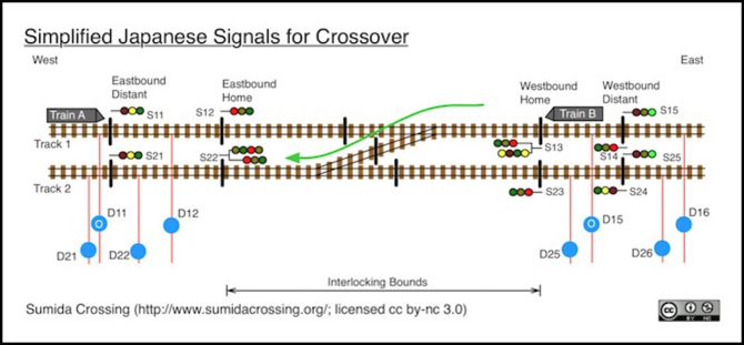
But I’ll get into the detail of that in another post. For now I’m going to focus on the signals and related systems around a simple crossover (above) so that I can introduce the various pieces that make up the whole, and explain how they fit together.
I started by studying everything I could find about the real signals at this location, which I wrote up as part of my post about this line. Mostly that involved looking at photographs, although before that I'd studied the MLIT document (PDF) that defines how Japanese railroads are supposed to use signals, as well as checking Wikipedia and other sources. I cover all of that in my prototype Signals pages.
Signals are directly related to blocks, so let's start with what a "block" is and how that relates to a model railroad.
Blocks
In prototype railroading a "block" is a section of track that can normally be occupied by only one train. Exceptions are sometimes made, e.g., for one train rescuing another that has broken down, or two trains following each other at a restricted speed (or, in older days, under timetable rules). Some sections of track aren't blocks: for example yards are generally treated differently, with multiple trains active at low speeds under visual rules. Interlockings (places where trains may cross paths with other trains) are also usually considered to be distinct from blocks, although subject to similar rules. Stations are often interlockings, but even when they lack switches they may be treated like one to allow more control over train movements. However, stations may also exist within a single much larger block, depending on the railroad and the size of the station.
Electrical Sections
In model railroading there are several kinds of "blocks". In addition to blocks used for signaling, we can talk about sections of tracks used for control purposes. For example, in multi-cab DC layouts panel switches select different power packs for a length of track. Here each length of switched track is a separate electrical block, which isn't necessarily equivalent to a signaling block.
With DC, you can never have more than one train per electrical block, so those are likely to be equal to or shorter than signaling blocks. With DCC, blocks for signaling are somewhat independent of train control electronics. But there are still interdependencies.
One reason for electrical blocks on DCC is so that the track is isolated because it is connected to some device needing isolation, such as a current-based occupancy detector (I'll just call these "detectors" from here on). Another reason would be because it is fed from a different booster.
To avoid confusion with signaling blocks, I'll refer to those as "electrical sections", meaning lengths of track that are isolated from contiguous tracks via gapped rails (or insulated rail joiners) and which may be fed power differently from their neighbors.
Digitrax uses several specific terms in its documentation: a "power district" includes all electrical sections supplied from one booster, a "power sub-district" is a subset of that with an independent circuit breaker (or auto-reverser, which is really a form of circuit breaker), and finally they use the term "detection section" for an electrical section that has a detector. I’m going to focus in on the electrical sections, both with and without detectors, but you should understand that there is more to the track power system than just this part.
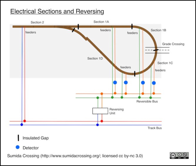
It's possible to build larger sections from multiple smaller sections. For example, a reversing loop containing a grade crossing would be all fed from one auto-reverser with gaps at the switch so that the whole loop could be reversed in phase (i.e., the whole loop is a “power sub-district”), but it would be further subdivided with a gap at the crossing, so you could detect when a train was on one side or the other. On a long enough loop, you might even have multiple detectors on each side so that the crossing only activated when the train was close. In the diagram below, there are four detection sections within the loop, plus one electrical section (section 2) without a detector outside of it.
It’s worth noting that electrical sections and track feeder wiring are not the same thing. Each electrical section needs at least one set of feeders but it can have more, as long as they split after the wire goes through the detector. In section 2 only a single feeder is shown, but in reality there will be several feeders attached to rails on either side of the switch frog (and a reversible one to the frog itself, assuming that is electrified). All of those are part of section 2.
Signal Blocks
Now consider the prototype block on a model railroad with signals. We need to know where trains are for the signals to work, so a block might be one electrical section with one detector. But if you want to be more prototypical and support approach-lit signals or overruns (important for some kinds of signaling), you need to subdivide the block into multiple electrical sections each with a detector. This is also useful if you would want to implement an Automatic Train Control (ATC) signaling feature, where the operator's throttle is overridden by the signaling system if it approaches a "Stop" signal at too high a rate.
I may eventually want that, as it is an important operational detail for a modern passenger-centric railroad (which is what I model). So I'm going to briefly go into the details related to it. However, actually doing that would be fairly complicated today, so I expect I’ll omit it from the initial version I build.
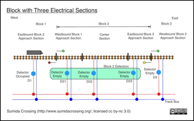
In the diagram below, block 2 has 3 detectors, any one of which being occupied marks the block as occupied. The two end detectors in block 2 (and those of adjacent blocks) also serve as approach sections.
The train shown is an eastbound at the end of block 1, occupying detector D1. As it has not yet entered block 2, the signal ahead of it shows "clear" (green) because the three detectors of block 2 are empty. Meanwhile the signal in the other direction shows "stop" (red) because one or more detectors in block 1 are occupied (i.e, D1). The signal at the far end of block 2 for a westbound move shows "caution" (yellow) since the train is one block out (block 1 is occupied, block 2 is clear).
Detector D1 can also be used for approach-lit signals, if you want to model those. In this example, the eastbound signal for block 2 would be lit (green, as shown) because a train was in its approach section. But the other three signals would be dark, because no trains are in their approach sections. I don't presently have any plans to model that kind of signal.
Finally, if a westbound from block 3 were to pass the yellow signal and eventually enter the section detected by D21, an automatic train control (ATC) feature could apply a timed reduction of throttle to slow it to a stop. Depending on the speed and length of D21's section it might overrun into the adjacent block, a risk in real-world systems also. This is why signaling systems sometimes use a short section of the adjacent block as an "overrun". In this case, D1 could be treated at part of block 2, but only for westbound trains (and similarly, D3 would be part of block 2 for eastbounds).
This is actually a fairly useful part of signaling to model, but it makes the system more complex (and not all prototype railroads use overruns). I believe Japanese signaling uses this concept, but the MLIT standards document doesn't explicitly reference it (it does talk about operational issues related to the risk of overruns).
A simpler Automatic Train Stop (ATS) feature would not apply a speed reduction until the front of the train passed the red signal and entered D1's section, at which point a harsher emergency stop braking reduction would be applied.
Implementing either in a model railroad would require that throttle commands be processed by a device aware of the signals, before being passed to the command station. This would be possible with a control bus that did not implicitly tie throttles to the command station. Such a system could probably be implemented in the future using LCC (by pairing throttles with that intermediate device instead of the command station), or perhaps hacked together today using separate bus systems for throttles and the command station with a computer between them, but it isn't a capability of any off-the-shelf control system I'm aware of.
Both of these control systems (ATC and ATS) are in use on the lines I model, and are described in general terms on my Prototype Signaling page (see the Signal Enforcement subsection). Today all Japanese Railroads that have signals apparently use ATS, but only Shinkansen and a few commuter lines (maybe only the Keihin Tohoku) use ATC. I don't yet know if I wish to model them. Approach sections add a lot of complexity to signaling, not to mention more detectors. I think I may omit them initially, but design to allow their later addition.
Signals, Blocks and Interlockings
With the basics established, I'm going to simplify some more for the actual layout design. More detectors might be useful, for automation or ATC/ATS replication, but they're also extra cost and complexity. So I'll start by limiting myself to one detector per signal block. There may be multiple feeders going through that detector (or rather one feeder that branches after going through the detector) but a train anywhere in the signal block will be detected by that one detector. Actually, I won't get it to be quite that simple at first, but with some refinement we'll get there.
I'll use a simple single crossover as an example. Things get a little more complex with a double crossover, but it's really just doing this twice, so a single crossover as example helps reduce the clutter on the diagram. Also, for the feeds I'm drawing a single wire with detector. Other wires, both returns and feeds without detectors, will exist, but their location doesn't matter to the signaling so I've omitted them to simplify the diagram.
One thing to keep in mind: home signals for an interlocking will always be red unless they are manually “cleared” by a human, at which point they take on aspects that depends on the state of devices (switches and detectors) within their block and on the aspect of the signal leading to the next block. A cleared signal will revert to non-cleared once a train passes unless a persistent “current of traffic has been established. And turnouts within the interlocking can’t be thrown if a signal crossing them is cleared (that’s the “interlock” part; you can’t make changes that would endanger a moving train).
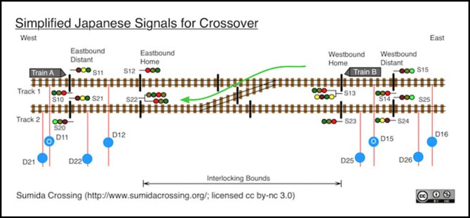
Here we have two tracks (numbered 1 & 2), subdivided into blocks for signaling. On the left is the end of a block with Train A in this first block of track 1. Detector D11 shows "occupied" because of Train A. This is followed by another block (between Distant and Home signals S11 and S12 on track 1, and between S21 and S22 on track 2). Then there is the interlocking itself, between the home signals. To the right, between the distant and home signals on this side is a third block, and finally to the right of that the start of a fourth.
The home signals (S12, S13, S22 and S23) will always be red unless cleared. The other signals are simple block signals, and depend only on detectors and the state of the next signal to determine their aspect.
Notice that signals S13 and S23 are the last westbound signals until you get to S10 and S20. This is because the interlocking is not itself a block, but rather a space between blocks that's treated as the beginning of the adjacent block in that direction. The eastbound and westbound blocks thus have bounds that overlap when the interlocking is considered.
A block is “occupied” if any one of the detectors within it are occupied (or if more than one is, of course). But the detectors associated with a home signal can vary, because the home signal controls access to different routes (and thus different blocks) depending on the position of switches within the interlocking.
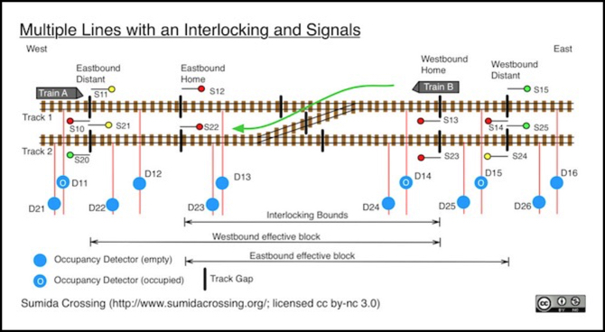
For example, Train B has just crossed into the section of the interlocking sensed by detector D14, with the rear of the train still in the block to the east, sensed by detector D15. It occupies two blocks, the rear of the train is in the block between signals S14 and S13 (detector D15), while the front occupies D14. But the “block” extends through and past the interlocking. If the turnout is not thrown, it extends to signal S10 on track 1. But if the turnout is thrown for the diverging route, then it extends from 13 (on track 1) to S20 (on track 2).
In this example the turnout is thrown for the diverging route. Thus signal S13 will remain red as long as any of detectors D14, D23 or D22 are occupied. And once those are clear, it will use the aspect of signal S20 to determine if it should show a “caution” (yellow) or “clear” (green) aspect, assuming the signal remains in a “cleared” state. If there’s no current of traffic, then the signal loses it’s cleared state as soon as D14 becomes occupied, and once the blocks signals are empty it will remain red because it is no longer cleared.
However, once the rear of the train clears detector D14 it will be safe to throw the turnout back to the through route since it is no longer possible for a train to enter the switch, even though the train remains in the block presently associated with signal S13.
Assume it is thrown back to the through route. When that happens, S13 will now apply to the block from S13 on track 1 to S11 on track 1. And if S13 is cleared after the switch is thrown it would become yellow since the signal's aspect is now governed by detectors D14, D13 and D12, which are clear, and the aspect of signal S10, which is “Stop” (red) because of Train A.
More usefully, with none of D13, D14 or D15 occupied, signal S12 can be cleared by the dispatcher to allow Train A to proceed on track 1, even as the tail end of Train B is still within the interlocking bounds on track 2. Since detectors D13, D14 and D15 are now empty, and S15 is green, when cleared S12 will also become green. And since S11 depends on D12 (empty) and the aspect of S12, it too will turn green, allowing train A to proceed at full speed.
Had train A arrived slightly earlier and passed S11 at yellow, it would have had to slow as it approached S12, until it saw S12 turn green when cleared.
Now this sounds rather complicated, with the signal having to be aware of the route involved. And in some prototype systems it is that complicated. Japanese signals are, mostly, simpler than that, a reflection of the "simpler things fail less often" philosophy that seems to govern their design. Let's look at the equivalent of this for Japanese signaling, with some additional simplification for modeling purposes.
Signal Aspects - A Simplified Japanese Version
First, I'm going to remove the detectors from inside the interlocking. In a prototype system, tracks inside the interlocking would normally be equipped with detectors, but since my interlocking is short and my trains will all be long commuter trains, no single train will ever fit inside the interlocking bounds. If this was a freight railroad with light engine moves, or if it was a small branch railroad with single-car or two-car DMUs then that wouldn't be safe, because a train inside the interlocking would "disappear" from the signaling system briefly. But for my purposes (long trains, short interlockings) some part of the train will always extend into an adjacent block, so it is safe.
Secondly, Japanese signals often use multiple heads on a mast, where each head is route specific. That's not the only option, but I can use it to my advantage for simplifying signals, and as it turns out, most of the signals on the section I am talking about modeling do indeed use this form.
Note: while Japanese signaling does sometimes refer to the signal before a Home signal as a “Distant” signal, there is a very specific definition for these signals, and they use a rectangular surround rather than the usual oval (see my Signal Types page). I’m using “distant” generically here, and treating them as ordinary block signals. That’s both a valid type of signaling, and it appears to be the form in use on the signals near Ochanomizu.
So, here we have train A approaching S11. As before this signal is yellow and S12 is red, because S12 is seeing the turnout thrown against it (and because it hasn't been cleared by the dispatcher, but even if it had the turnout position would force it to be red).
However, S13 now has two heads. We'll presume it's been cleared by the dispatcher due to the approaching train B. The right head remains red because it applies to the through route, and with the turnout set for a diverging move that route is inaccessible (i.e., the signal has to be aware of the state of the turnout). A three-lamp head is used here, because this signal only needs to show the usual three colors.
The left head applies to the diverging route. Because this crossing is limited to Restricted Speed (25 kph, about 15 mph) the signal can only show red ("Stop") or yellow-over-yellow ("Restricted Speed"). It can't show yellow ("Caution") because that allows a higher speed than Restricted Speed. Since there is no train occupying detector D22 the block is clear, so it doesn't need to show red, thus it can show Restricted Speed. However to show that, it needs a four lamp head (type 4A, to be specific).
Further, note that signal S22 is red for both routes. This is probably because it hasn't been cleared, but even if the dispatcher had cleared it, the fact that train B is occupying detector D15 would force the diverging route head to be red anyway.
Note: rather than sensing the aspect of the next signal, a single can simply look at those things (i.e., detectors) that would affect that signal’s aspect. This can get complicated at an interlocking, so it’s usually simpler to look at the aspect of a signal than to re-create all of the decisions that could affect that aspect. Real-world signals work the same way.
The logic for a two-head interlocking home signal is really simple. Here's an example in pseudocode for these two heads:
S13 Right Head:if not cleared then redelse if turnout = diverging then redelse if D12 = occupied then redelse if S10 = red then yellowelse greenS13 Left Head:if not cleared then redelse if turnout = through then redelse D22 = occupied then redelse yellow-over-yellowThe logic for a distant signal like S14 is even simpler, because it just keys off the next signal and one detector:
S14:If D15 = occupied then redelse if S13(right head) = green then greenelse yellowThis could easily be implemented with simple circuity, or very simple code in a program like JMRI.
One comment: on the prototype, I haven't been able to fully identity the signals used with the crossovers west of Ochanomizu station. There are a number of double masts with 4-lamp signals on both, but I think this is due to them also being on approach to station tracks (yellow-over-yellow is needed when a train is going to stop at a platform already containing another train). I also can't tell if they are type 4A or 4B (4B would be needed for a high-speed crossover, but I'm fairly sure these aren't long enough for that). The three-lamp head is used on block signals away from crossovers, and at least one is used on the through route of a two-head signal (this appears to be a distant signal rather than a home signal, but it may be a home signal further away from the crossover than usual due to a curve). So I think the above design, while simplified, is actually fairly close to my prototype.
Summary
That's it for this week. Next I need to talk about signals at station platforms. That’s probably complicated enough to warrant its own post before I move on to the complete system, but maybe I can combine the two.