


The Kato Grade Crossing
While I still plan to build my own grade crossing eventually, Kato’s update of their automatic grade crossing (model 20-652) to be compatible with DCC gave me an excuse to put that off some more (see Kato’s Japanese page for some pictures and a video of it in operation). Or at least, that was the plan. What I forgot in my enthusiasm is that I’d put my layout’s one grade crossing on a curve, so Kato’s straight crossing can’t be used. I can move it closer to Riverside’s commuter station, and I think I will. But I may end up using it somewhere else (perhaps on the “subway” tracks where they run at ground level under the Urban Station). I need to think on this some more, but I’ll outline my current plan after describing the crossing itself.
Note: I’ve added a Grade Crossing Photo Album to the Scenery albums, with larger versions of the photos seen here.
This is an active grade crossing, with LED lights, gates and an alarm bell, and not the same as the re-railer track (20-021) Kato sells in the U.S. as a “road crossing” (that one is made to look like a simple plank crossing for a rural road).
About the Crossing
As mentioned this isn’t Kato’s first grade crossing. The old one (part 20-650) used an electrical sensor, which didn’t work with DCC. The new one uses some kind of optical sensor and can work with either DC or DCC on the tracks. Kato clearly notes on the new box that the two aren’t compatible.
And while this crossing models a Japanese crossing, with black and yellow gates rather than red and white, and while the stop line on the street is for left-hand drive cars, the box is marked for Kato USA and is bilingual, so it’s a safe bet they’re planning a North American version too. With the old crossing, the red/white version received a different part number (20-650-1). Since the box is already marked for the new number (20-652) and “Kato USA”, it’s not clear if they’d do it again, or just use the same part number for two different versions, which is what they do for their Japanese (left side) and North American (right side) signals.
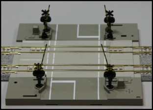
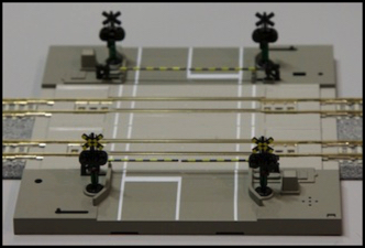
When not powered, gates can be positioned up or down via two levers (left front and right rear)
The Grade Crossing is really several parts. There are two side assemblies with the gates and lights. A “wall wart” DC power pack connects to one of these to power the crossing. One or more 124mm (4 7/8”) track segments goes between them, and track sensor wires connect to those. There’s also a set of 62mm sensor tracks (one for each side) that you install a couple of feet away from the crossing. Each expansion unit, more formally the Double Track Attachment Set (20-653) includes a 124mm crossing segment and two sensors with cabling. You can also get extension cables (20-654) to allow the sensors to be placed further from the crossing. Finally, if your road is at table-top level, there are a couple of angled roadway segments you clip to the crossing (which aren’t needed if you embed the crossing in the scenery or adjacent to a road plate (but more on that in a bit).
Kato says that you can connect up to five additional expansion tracks, to make a six-track grade crossing. Which may seem excessive by U.S. standards, but such crossings are fairly common in urban areas of Japan (some quite a bit larger exist, the largest was 11 tracks before it closed in 2009, although that was pedestrian-only). I’d love to have a four-track crossing, but I’m not going to re-do my track plan and layout scenery to create a place where all four above-ground tracks are parallel and can have a crossing. I’ll content myself with a two-track crossing at the entrance to the Riverside commuter station.
I bought the basic set, one expansion track (to make it a double-track crossing) and four sensor extension cables. I wasn’t sure I’d need those, but even at US$9 each, I’d rather have them and not use them than realize while installing things that I wanted them, only to find them sold out (as they are presently). All of this wasn’t cheap: the crossing itself goes for about US$210, and the expansion track for US$76. I paid a bit less since it was a preorder, but it’s serious cash for what is, after all, a rather toylike assembly. But then, I’ve never made any pretense of being a fine-scale modeler. And I think having a crossing with working gates and sound is worth the expense.
Operation
In operation, the gates lower, the alarm bell sounds, and the lights on the crossbucks flash in a typical alternating pattern. The internal mechanism sounds like one of Kato’s switch solenoids; there’s a distinctive “snap” when the crossing activates, and again when it stops. The gate arms are dampened, so after the snap they lower or raise at a “normal” speed. However one side of mine doesn’t want to go all the way up. It will if I hold the lever all the way over, so maybe it just needs to break in a bit.
The operation is all controlled by sensors. The crossing will work even if the track isn’t powered. There are sensors on the crossing itself, as well as on the sensor tracks. Each sensor consists of a central photocell and two IR LEDs (actually, they may not be “IR” as they emit a faint red glow in total darkness). It would appear that they function by bouncing light off the bottom of a rail car (I was also able to trip them by placing my hand or another object above them). They don’t seem easily confused by shapes moving between the room lights and the photocells at a distance from the track, and they operate the crossing even in total darkness (I couldn’t see my hand, but rolling a car over the sensor activated the crossing). All in all, there’s a feel of “good design” to the electrical and mechanical functions.
Each sensor connects to the crossing using a three-wire sensor cable. This cable is 47.75” (1.21m) long, and you can buy extensions, which consist of a second identical cable and a tiny circuit board with two back-to-back connectors to allow connecting the cables end-to-end. I’m not sure why you’d want eight feet of track between the sensor and the crossing, but you could do that if you wanted to.
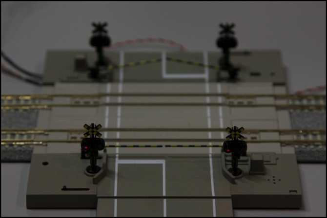
Crossing showing sensors (dark spot flanked by two yellowish dots)
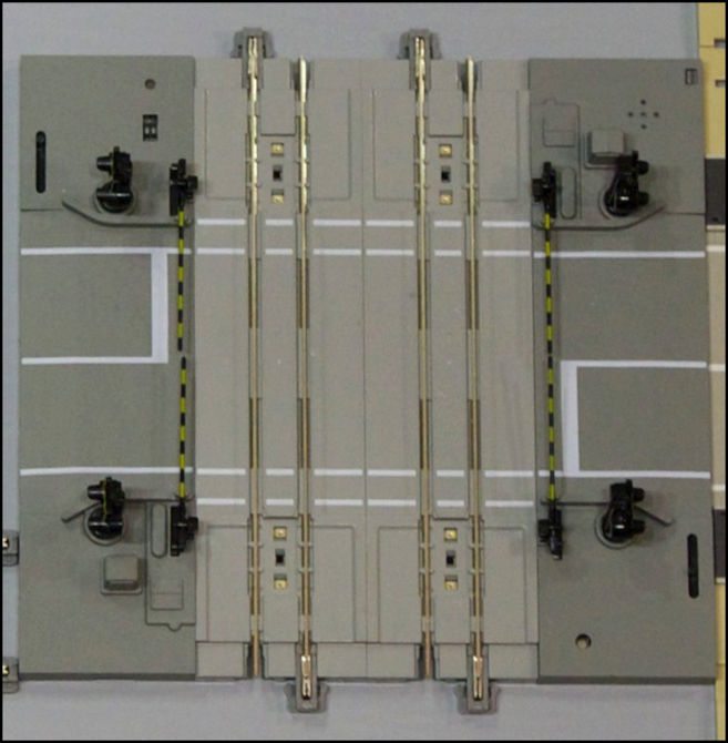
Each sensor has an adjustment potentiometer (pot), so there are two on each expansion track, since there is a sensor at each end, as seen below (the whiteish circles in the small square cut-outs, placed between the four large sensor-wire plugs. I’m not sure what it adjusts (sensitivity maybe?), but I didn’t need to adjust mine.
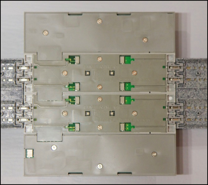
Underside showing wire connectors and adjustment pots
There seem to be a number of different ways to wire up the sensors. I followed the first diagram in the instructions (on page 2, numbered “1”) and the crossing worked just fine. Some of the other options have to do with more complex track arrangements, but I’m not really sure how.
The function is pretty straightforward, but with one surprise. When a car passes over the outer sensor track (in either direction) the gates come down and the bell starts to sound. But if the car passes back over the sensor after a pause without going through the crossing, the bell stops and the gates rise. I hadn’t expected that, and it’s a nice touch in case you need to make switching moves near a crossing.
In the normal course of use, a train passes over the outer sensor activating the crossing, then over the two sensors on the crossing. When the last car leaves the crossing, the gates immediately come up and the bell stops, without waiting for the train to cross the outer sensor. When the train crosses the outer sensor after leaving the crossing sensor, it doesn’t activate the crossing.
It’s also aware of the multiple tracks, so if one train leaves the crossing after another (on a separate track) has passed an outer sensor on the way to the crossing, the gates stay down and the bell rings, until the second train clears the crossing. It all works exactly as you’d want. And it seems to work reliably, in limited testing. I did manage to confuse it once when waving my hand over the sensors, and had to push the reset button on the crossing with the tip of a pen to get the bell to turn off. But aside from that one glitch, it worked well.
Three Kinds of Roads
There is one problem with the grade crossing: it’s not compatible with either of Kato’s DioTown or Unitram road plates. The base thickness is 7mm, the same as the Unitram plates, but the crossing roadway is actually beveled down to a 6mm height at the edge of the base. And, the width between the outer white lines of the roadway is 43mm, where the Unitram roadway uses 46mm for each of the two two-lane sides. Also, the track spacing is Kato’s usual double-track spacing, not the closer track spacing of the Unitram tracks, so you can’t even connect the rail part of it (unless you use one of the adapters that brings Unitram tracks out to the standard spacing). Finally, all three use a different color for the road surface.
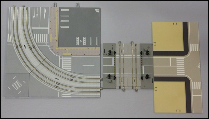
They just don’t match
You might expect that if the height doesn’t match the Unitram plate, that means that it would match Kato’s other road plate system, since that is structured for two-lane roads instead of four-lane highways. It doesn’t; DioTown uses a 4mm roadway height, and 47mm between the outer lines.
I can understand the height somewhat. DioTown (which came long before Unitram) was too low for embedded track, so Unitram road plates had to be at a different height. And a two-lane crossing isn’t going to work with a four-lane highway. But if they hadn’t beveled the edge, the crossing would at least have potential to work with an add-on two-lane road plate (assuming they’ll someday add one). And you’d think Kato could have picked one width (and color) for a road and stuck with it even if their hand was forced on height. But that issue aside, it’s a very nice crossing.
Using It
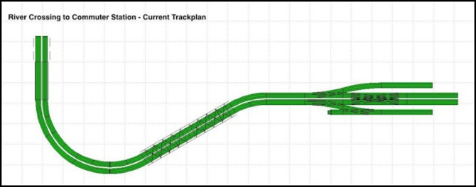
So now comes the problem of how to use it. Here’s the track plan as it presently stands, with the tracks crossing a bridge at the far left, curving to the bridges across the large river, then curving back to a short straight into the station. The placement of bridges and the switches to the branch line are inflexible unless I want to do major scenery rework.
Now I need sensors to the left, and there’s really only one place they can go, all the way at the end, just above the two bridges over the road leading to the Village area. That’s okay, as it gives a long lead warning on an entering train, and doesn’t prevent the grade crossing from detecting a departing train the moment it clears the crossing. It does mean I can’t have two trains along that stretch, but I was already planning my signaling system around that assumption so it doesn’t alter anything.
On the right, either I need sensors between the crossing and the switches, which would put them 64mm from the crossing itself, or I need four sensors, one on each branch line and one on each main line track. Trains in the station will need to keep clear of them to avoid prematurely triggering the crossing, which means they have to go as far left as possible. I’m left with only one possible arrangement without significant rework.
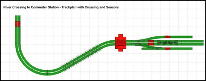
This shifts the position of the crossover right by 64mm, but that’s acceptable and better than putting the sensors right of the crossover, where they could get confused by crossing trains. This matches up well with Kato’s diagrams for branches inside the sensor reach. It does mean I’ll need two more sensors, and since they aren’t sold separately, I need to buy an expansion track (which comes with two sensors). Alternatively I could eliminate the distant sensor on the departing side, assuming I’d never have “wrong side” running. But that’s a weak assumption for the branch line switches, as trains may move in fairly complex patterns between the branch and the mainline via the crossover. So I’m better off with a full set of sensors.
There’s one weakness in this plan: while trains approaching the station from the left will have adequate time for the gates to come down even if they are expresses not stopping in the station, the same cannot be said of a train moving from right to left. This sensor position only works for a train moving at slow speed as it departs the station. That’s just a limitation I’ll have to live with.
I also need to deal with all the wires. The crossing will be a bit problematic, as it’s now above the styrene roof over the subway, but I think I can make that work. The right side is fairly easy, as there are already cable runs in the foam for power feeders (getting the new wires through those will be a project, but should be doable). The left end will need a little work, but nothing major. I’m also going to need two of my extension wires, as the left side is more than four feet from the crossing even without counting getting the wires under the table.
I need to let this kick around in my head for a bit to decide if the new road placement is acceptable, but I think it will be. And I need to order the expansion track before those go out of stock. But it feels like a plan.