


Power Wiring Design
This page describes the design of the layout track power systems and the various wires that connect them and the reasons that led to specific choices. For details of specific type and gauges of wires, see the Wiring Standards page. This page provides a more in-depth discussion of the reasons behind the standards, as well as detailing the specific construction of various elements.
Overview
All power wiring originates at the main power panel (coming from either DCC Command Station or Booster(s) or from a DC Power Pack). There is a reference and safety ground line (one wire for both purposes) also originating at the panel, which provides a reference level between DCC systems and a connection for currents created when a train bridges two separate DCC sources (e.g., when crossing between power districts). This ground also provides a drain for static charges that could otherwise build up in some components, and a safety ground in the event of a short circuit in the DCC power system.
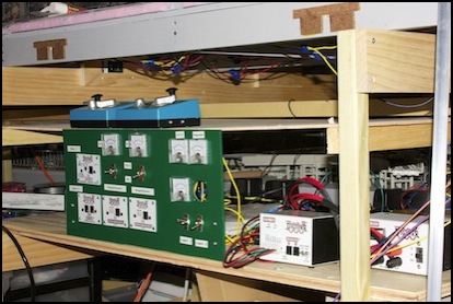
Electrical Shelf with Power Panel, Kato DC Controllers (top), and DCC Command Station and Power Supply (right)
From this panel, DCC and dual-use DC/DCC track power busses radiate out through the layout. These are linear (no loops: they do not connect except at the panel) and provide power to each “table” forming the layout. Each table (or in some cases pair of tables) has a local electronics panel, the Power Control Panel, that provides local DCC circuit-breaker protection and also contains the DCC occupancy sensors and transponding sensors. The DC/DCC bus system bypasses this panel.
Each DCC bus can carry up to 5 Amps from a single booster or command station. This will be more than adequate for the current layout (a booster won’t even be needed, but is provided for) and a future layout can be expanded by using separate booster/bus sets (“power districts”) on each section of the layout.
There are two DC/DCC bus sets, wired to the two tracks of the outer (“Express”) loop. These have circuit breakers on the DCC portion back at the main panel, but are not connected to the occupancy sensors.
Local (“distribution”) wiring on each table connects the Power Control Panel outputs or the DC/DCC bus line to the track feeders. An individual feeder should be able to carry at least three Amps of power at 12V, which is sufficient for several operating trains or locomotives, more than enough even for a double-headed freight with sound or a long lit passenger train with constant-lighting capacitors and sound. Initially, circuit breakers will be set lower than 3 Amps to allow rapid response; this will be raised if necessary for future sound-equipped trains.
Wire
Wire has four important characteristics:
- material: I’m using copper wire exclusively,
- gauge, which describes the thickness of wire, and affects the power lost in extended runs,
- stranded vs solid: stranded is more flexible, although solid is preferable in some applications
- insulation: there turns out to be a great deal of variation, and wire sold for different uses may be larger and less flexible simply due to the amount and type of insulation used. There’s no requirement for any specific type of insulation in low-voltage model railroad l wiring, so I’m free to use whatever is easiest.
Wire colors attempt to maintain a “lighter color is positive” structure for DC systems (e.g., Red is positive in Red/Black, Gray is positive in Gray/Blue, etc).
Wire Gauge and Color Codes
On some of these pages you’ll see references to “inside” and “outside” with reference to wires. In order to maintain phase in DCC wiring (or polarity in DC), the same bus wire must connect to sections of rail that touch each other. This is true even if insulated rail joiners are used, as wheels will bridge those gaps momentarily and cars with multi-wheel electrical pickup, which describes most locomotives and lighted passenger cars, will bridge them for much longer. Failing to do this will result in a short circuit at best, and welded wheels or melted cars/locomotives at worst. Since my track is essentially an oval, I’ll associate one color with the rail closest to the outer edge of the table, and the other with the inner rail, hence the terminology.
Note: If I had any reversing sections, then phase in the feeder would be swapped by the operation of an “auto reversing” component, and thus there wouldn’t be a match between phase in the bus and phase in the feeder. Even if that were true, having the convention remain the same would be useful, and in any case I don’t plan any reversing sections.
Given the amount of voltage lost in the bus, if the railroad was much longer, I’d use heavier wire. As it is, with the length from the command station or booster to the end of a bus segment being about 20 feet, I think the 14 gauge wire I’d planned to use for the bus will be adequate. Limiting myself to 5 Amp supplies also helps avoid the need for heavier wire, since voltage loss is related to current.
Wire Connectors
Wires can be soldered together, but in most cases that’s unnecessary and connectors can be used. To provide a long-lasting joint, the connectors must make a firm metal to metal joint, displacing any oxygen from between the parts, and must avoid long-term corrosion. Wire is typically formed of either copper (best) or aluminum (less expensive). Brass is sometimes used for connectors. However, aluminum wire should never be connected directly to copper or brass (brass is an alloy of copper); tin-plated connectors should be used to minimize galvanic corrosion (corrosion due to electrical current removing electrons from one metal and adding them to the other). Note that nickel-silver rail is also a copper alloy, and aluminum wire shouldn’t be soldered to it; use copper wire for any soldered feeders.
A good crimp requires suitably sized wire and connectors, and a good tool to correctly apply force to them. Done right, crimping creates numerous “cold weld” joints and essentially zero resistance between the two elements, and will resist both corrosion and “creep” under mechanical stress. Done wrong, meaning not tightly crimped, the joint will fail over time, causing increased resistance.
My bus wire is copper (or in some cases tinned copper), but the Kato track feeders appear to be aluminum, as does much of the “hook up” wire I used for other applications. This means that I should avoid wire-to-wire direct connections (e.g., twisting wires together), and use appropriate connectors to minimize the effects of galvanic corrosion over time.
Three kinds of connectors are used on the layout: screw terminals, crimp-on spade lugs, and insulation-displacement “suitcase” connectors (also known as “tap splice” connectors). Actually finding out what these are made of required a bit of googling, but for the #8 terminal strips I use, I tracked the brand name back to the manufacturers website and turned up a data sheet. My typical terminal strip uses “zinc-plated steel screws” and “tin-over-brass” plated terminals.
The most important connector however is the crimp-on spade lug (there are a lot of them, and they touch both kinds of wire directly). The suitcase connectors are also an issue, but they’re being used with copper wire in almost all cases, and are presumably designed for that application. I haven’t been able to find any specification for the material. I’ve read however that both of these are typically made from tin-plated copper, so it would appear that all of these are suitable for long-term use with both copper and aluminum wire.
Note: soldering a crimped connection can actually make it worse by changing the electrical and mechanical properties of the crimp joint. For a single joint, crimp or solder, but not both.
Tools
Using the right tool for the job makes things go faster, and results in a better finished product. In particular, given the number of wires to strip, crimp and screw down, using the right tools for this work is very important. I use tools that have long padded handles, and often wear gloves, as this makes repeated use easier on my hands. I also keep a multimeter handy to test connections (mainly using it as a continuity tester, although I do test resistance on track joints where that can be an issue). And an electric screwdriver with variable speed and a variable torque setting is extremely helpful when turning hundreds of screws. In some cases, for the tightest possible joint, I’ll do the final turn or two by hand using a screwdriver; in those cases I use one with a large and padded handle, to make it easy to grip and turn. The crimping tool (black-handled plier-like tool in the photo below) is very important: the cheap ones of stamped metal become painful to use after a few dozen crimps, and aren’t making the tightest possible joint.
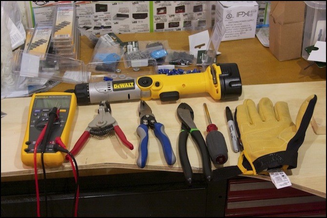
L to R: multimeter, wire stripper, wire cutting pliers, crimp tool, screwdriver, sharpie and gloves.
Above: electric screwdriver, and various connectors, track joints, and terminal strips
DC & DCC Track Bus Wiring
DCC Track bus wires are the wires from the control station (or booster) that supply track power to the circuit breakers (or directly to track feeders). DC Track bus wires are similar, except that they are connected to a DC Power Pack on one end, and the track feeder on the other. Although DCC wiring has more stringent requirements, the DC wires will be similar to permit design flexibility.
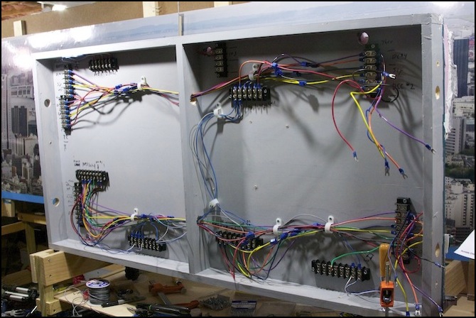
Dual Bus Wire Sets (top and bottom) with local drops (lower left, center top right) and temporary short distribution wires (blue/gray) to feeders (upper and lower edge)
For an N-scale layout the size of mine (total track circumference, and thus bus length, of about 30 feet), using a 5-Amp command station and boosters, the bus could use 16-gauge wire and still have an acceptable voltage drop. Use of 14-gauge wire provides a slight improvement (less voltage drop) and will allow for future expansion to a longer bus without rewiring. Unless you’re using 10 Amp boosters and/or really long runs, nobody needs 12-gauge or heavier wire and it’s a pain to work with, so I have no plans to use it.
I originally planned to use solid-core wire for this; its rigidity is of benefit in bus wiring, which tends to be straight, or follow a simple curve. But problems using crimp-on lugs and insulation-displacement connectors led me to replace it with stranded wire instead, and this has worked well with the addition of some nylon loops to hold long spans of the bus wires in place.
I had originally planned to use wire sold for household AC electrical use. But is has heavy and inflexible insulation, and isn’t required for the low voltages and currents in use. So I’m using something sold as “Primary Wire”. This is much more flexible (and another reason I need the nylon loops) but easy to work with.
One important aspect of wiring is voltage loss in the wire. This is simply the resistance of the wire (which depends on wire gauge as described in the table at the top of the page) times the current in amps. I’m calculating this at a worst-case, which means wires carrying their maximum rated current and heated to the worst-case temperature used in the ampacity tables of 60°C. In real-world use, loss is going to be a small fraction of that, so as long as my worst case number is reasonable, I have nothing to worry about.
The DCC bus wiring will be connected between tables using short jumpers between terminal blocks, with a break halfway around the table from the command station, so that total bus length will be about 20 feet in each direction. The voltage drop in 20 feet of 14 ga wire at 5 Amps is about 0.3 volts (the worst-case, as noted above).
Thus total worst-case voltage drop is 1.0 (track) + 0.06 (feeder) + 0.7 (dist.) + 0.3 (bus) = 2.06 volts, or 17% of a 12 Volt supply. I could reduce this significantly by adding more feeders (less track loss and shorter distribution wiring), heavier-gauge on-table distribution wire, or using larger-gauge bus wires, but none of that seems essential (note: the numbers noted here are described in more detail in the individual sections below).
Bus wiring will be twisted roughly 3.5 twists / foot, to reduce inductance (and thus noise) in long bus wire runs, as recommended on the website noted above. I haven’t had a problem with non-twisted wiring in the past, but my HO layout was smaller than this one is going to be.
The two switchable DC/DCC buses are useful for limited testing and running non-DCC trains. But there was a lot of extra work to create them as separate from the track bus(s). And there’s one serious issue I hadn’t considered when I designed them: the risk of a short. I have a crossover on the Express track, and another connecting the inner track of the Express loop to the outer track of the Commuter loop. This is required to allow a DCC train to move from storage to any track, or vice versa.
The problem is that if I ever manage to throw a crossover such that the DC track is connected to the DCC track, and then run a train across it, I’ll short the DCC power supply into the DC power supply. And I’ve had instances where the turnout control threw a crossover on power-up because of old information, and I thought it wasn’t thrown when I started running trains, so the risk is real.
At best, if my circuit breakers do a good job, I’ll probably only fry the DC power pack and the locomotive involved. At worst, I could toast several hundred dollars of DCC gear. For now I’m going to continue as planned with a healthy dose of caution when running trains, but I’m re-thinking this aspect and may eventually remove either the DC capability or the crossover(s).
This is all terribly complex, and if I were starting over with what I know now, I’d probably just run one DCC bus and require all trains to be converted, with DC testing on a table-top loop of track elsewhere.
Track and Track Feeders
Track feeders are the links from the track to the under-table wiring.
Feeders to the track can be relatively thin (22 or 24 ga) “hook up” wire. In general this will be stranded wire, but I’d likely use solid if I’m soldering it to the rails (it must be copper if I do, see the Wire section above). Kato feeders use stranded wire, and I’ll be using those to start. This will be as short as possible (but will run from the track to underneath the table), and connect to thicker distribution wires via crimped lugs and a terminal strip. Since a feeder powers at most one train if the track sections are short, current across these will be low enough (typically 0.5 to one Amp) that small wire is okay. I used similar wiring on my old HO layout and it worked well. Assuming length is no more than two feet, and current no more than one amp, voltage loss due to the feeder is thus 0.06V @ 1 Amp.
Wiring to the track needs to be frequent enough that the length of track from the feeder does not cause a significant voltage drop (voltage drops about 0.2 volts per foot in nickel-silver track at 1 Amp). It also needs to take into account the length and spacing of trains, and how many can draw power through one feeder (ideally, no more than one). Finally, if occupancy detectors are to be used, each detection section needs a feeder. That last is probably the most restrictive requirement in my case, so I’ll aim to have at least one feeder to every siding or train-length of track. Since I expect to use primarily 10-car trains, a length of about four to six feet between feeders is a good interval. At that length, and assuming one train per feeder (1 Amp total draw), I’d expect to lose about 0.8 - 1.2 volts in the track in the worst case. Call it 1.0 volts, since I probably won’t feed from the end of a six-foot section, although I may come close to it. In some places, additional feeders will be needed due to switches with gaps, and in this case several feeders may be connected to one occupancy detector.
Track feeder wires will be long enough to reach the underside of the table through one of the pre-existing wiring holes I made when building the table. At worst that would be about 2 feet, but in most cases I expect to keep it under one foot. This isn’t the way normally recommended (drilling straight down from wherever the feeder connects), but I’m doing it to keep the feeder connections under the table organized along the edge of the table, leaving the center free for electronics (I’d originally planned to put the PM42 and BDL168 here, but later moved them to a separate board that hangs down below each table to gain more room). This also simplifies things when the subway is under other track.
Feeder wires are not twisted. This is both for simplicity, and because they are relatively short and thus less of a concern as a source of inductance.
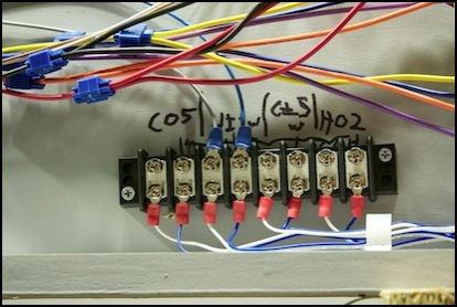
Track Feeders (blue & white to track, blue & gray to PM42/BDL168)
On-table Distribution Wiring
Between the bus and the feeder, are the electronics and the wiring connecting them all together. This includes the circuit breakers, the occupancy detectors, and the transponding sensors. This wire may be several feet long, and in some parts will carry (potentially) up to about 5 Amps. Realistically, that is unlikely in the extreme, and even so the part with that load will be a short link from the bus to the circuit breaker. Most of the wire will carry one feeder’s worth of electricity.
My occupancy detectors (BDL168), circuits breakers (PM42) and transponding sensors (RX1) were originally planned to mount to the underside of the table. This proved to be difficult to fit in the available space, so after doing the Riverside Station scene tables this way, later ones were built on separate boards and attached to the layout. See the DCC Occupancy page for details about this.
I’ve had a number of changes of mind regarding how to set up the circuit breakers, but ended up back in the same place: lower is better. Originally, with the Zephyr, I would have needed to set the PM42 trip current to 1.5 Amps, as the Zephyr’s internal breaker trips at 2.5 Amps. That was a problem due to the supposed power requirements. Once I had the 5 Amp command station, that problem was eliminated and I thought about using a higher setting. Later I realized my power requirement numbers were too high, and with my revised estimate of per-train power (typically under 200 mA without sound) a low value was no longer a problem for that reason. It is still a potential issue if there are a couple of sound-equipped trains in one section of track, which could happen once I start doing sound. On the other hand, a low circuit breaker setting makes it react faster and more reliably in a short, and limits the potential damage, so the present plan is to set all the breakers to the the lowest possible setting (1.5A). If that causes problems, I can raise it later.
As noted below, my ideal is to use 16 gauge wire for on-table distribution to feeders, to minimize voltage drop (0.02 volts/foot @ 5 amps). I could use much smaller wire (down to 22 ga, which would lose 0.08 volts/foot @ 5 amps; that’s “in air”, even 16 is undersized for constrained spaces, but I’m not running these wires in conduit), and need to use 20 gauge or smaller with some of my Digitrax boards due to the connectors used (drop of 0.03 volts/foot @ 5 amps). Since distribution wiring is likely to be only a few feet per table, I’m being overly conservative with 16 gauge wire. In part this was because I’d had problems finding crimp-on terminals that fit smaller wire, although I eventually solved that. And in part it’s because I like having a large safety margin. During construction I had some issues finding the “hook up wire” I was using in 16ga (much smaller, due to thinner insulation, than some other 16ga wire I found). I also couldn’t find 20ga wire from my usual supplier, so I use a mix of 16, 18 and 22 gauge wire for on-table distribution.
Realistically, the card-edge connectors on the BDL and PM42 are limited to 22 ga wire. While 18 ga can be used, it’s very hard to solder to the connector (some strands need to be removed to fit through the hole). I’m addressing that by limiting the length of the wires connected to those card-edge connectors, connecting to barrier strips, and using heavier gauge wire from there to the feeder blocks.
For planning purposes I’ll assume four feet of on-table 18 ga distribution wiring (half at 5 A, half at 1 A), plus two feet of 22ga 1A wiring on the power panel, for 2 x 0.0388 x 5 + 2 x 0.0388 x 1 + 2 x 0.0982 x 1 = 0.662, or roughly a 0.7V drop.
