


Regulated Voltage Car Lighting and Other Options
A second circuit for providing power protection to car interior lights with the Kato Lightboard uses a voltage regulator. The benefit over the simple capacitor circuit is that it remains at a constant intensity, or at least that was the theory. The drawback is that it stays lit for a shorter duration, and is slightly more complex to assemble. I’ve also looked briefly at a current-regulator design, which is detailed below, but I see no significant advantage to it for this purpose. See the references section on the main Car Interior Lighting page for links to similar designs by others.
Note: this design failed to work as expected, and I didn’t get continuous-intensity lighting out of the test version I breadboarded. I’m not sure why, and since the basic circuit ended up working just fine, I don’t care. I’m going to leave this page here for historical purposes, but I wouldn’t recommend this circuit to anyone.
Voltage Regulation Circuit
The idea behind this circuit was that it would maintain a steady light intensity. The big drawback I saw before testing was that that intensity would be for a shorter duration, as the regulator would cut out once the voltage dropped below its minimal level (around 6.8 volts). But when I tested the prototype, I was surprised to see that the intensity dropped as the capacitor discharged. I’m still not quite sure why.
While the circuit is not without its flaws, it works for a fairly wide range of conditions, with a minimal size and number of components and connections. Aside from the resistor, which is a problem area, the same circuit could be used for a variety of voltages and LED currents.
As in the simple circuit, a rectifier converts the DCC input to DC and feeds it to an input capacitor that stores energy. A current limiter of some kind (e.g., a resistor, although more complex techniques could be used) is required between the track and the input capacitor to limit initial current when the capacitor is charging. When track voltage is lost, the input capacitor feeds the voltage regulator with power at gradually declining voltage, until the regulator reaches its shut-off limit (around 6.8 volts).
The voltage regulator, whether fed from the track or the capacitor, outputs a steady voltage (an output capacitor is required to smooth it) of 5 volts, which is above the minimum required to light the LED, to the two input prongs of the Kato lightboard as long as there is either track power or adequate voltage from Cin. Note that on installation the input prongs of the lightboard will need to be held away from the brass input rails (a simple styrene spacer between them will do).
Problem: as currently specified, the output voltage from Cin is going to be fairly low on N-scale DCC with a 20 mA LED (no more than 9 volts, and possibly as low as 7 V, the minimum input for the regulator). This means run time for such a LED would be severely limited, in testing it appeared to maintain light for about half the time that the basic circuit maintained an acceptable level.

Parts List (all costs in quantity 100+)
- Rectifier: Fairchild Semiconductor 58K1812 ($0.219)
- Regulator: Fairchild Semiconductor LM78L05ACZ, ($0.113)
- R1: Multicomp MCMF03WJJ0101AA9 100 Ohm, 3 Watt, 500V 5% ($0.084)
- Cin: Panasonic EEUFK1V122 1200 μF, 35V, 12.5mm x 25mm, 5,000 hr endurance ($0.834)
- Cout: Multicomp MCMHR63V104M4X7 0.1 μF, 35 V ($0.034)
Total circuit cost: $1.28 per car (in quantity 100+)
Additional details on how I selected the components are to be found below, after the alternate design.
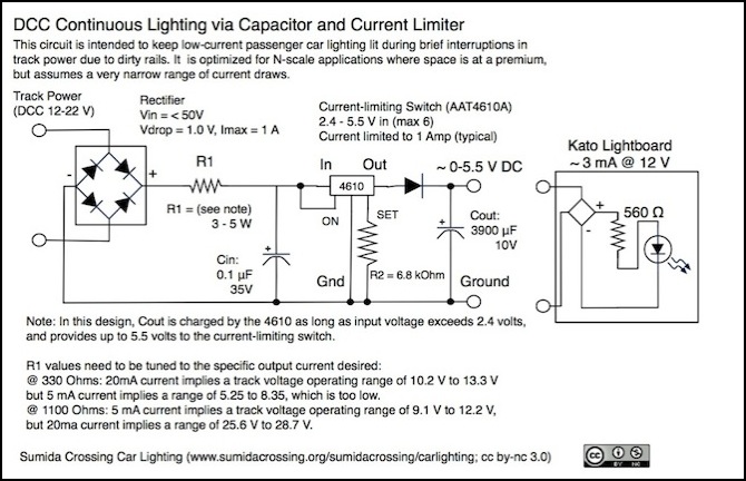
Current-Limiter Circuit
I worked up an alternate design, to see how use of a current limiter alone would work. I didn’t take this all the way to a polished design, as it has several significant negatives compared with the voltage regulator approach, not least of which is the variable output.
This design can be used if the output current is known in advance. It omits the voltage regulator, allowing the LED voltage to fluctuate (but this is cushioned by the capacitor, so it only varies as the capacitor drains and charges). However, as it depends on a specific value of R1, which in turn depends on the current to keep its voltage drop in check, this only works for a narrow band of currents. This means that it needs to be tuned for a specific lightboard demand, and it also will not work on both “N-scale” and “HO-scale” DCC track voltages (and many N-scale trains are run on “HO-scale” DCC systems). As currently detailed, this is an inadequate design.
It may be possible to find a current-limiting switch that operates over a wider or higher band, which would make this design more practical (but I couldn’t find one easily). If the switch can be optimized, and R1 eliminated, the waste heat production would be less than in the voltage-regulator design, although the more complicated wiring will be an issue (since I’d need to make quite a lot of these). Alternatively, the resistor could be replaced with the voltage regulator from the other design, but this would require an additional capacitor to filter the regulator’s input, and the resulting circuit would have a significant number of connections to make, again an issue due to the number to be made.
This design (at present) needs R1 to drop the track voltage to an acceptable level. The current limiter then charges the Cout power storage capacitor (Cin is needed to smooth the input current). The switch will be active whenever the input voltage is above its minimum, and off otherwise. The diode on the output is required to prevent reverse current from the capacitor when the switch is off, which could damage the switch. Output to the LED will rise from 2.4 volts at initial power-up to an eventual 5.5 volts, and fluctuate slightly below that as track voltage is interrupted. At power-off, voltage will decline as Cout drains, until the LED no longer passes current.
The necessary current limiter is not a common part, and availability is uncertain. There also don’t seem to be others this simple on the market; most are large IC packages designed with flexibility of application rather than size in mind (i.e., they are in big cases with lots of pins that need to be connected to something).
An advantage to this circuit is that the lower voltage required by the current-limiting switch allows use of a larger capacitor within the space constraints, which means a longer runtime. However the lower starting value also means that as the capacitor drains, the lights would become fairly dim. All-in-all, this alternative does not seem to be attractive. It’s too complicated, and the value it adds in longer runtime is offset by more heat production (in continuous use of R1) and dimmer lighting.
Voltage Regulation
The National Semiconductor 78Lxx family provides the right voltage range and is readily available. There are several models available in this product line using the TO-92 (three-lead, round; 4.19mm x 5.2mm, 5.2mm long) case:
LM78L05ACZ: Vin (min) = 6.7 V, Vin = 7-20 V, Vin (max) = 35 V, Vout = 5.0 V
LM78L62ACZ: Vin (min) = 7.9 V, Vin = 8.5-20 V, Vin (max) = 35 V, Vout = 6.2 V
LM78L85ACZ: Vin (min) = 9.9 V, Vin = 11-23 V, Vin (max) = 35 V, Vout = 8.5 V
LM78L09ACZ: Vin (min) = 10.7 V, Vin = 11.5-24 V, Vin (max) = 35 V, Vout = 9.0 V
LM78L12ACZ: Vin (min) = 14.5 V, Vin = 11-23 V, Vin (max) = 35 V, Vout = 12.0 V
For prototyping I used an NTE 977 I could find locally, which has nearly identical specifications to the NS LM78L05ACZ.
Note: there’s also a surface-mount case which might be even better from a space perspective than the TO-92. It’s 1.285mm x 1.285mm x 0.850mm. Only the LM78L05ITP and LM78L09ITP are available in this style. Aside from size, Tmax = 85 °C and θJA = 230.9 °C/W, these have the same specifications as the TO-92 (ACZ) part. However, these are specialty parts not ordinarily stocked, and the Tmax limit has implications for the possible operating voltage range (discussed in the heatsink section below) so I’m planning to use the TO-92.
LM78L05ITP: Vin (min) = 6.7 V, Vin = 7-20 V, Vin (max) = 35 V, Vout = 5.0 V
LM78L09ITP: Vin (min) = 10.7 V, Vin = 11.5-24 V, Vin (max) = 35 V, Vout = 9.0 V
Keeping in mind that “nominal” N-scale track voltage of 12 V DCC RMS may be as low as 10 volts, and that the rectifier will drop about 1.0 V with additional loss in the resistor (depending on LED current), this needs to work on 8.8 V or less. Thus the LM78L62AC is a possible choice. It can operate on up to 20 V, well above what a DCC system used for N-scale should output, and it can tolerate well above the maximum allowed by the standard. However, as we’ll see below, there are additional voltage losses to consider, and the 5-volt regulator may be preferable as a result. That part would also be required if I wanted to use a surface-mount case, as the LM78L09ITP needs too much voltage.
LM78L62ACZ:
θJA =180 °C/W
Vout = 6.2 V
Recommended: Cin = 0.33 μF, Cout = 0.1μF
Tmax = 125 °C
LM78L05ACZ or LM78L05ITP:
θJA = 180 °C/W for TO-92, 230.9 °C/W for SMD
Vout = 5.0 V
Recommended: Cin = 0.33 μF, Cout = 0.1μF
Tmax = 125 °C, 85 °C for the SMD case
The input and output capacitors are required to smooth the current. The output capacitor is particularly important, as the regulator can produce a spike at power-up that can potentially damage the LED being driven by the circuit. The input capacitor in my preferred circuit will be the large one, providing power to the regulator as it discharges from near track current down to the operational limit of the regulator.
Since the effective voltage charging the capacitor may be as low as 9 volts after rectification on dirty track, the lower-voltage regulator is going to provide a longer run time, due to its 7 volt (6.7 V minimum) input.
These are made by both National Semiconductor and Fairchild Semiconductor, with Fairchild having the lower cost (Fairchild Semiconductor LM78L05ACZ). The output voltage can vary by 5% on this part, which is negligible.
Computing Heatsink Requirements
The rate at which a heated object cools is proportional to the difference between its temperature and that of the surrounding air, meaning that the warmer the surrounding air, the less efficient cooling is. That’s Newton’s Law of Cooling. We need to assume a fairly warm surround, as air cooling of parts crowded into a small passenger car with limited airflow won’t be too efficient.
A semiconductor case on its own can dissipate heat at a certain rate. A heatsink is required when this is too low a rate to prevent the semiconductor’s junction temperature from exceeding its maximum allowed operating temperature (Tmax).
P = (Vin - Vout) x I
TΔ = Tmax - Tambient
θ = TΔ / P
Assume Tambient = 35 °C
Assume I = 20 mA (worst case normal LED)
Assume Vin = 20 V DC (worst case input voltage after regulation)
Assume Vout = 5 volts (the worst-case output)
θ = (125 - 35) / ((20 - 5) x 0.02) = 90 / 0.300 = 281.25 °C/W at 35 °C ambient.
As this is above the TO-92 case’s rating of 180 °C/W, no additional heat sink is required to keep the regulator at an acceptable temperature across the possible voltage range.
Power dissipation (the “P” above):
LM78L05AC: 320 mW @ 21 volts, 120 mW @ 11 volts
LM78L62AC: 284 mW @ 21 volts, 84 mW @ 11 volts
For the SMD version:
θ = (85 - 35) / ((21 - 5.0) x 0.02) = 50 / 0.32 = 156.25 °C/W @ 21 volts in 35 °C ambient at 20 mA.
This falls below the θJA =230.9 °C/W of the SMD case, indicating that a heat-sink would be required to operate the 5-volt version at maximum voltage in this environment. However, at 16 volts, the result becomes 227.3 °C/W, just below the threshold, and adjusting the maximum permissible temperature to 30 °C yields:
θ = (85 - 30) / ((16 - 5.0) x 0.02) = 55 / 0.220 = 250.0 °C/W @ 16 volts in 30 °C Ambient at 20 mA.
Maximum power dissipation has been reduced to 220 watts due to the lower maximum voltage, but is otherwise identical to the TO-92 case (it depends on voltage and current, not ambient temperature). It does mean that the SMD version would be limited to a maximum voltage of 16 volts however.
There’s an assumption in the above, and it’s a big one: that ambient temperature around the electronics will stabilize at something not too far above room temperature (30 or 35 °C). If you assume it stabilizes at something like 50 °C, then the TO-92 will go into thermal shutdown at 20 mA, even using 14 volt DCC and the 6.2 volt voltage regulator (the best possible case). There’s still a safety margin from the probable lower real power draw of the Kato LED lightboard (which appears to be below 3 mA, not 20), which would allow even the 5-volt regulator to work at 50 °C.
θ = (50 - 30) / ((16 - 5.0) x 0.005) = 20 / 0.055 = 363.6 °C/W @ 16 volts in 50 °C Ambient at 5 mA.
So if it’s well cooled, this circuit (using the TO-92) should work even at extreme voltages. It may be marginal at higher track voltages if cooling is a problem. But for the voltages and amperages I anticipate on my layout and with the Kato lighting kits, or even if I visit someone with an HO-style DCC system operating at 16 volts, the regulator shouldn’t go into thermal shutdown even on a warm day.
However, this does mean that the voltage regulator isn’t really the right one to use if you anticipate operating at higher voltages, and you’d be better off picking a model with a voltage range more closely aligned to the expected environment.
Maximum Allowable Case Temperature
Another issue to be concerned with is damage to the vehicle containing the device. The melting point of polystyrene plastic is 240 °C, however it is a glassy solid which will flow (deform) if heated above 95 °C (that’s what wikipedia says, but I’ve seen other numbers as low as 77 °C). I think that at 20 mA the dissipated heat will be acceptable, but I’m not certain of that yet, and the Tmax of the voltage regulator is well above either of these limits, so there is the potential for it to get too hot.
This is complicated by the fact that the installation environment is a closed car, open only via doorways at the ends, so replacement of the air will be limited, and most cooling will ultimately be radiative (the case will heat the air by convection, which will heat the body shell of the vehicle in the same manner, which will then heat the external air. I don’t think this means that ultimately the body shell would be raised to something close to the exterior temperature of the case, as the body has much more surface area to radiate with (and mass, which will make it slow to rise), but there could be localized heating.
I need to do a long-term test using a small styrene box to see what kind of temperature I get before I put one of these in an expensive model.
Inrush Current Limiting
When power is first applied to the track, capacitors will draw power at a high rate as they charge up to the voltage of the track. This creates a short-lived high current (called an “inrush current”). This problem increases with larger capacitors (and is severe with supercapacitors). With a number of cars equipped with this lighting circuit on the same section of track, the aggregate current may be high enough to trip the circuit breaker.
The inrush current into a capacitor is described as:
J = 0.5CV^2
where J is the energy in Joules, C is the capacitance in Farads, and V is the voltage in volts.
for a 470 uF capacitor at 22 volts, this is 0.114 Joules. At the more likely 11 volts, this is 0.028 Joules.
There are several methods available to limit inrush currents. I’m going to use a simple resistor, but I’ll note the other options.
Thermistor:
Causes short-term voltage loss only during high charging current
Somewhat bulky
Produced heat (like a resistor)
cool-off period required between uses (not compatible with DCC circuit breaker behavior)
The big problem with this one is that it needs a cool-down period between uses. That’s not compatible with self-resetting circuit breakers that could be repeatedly tripped (once something tripped the breaker twice in quick succession, you’d have to take the train off the track to get the track to power up, and let the train cool down for a minute or so before putting it back on the rails).
MOSFET (such as AAT4610A)
Needs external resistor and capacitors (1 μF input, 0.47 μF output) in addition to those required by the regulator.
Usually large, although this model is apparently quite small (designed for use in memory cards).
Note: the AAT4610A is a good size, but is limited to 5.5V; it could work on the output side of the regulator, if a smaller model (ie. the 78L05) were used, and this is the logical place to use it with a supercapacitor. The AAT4684 might work, but needs even more external circuitry. Ultimately, since I’m not using a supercapacitor, the added cost and complexity compared to a resistor doesn’t seem worth it.
Resistor:
Compact
Constant voltage loss
Heat production when passing current
The resistor does not need to be between the track and the regulator, only between the capacitor and the positive supply line connecting the rectifier to the regulator, so it need not produce heat except when the capacitor is first charged or is discharging, unless you also need it to drop voltage for other reasons.
The important formula here (Ohm’s law) is:
R = Vp / Imax (resistance to limit charging current to Imax at peak voltage Vp)
and
Vdrop = R x Idraw (voltage drop across resistor with LED drawing Idraw Amps)
The size of the resistor is computed based on the maximum desired current, and the peak voltage, as the capacitor initially acts as a short-circuit. Assuming fifteen cars on a given 3 Amp circuit breaker track section, inrush current must be held to less than 0.2 amps each, and lower is better. For 22 volt (worst case DCC) and a 0.1 Amp peak current, the required resistance would be 220 ohms (22/0.1=220). For a 12 volt, 0.1 Amp peak current, it would be 120.
The converse is that a high resistance causes a significant voltage drop on output. At 20 mA, the 220 Ohm resistor would lose 4.4 volts (220 x 0.02 = 4.4), too much to enable the 7-volt input of the regulator to be sustained for long, if at all. At 5 mA, it would only lose 1.1 Amps so it could be used if the circuit was optimized for the Kato board. A lower value optimized for N-scale DCC systems of 12 volts, but with reasonable performance on typical HO-scale 14-16 volt systems is preferable. A 100 ohm resistor would allow 0.12 Amps per car at 12 volts, 0.16 at 16, and 0.22 at 22 volts. With a 15-car train, this probably would not trip even the 14-Volt Zephyr’s 2.5 Amp circuit breaker (0.14 x 15 = 2.1 Amps) and it’s a comfortable 1.8 Amps at N-Scale’s 12 volts.
The resistor must be able to dissipate the maximum power (volts times amps) put through it. This would be 16 x 0.16 = 2.56 Watts at the worst case (oversized HO DCC system), and 12 x 0.12 = 1.44 Watts at 12 volts. Resistors larger than 3 watts begin to get rather large, so this is probably a good choice (but note that at 22 volts, the resistor would need to dissipate 5 watts, and this could be enough to cause it to fail, damaging the vehicle if the train were placed on such a system; if a 5 watt resistor of reasonable size can be found, that would be preferable). Note however that since the resistor is placed where it only draws current during drain/charge activities, and the 0.1 amp inrush current is both very brief (~5 milliseconds) and only happens at initial placement, there is likely a large safety margin here.
With a 100 Ohm resistor, and a 20 mA normal current, there will be a 2 Volt drop across the resistor. This will be just half a volt if the actual draw is 5 mA. At the worst-case 10 Volt track current (and remembering that the rectifier drops this to about 9 volts), this will limit input voltage for the regulator to at best 7 Volts @ 20 mA, which is too low. This means that a resistor is a poor choice if I really want to drive 20 mA LEDs, although it should work for the Kato lightboard.
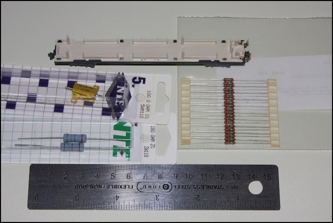
In the photo above, several standard resistor sizes are compared. The set of brown ones on the right are the 1W 150 Ω resistors I ended up using for the simple circuit diagram. The gray ones on the lower left are the 2W 180 Ω ones I used on the prototype board. And just for comparison, the gold one is a 5W 100 Ω model I picked up in case I decided to built the full-voltage version of the design.
