


Arduino Power
Most tutorials about Arduinos don’t really talk much about their power characteristics. These are aimed at novices and non-technical hobbyists and don’t want to scare them off with a bunch of numbers and math. That’s fine; most people building simple things with Arduinos don’t need to worry about power budgets, or voltage stability or heat. But if you’re going to push the bounds of what an Arduino can do, it’s important to know where those bounds are. Crossing them can toast your Arduino, and that gets expensive.
The following material was collected from a number of online sources. See the References at the end for some more general sources, and I’ve tried to link directly to specific references where I thought it helped.
And, as always, I’m a hobbyist, not a professional. What’s written here is correct to the best of my knowledge, but as I’ve repeatedly demonstrated that knowledge is often more limited than I think it is. Do your own reading with this as a guide, and draw your own conclusions about what the limits are. Maybe you’re more willing to take risks than I am, maybe less. In any case, if your Arduino bursts into flame as a result of actions based on what you read here, don’t blame me. Use this information at your own risk.
Basic Do’s and Don’ts
Here’s a list of simple guidelines, which I’ll cover in more depth below.
Do:
- Use an external (wall wart) DC power supply, preferably a “regulated” 9V, 500 mA or more one.
- Drive things that are low power, like external controllers for LEDs. Arduinos are for controlling circuity, not driving it.
- Put “safety” resistors (typically a few hundred Ohms) on all pins that will be used as outputs to limit current.
- Keep your circuit design below 100 mA of current drawn from the Arduino.
Don’t:
- Use an external AC power supply.
- Use a power supply less than 7V or more than 12V.
- Connect anything other than exactly 5V (or a circuit needing 5V) to the “5V” pin.
- Ditto for the “3.3V” pin.
- Wire up an external supply to Vin and Ground backwards (get the polarity wrong and say “goodbye Arduino”).
- Wire anything to Vin if you’re using the jack for an external power supply (more ways to say “goodbye”).
- Use an unregulated power supply (possibly safe, but not a good idea).
- Wire LEDs directly to pins without a resistor (if you do, say “goodbye Arduino pin” at a minimum).
- Wire pins directly to ground or through things that don’t provide much resistance without adding a resistor.
- Wire pins to each other without a resistor between them.
- Don’t use more than 20 mA per pin if you can avoid it (that’s one LED), 40 mA (two LEDs) is an absolute limit.
- Don’t wire up something as power-hungry as a single LED on every pin, or even half of them.
Power, Voltage and Current
The basics are pretty simple. Most Arduinos operate on 5 Volts internally (some use 3.3 V and some of the ones designed for wearable use are more flexible than that). I’m going to focus on the 5V models, as those are, I think, most useful for model railroad projects, but if you’re mostly driving LEDs, a 3.3 V model may be more efficient (you need smaller resistors between it and the LEDs, so there’s less wasted power discarded as heat in resistors).
The Arduino takes two kinds of input power: USB or a directly-wired supply. USB is typically limited to 500 mA if driven from a powered hub or a computer, and 100 mA if driven from a non-powered hub. So that’s an important issue to be aware of: don’t plug your Arduino into an unpowered hub unless you aren’t doing much with it.
USB is handy for testing new software (since you need to keep loading it, and print commands to the serial output are a useful way to debug problems), and it supplies enough power for some basic circuitry during such testing.
A wired supply will be needed for any application where you want to be sure the power is stable (power from a computer or hub will vary depending on the demand from other devices) and it’s a really good idea if you might need more than ~100 mA (see the Volts section below). A wired supply will also be needed if you want to unplug the computer and leave the Arduino running, or want to install the Arduino under the layout and not connect it to a computer at all after you’ve programmed it.
Older Arduinos had a jumper on the board to select where the power was taken from. Current versions do this automatically.
Volts and Power Supplies
The Arduino wants 5 V internally, but it can work with other voltages and when using external supplies it must have a higher voltage. That has a cost in wasted power and heat.
Note: the Arduino has a “5V” pin (and also a 3.3V pin) adjacent to the ground pins. These can be used for an external supply at exactly the specified voltage. This bypasses the voltage regulator, so connecting a higher voltage supply will likely damage the Arduino (at least the CPU, and possibly the voltage regulator). If you want to wire up a higher-power supply and have it regulated without using the jack, use the Vin pin for its positive line (and one of the Ground pins for negative). But get the polarity right; wire it backwards and the Arduino goes “poof”.
For a 5V Arduino, the normal operating range extends up to 5.5V. Supplying more than 6.0V will damage the chip (typically a voltage regulator allows higher voltages to be present on USB, but not on the “5V” pin, see below). For a 3.3V Arduino the range is obviously lower, but this will depend on the specific model used. The M0 allows up to 3.6V in normal operation, and voltages above 4.1V applied directly to the 3.3V pin will damage it. High voltages applied to the I/O pins can also be problematic; although these are protected, the protection has limits, see the Interfacing section.
A USB connection nominally supplies 5V, but it can actually be as low as 4.45 V and still be “correct”. The Arduino will have to draw extra current from an undervoltage supply to compensate and so the current limit on the Arduino will be lower than the theoretical limit of USB (which is nominally 500 mA although you really don’t want to depend on the supply being able to provide that, as many real-world supplies can’t; even 100 mA could be problematic). The Arduino’s on-board regulator will limit it to 800 mA from the power supply, although the limits on the microprocessor (and its output pins) are more severe.
An external supply (2.1 mm jack, center pin positive) can safely be anything from 7 V to 12 V and the Arduino’s voltage regulator will convert that to 5 V for internal use; the supply has to be higher, because there’s always some guaranteed loss. A typical “wall wart” transformer can provide around 600 mA of current, although these vary a lot. You also need to know if the supply is “regulated” or not. A non-regulated supply will vary as the wall voltage varies (lower during brownouts, higher at times when residential power use drops, like late at night). Regulated supplies usually cost more, but you don’t have to worry about them providing too much or too little voltage. A non-regulated 9V supply is pretty safe however, and may be cheaper. Sparkfun sells a regulated 9V, 650 mA supply (TOL-00298) for US$5.95, and that looks like an ideal choice to me.
The Arduino can operate on a 6V to 20V supply, but at low voltages it may misbehave, and at higher ones it’s producing a lot of waste heat that could cause it to eventually fail. They recommend staying within 7 to 12 Volts to be safe.
Note: oddly, a tutorial on Arduino’s site about external power supplies says that the minimum voltage must be 9 V. I think that’s just being overly cautious for safety. It’s probably good advice in general.
Something that may not be obvious here (I overlooked it at first): the higher the supply voltage, the more work the Arduino’s voltage regulator needs to do to convert it to 5V, and the more heat that’s going to produce. It’s also less “green” in the sense that you’re basically throwing away power as heat (depending on the design, though, the wall wart may throw it away anyway, so don’t lose too much sleep over that aspect). This is why a 9V supply is somewhat better than a 12 V supply (and a regulated 5 V supply bypassing the on-board regulator would be ideal, but those aren’t common).
If you have a regulated 5V supply, connecting up to the “+5V” pin is even better than using the jack, since you’ll avoid wasting power (and producing heat) in the voltage regulator. This is mainly useful when you use a “regulator shield” that clips onto the Arduino and connects via the +5V pin. These are typically used with lithium-ion rechargeable battery packs (in robots, for example) or hybrid solar/battery applications. This might be handy if you were putting an Arduino inside a train (likely O scale or larger, although a Pro Mini might fit in an HO train).
Batteries
On a model railroad layout, you should be able to power an Arduino from an AC adapter. But it is possible to use batteries, with some restrictions. First, don’t use a 9V battery. It might seem ideal, but they don’t hold a lot of power compared to other kinds, and you lose a lot of that in converting it to 5 V (close to half goes away as heat in the regulator). At 100 mA load, a 9V battery might be good for a couple of hours before it needs to be replaced; a rechargeable one would need to be recharged very frequently, perhaps in under an hour. If you design a very low-power circuit, you might be able to use a 9V battery, but there are really much better solutions.
If you use AA batteries you need a 6-cell battery holder (there are 4-cell ones available “for Arduino”, but these only work for a 3.3V Arduino). AA cells do have a lot more power than a 9V cell though, so they are a practical source. Expect to replace them often however (and rechargeables may still only give you a few hours between charges), although that’s highly dependent on load. The ATmega CPU alone could run for 9 hours on just one battery with a step-up regulator (so about 35 hours with six), but that doesn’t count other circuitry on the Arduino board, or anything you add external.
You can actually use fewer than 6 AA cells, even as few as just one, if you use a voltage regulator chip that will boost the output voltage. This draws more current, and hence the battery will drain faster, but for very space-constrained locations it might be an acceptable solution (see the References section for entries about battery power).
You can also power an Arduino using a combination of rechargeable batteries and solar cells. That doesn’t seem likely to be useful for most model railroads, but it could be very handy for a garden railroad (e.g., to control a crossing gate). See the References section for one blog post on hybrid power (the “off the grid” one).
Current
As mentioned above, supplies that can provide several hundred milliamps are common, is that the limit on the circuits you make with an Arduino? No, there are several other limits affecting how the Arduino can draw power.
First, be aware that any single output pin on the Arduino has a 40 mA limit. That’s enough to light two ordinary LEDs or a really tiny bulb (most “grain of wheat” bulbs common to model railroading are likely to draw more like 60 mA, so stick to LEDs unless you add external light-driver circuitry). Although that’s the limit, good advice is to be conservative, and not try to drive more than one LED per pin (at a time; multiplexing several is fine as long as no more than one would be on).
Second, the pins are arranged in “ports” (sets of pins) on the ATmega chip driving the Arduino. And each port has a maximum limit of 100 mA on input or 150 mA on output, so you can’t drive every pin at 40 mA (see the DC Characteristics section of the relevant ATmega datasheet).
You can get the detail about pins and ports for a specific Arduino by looking at the schematic for it on their site, which will list both ATmega port and Arduino pin numbers. For example, on the Uno pins 0 - 7 are associated with Port D (also known as the IO port) and pins 8 - 13 share Port C with the AREF, SCL and SDA pins. The six analog pins are associated with Port C. And no, I don’t know why there’s no Port A, but there isn’t. Other Arduinos based on the ATmega 168 and 328 chip are probably the same, but I haven’t checked. The Leonardo, based on the ATmega32U4, is not the same.
But all the power to all the pins is going through the ATmega microprocessor chip, and per its datasheet, it is limited to 200 mA. That’s not a number you see written down too often (I found it while looking through the data sheet for something else, and it’s what started me to researching the info for this page). That’s a lot less than the 500 to 650 mA that the power supplies can provide, and it’s a hard limit. Try drawing more than that, and something’s going to give, and it’s probably going to be the ATmega CPU chip.
Uno’s have socketed CPUs so you can replace them. Some other models don’t and you’d have to replace the whole Arduino.
Now it’s not always that limited. Apparently versions of the Uno that use a surface-mount chip (not the one in a socket), like the Sparkfun Uno R3-SMD (DEV-11224), have twice the total power handling ability (400 mA), although there are the same per-pin and per-bank limits. And the Mega 2560 has a limit of 800 mA (again with the same per-pin and per-bank limits).
Also, whether the limit is 200 mA or 800 mA, the manufacturer cautions against driving the chip at the maximum for an extended time, as it could lead to overheating and damage.
The Survival Guide referenced below recommends you limit your use to half the CPU’s maximum; some of that 200 mA is going to the chip (about 16.5 mA) and other parts of the Arduino (a few mA). You can probably use more than 150 mA, but planning for less seems like a good idea to me. It may seem relatively small to only use 200 mA of a 600 mA supply (you can still use the rest by tapping the +5 V pin on the Arduino’s header; the voltage regulator is safe to 800 mA), but the purpose of an Arduino is to control things, not drive them directly. I’ll violate that in some of my designs, e.g., by driving multiplexed LEDs directly, but I’ll do so very carefully and with full awareness of my power budget and where the limits are.
Note: I’ve seen comments about connecting a 1 Amp (1,000 mA) power supply via the Arduino’s jack. Don’t do that and expect to use it. The limit on the typical voltage regulator used on the Arduino to convert the external supply to +5V is 800 mA (and it’s going to be quite hot at 800 mA). There may also be additional limits due to circuit board traces: I’ve seen comments that the +5V pin is limited to 200 mA, but that may be a reference to the microprocessors use of the pin for an external power source.
Grounds
Arduinos aren’t grounded, in the sense of having a safety ground to the wall. They do however have a ground pin that provides the 0 Volt reference level, and you need to be aware of how it works in circuits.
First, if you use more than one power supply connected to a single Arduino and its associated circuits (or two or more Arduinos wired together), verify which output is ground on each (use a multimeter) and TIE THE GROUNDS TOGETHER (that means wire them together as close to the wall wart as is practical; connecting to the ground pin on the Arduino or a shield is acceptable). Circuitry with more than one idea of what “ground” means just isn’t likely to work well.
Ground is where all power ultimately flows to complete a circuit. From there, it goes back to the voltage regulator or other source. If you connect to the ground pin on the Arduino, you have a fairly direct connection. The ATmega CPU also connects to ground, and when you put a pin in LOW state, you’re effectively connecting it to ground through some internal resistance. At 20 mA load, a pin in LOW state may be as high as 0.9 V relative to the power supply ground due to that internal resistance. That’s enough to activate some circuits, so don’t assume LOW is equal to ground when designing circuits. It might be, but it might not be.
Any resistance in a circuit (even the resistance of wire) creates a voltage differential. For this reason it’s a good idea to bring the ground side of any circuitry back to the ground pin in the most direct (shortest wire) manner possible. The ground wire could be (but probably isn’t) carrying 650 mA, which would require a 28 gauge or larger wire. But in most cases it’s probably carrying only a couple-hundred mA, so you could use smaller wire (down to about 32 ga; I wouldn’t use smaller).
You can get “interesting” behavior in circuits where something other than the nominal ground line has a lower voltage. It’s usually best to avoid chaining one set of circuits through another. They could both share a single ground line if necessary, but each should connect to it at one point. Ideally, wire both back to the ground pin on the Arduino separately.
Wire
Wire used on breadboards tends to be fairly large, and that’s fine for prototyping circuits. You can use much smaller wire in Arduino circuits, particularly ones drawing very low current. The limiting factor in most cases for model railroading will be the wire’s tendency to break if too small, particularly for solid wire (like magnet wire) that is repeatedly flexed. You might have more problems if you were using the wire for higher currents (like a motor), but I’ll limit my comments to the kinds of currents you’d get from an Arduino (tens of milliamps, in general).
Even for fairly long wires at 30 ga, voltage loss in the wire due to resistance is negligible. Copper wire at 30 ga has a resistance of about 0.3 ohms per meter, and even 10 m of wire at 20 milliamps just loses 0.06 Volts. Longer and smaller wires raise that, but as long as you aren’t trying to drive multi-hundred milliamp DC motors through magnet wire the length of your layout (which would be silly), you’re not likely to run into problems. The following table shows some typical resistances (computed from the specifications for typical wire).
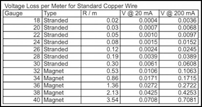
Small Wires: Resistance and Voltage Loss per Meter at Low Currents
For wiring in really constrained spaces (like inside a signal mast) smaller magnet wire makes a lot of sense. Even 40 gauge magnet wire can carry the current from several 20 mA LEDs with no problem. I wouldn’t recommend using it by the meter, but a three-LED signal’s common line with three parallel 20 mA LEDs drops just 0.21 Volts per meter, so a few centimeters in a signal mast is negligible.
Reference
3 Ways to Power an Arduino Off-Grid
A brief blog post about ways to power an Arduino without using a wall-wart. It’s mostly about use of photovoltaic (solar) cells, and the company posting it sells them, but that doesn’t make it a bad idea.
10 Ways to Destroy an Arduino
This interesting page provides a helpful list of things not to do. The author sells an Arduino that’s been “ruggedized” to protect it from a lot of common wiring mistakes that can damage an Arduino. I have no experience of these, but it sounds like a really good idea.
Arduino Pin Current Limitations
This summarizes the contents of the ATmega data sheet regarding the current limits of the Arduino’s CPU.
Arduino Product Page
This page has links to a page about each model of Arduino, listing some basic specifications. But more importantly, most of those pages have links to schematics for the Arduino board plus a link to the relevant ATmega datasheet.
Arduino Power Consumption Study, by Igor S. Ramos
This describes a brief experiment to see how much power an ATmega chip used at different voltages and driving frequencies (at 5V and 16 MHz it used 16.43 mA).
Arduino Survival Guide - Workbench Edition, by Ed Nisley
This is a wonderful compendium of good advice (in a PDF document you can download and keep handy) on using an Arduino and where the limits are. Also see his blog for other useful tips, like why you never wire a LED to an Arduino pin without a resistor.
Battery Powered Arduino
A short article from an electronics supplier about battery power for Arduinos, including several products that use regulators to power a 5V Arduino from smaller batteries.
Fueling Your Arduino, Why You Should Use an External Power Breakout, by Adrian Carter, Australian Robotics
A nice article on powering the Arduino, with thermal images showing what parts get hot (and how hot) in use. The gist of it is that even at 9V the voltage regulator is getting quite hot, and using an external regulator board that supplies 5V, bypassing the on-board regulator, is a better idea. I’m not sold, but it is a strong argument in favor of using a 9V wall-wart over a 12V one.
