


Arduino Controls and a Simple Throttle
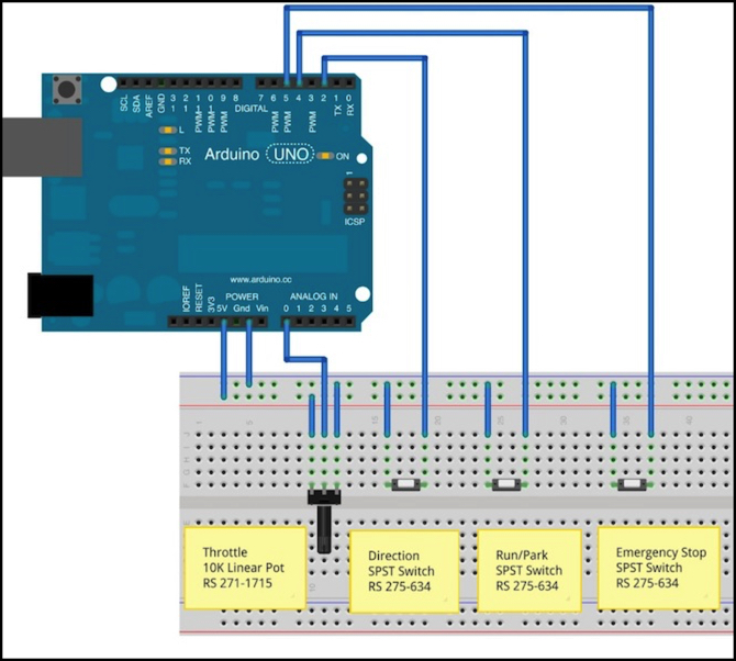
Diagram created using Fritzing (note: motor shield not shown)
My obsession with small computers continues. I promise I’ll get back to actually posting about trains in the not too distant future. Although since today’s post is about making a DC power pack from an Arduino, it’s about trains in a sense.
The Big Project
Having covered the motor control and the sensors, my next step in creating the automated two tram controller was to deal with the very small number of controls I need to have. In my original design, the plan was to have just three pushbuttons:
- Run: when pressed, the trains would start to move.
- Park: when pressed, the trains would return to their starting locations so the system could be turned off.
- Emergency Stop: when pressed, the trains would come to an immediate stop until run was pressed again.
And all three were to be “on when pressed, off when released” pushbutton switches. I was already thinking this needed to be changed, and when I started playing with switches I became even more convinced.
First, “run” and “park” are two sides of the same coin: I could implement this with a simple on/off switch. When on, the trains run, when off they return to their parking locations. The Arduino software continues to run until power is removed, of course. My original thought was that “run” could clear both the “park” and “emergency stop” conditions, which was why it needed to be separate from “park”. But on further thought, “emergency stop” can equally well be an on/off switch: when on, trains stop. When off, if the other switch is still in the “run” state, resume running, if in the “park” state either remain motionless, or perhaps return to the parking locations and then stop.
I could actually simplify this further, with a Park/Run/EStop control using a three-position rotary switch and some resistors (Radio Shack’s 275-0034 6-position switch is overkill, but would work). With that, I’d only need to use one analog pin. I’m still considering that for the final design. But for now, I’ll stick with simple toggle switches.
There are two benefits to using toggles versus “on while held” button switches: first, I eliminate a switch, since I need two toggles rather than three pushbuttons. Second, I avoid using those pushbuttons, which have proven to be problematic in my testing. They tend to “bounce” for a long time, and they may remain “on” only for a fairly brief time, making it hard to avoid all bounces and still reliably tell that they were pressed in the first place.
The other control I wanted to add was a way to customize the top speed of a train (or trains, really), so the different models could be made to run at similar (and prototypical) speeds. I don’t want one train rocketing down the tracks while the other creeps along, even if they have very different motors and gear-trains. So I’m going to add a pair of potentiometers, used as “tram #1 max speed” and “tram #2 max speed” controls. And note that these are for the trains, not the motor shield A/B outputs. At various times each tram will be controlled by one or the other.
But First, Something Simple
My first step was to create a simple throttle that used one pot, three switches, and one motor control to run a train on a simple test track. This gives me a proof-of-concept example that ensures I really understand what I think I understand (always a concern with me and electronics).
Before I could do that, I needed to figure out how to work with these controls. So I created a number of very simple “read the control and print what you see” test programs, and tested a number of switches and potentiometers, while in some cases using my oscilloscope to see what was going on.
In the course of that, I decided that most of what I was doing was fairly general-purpose, and could be reused for other projects I might do in the future (a switch is a switch, after all). So I created an Arduino sub-section in my Electricity for Modelers section, with pages for the different kinds of controls. I may eventually move some of my material on Sensors to there as well, but for now it remains with the other pages specific to the Tram Controller project.
With that out of the way, I took what I had learned, and came up with a circuit design (see graphic at top of post) and wrote an Arduino sketch to read the controls and use by motor shield control library to run a train using motor output A.
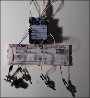
seeed v2 shield running a train
My simple throttle uses four controls:
- A 10K ohm linear potentiometer to set the speed from zero to full.
- A SPST toggle switch for direction (“on” is one direction, “off” is the other).
- A SPST toggle switch for Run/Park (set to “park”, or “off”, it gradually slows the train to a stop)
- A SPST toggle switch for Emergency Stop (set to “on” it immediately cuts the throttle to zero).
Note: the toggles are implemented using the internal pull-up resistors of the Arduino, which simplifies the wiring.
All three toggle switches are Radio Shack 275-0634 “SPST Lever Toggle” switches, or equivalent. The pot is a Radio Shack 271-1715 or equivalent.
An external 12V, 600 mA power source, like this one, is also needed (a really small train might work off USB power, but it’s a good way to blow the USB port on the computer, so I wouldn’t try it).
As written, this program will work with an Arduino Uno or Mega and either of the shields available at Radio Shack (Arduino R3 or Seeed Studios V1) or with the Sparkfun Ardumoto. It will also work with an Arduino Leonardo, but only with the Seeed shield, as the pins used by the Arudino and Adrumoto shields are incompatible with the Leonardo’s timer0 assignment (which prevents producing ultrasonic PWM for those shields if you also want to measure times with millis() or micros() or use either of the delay functions).
My first version was made using a Leonardo with the Seeed V2 shield (which works the same as the V1). I later switched to the Uno with the same shield. Sometime in the course of later testing, the Seeed shield stopped working. My suspicion is the voltage regulation, as the instructions for using 12V external power seemed to indicate there were some issues (they weren’t at all clear) and the front part of the board not near the L298 chip became quite hot. After that, I switched to using my original Ardumoto shield on the Uno, although this still has the problem of requiring the Vin pin on the shield to be disabled for 12V use. I may switch to the Arduino R3 shield (which has a trace on the board designed to be cut to isolate Vin) in the final version.
One caution: unlike a DCC system, there’s no protective circuit breaker in a motor shield. Short a turnout or derail, and you could have some arcing that would damage the train. This can be limited to an extent by using a 600 mA power supply rather than something larger. Also, the shield can get hot (particularly the ones with heat sinks). This isn’t something small children should use unsupervised. And you might want to think twice before trusting a valuable model to any system based on a motor shield.
Testing the Simple Throttle
With this, I could finally get some experience using different shields and debugging the library I’d created to control them. After the usual series of finding bugs in the software I’d written (little things, like forgetting to actually change the pin states in the throttle routine deep inside my library) it worked. For a time.
The emergency stop routine sets the throttle to zero, which as expected sets the track voltage to zero. The direction switch (eventually) worked as expected, as did the other controls. It was very gratifying to see my little test loco running around the track.
This simple program only reads one analog pin (the potentiometer) and doesn’t do a whole lot. It turns out that one cycle around loop() takes about 500 microseconds, each time reading each button and checking to see if the state of the motor controller needs updating. Since most of the timers I’m using to keep track of button states and throttle states are millisecond based, this means that the time from one cycle to the next is quite often zero as far as those timers are concerned. This makes for a good stress test to ensure that I don’t have any hidden assumptions about timers always incrementing (I did; they’re fixed now). I also put in some long delays (5 milliseconds or more) to make sure the timers didn’t fail on longer loops.
By the way, this means that I’m checking (and potentially updating the internal state of) each control 2,000 times per second. In truth, because of the hold-down timers for keybounce, I only update the button states every 20 milliseconds, or 50 times per second. There’s no such limit on the throttle, and it’s internal state gets updated 2,000 times a second, but the motor shield state, which is driven from that, is only updated once every 100 milliseconds. I thought about adding a smoothing algorithm, but the momentum processing effectively does that, so it didn’t seem necessary. In the end, I did add a simple “don’t change the pin state until the throttle changes by at least two” check, because I saw the analog pot readings flip/flop by +/- 1, and that kept triggering the momentum algorithm. It didn’t hurt anything, and the changes cleared on the next cycle and the motor never had time to react, but it was placing unnecessary stress on the motor shield circuitry to keep changing its state for no benefit.
In the middle of all this, I decided to clean up my motor control library’s code, which had gotten rather cluttered with old debugging code, and had some rather complex if/then/else statements that I’d realized could be simplified. After that, nothing worked, as I’d managed to introduce several new bugs during the simplification. It took several days to get back to where I had been. But I also managed to add a “minimum speed” feature.
The minimum speed feature lets you tune the library to the minimum throttle that will move the train. Simply test (using the simple throttle code with this and the momentum feature turned off) to learn what number on the 0-255 scale makes the train start to move, then change the program to call motorMinSpeed for the appropriate motor with this number, rather than zero (I made a couple of constants at the top of the program that could be edited for this purpose). And now the throttle knob will work over its full range, with the train starting to move slowly after a small turn. An acceleration and braking rate (adjustable) are also applied, whether the throttle is used or the direction switch is thrown. This is also applied when the Run switch is set to Park. The only exception is the Emergency Stop switch, which will abruptly stop the train as it immediately cuts track power.
Along the way, I discovered a few things:
PWM at low duty cycles doesn’t do much: I had to set the throttle to 161 (out of 255) before my locomotive would move at all. This actually caused a bit of a problem with the momentum because it only had a range of 80 from full to effective zero, rather than 255. I ended up changing the software to allow the throttle to be set to any number from 0 to 255 based on the pot position (or other input), and only doing mapping at the last instant, to translate that into a scaled motor output of MIN - 255. This worked much better.
PWM is about 15% slower than DC: My test track oval is 2,144 mm long, or 321.6 scale meters. On DC (Kato Power Pack) at 12V output the locomotive completed a circuit in 7 seconds, or about 165 scale kph (103 mph). On PWM at a throttle of 254 it took between 8 and 8.5 seconds (this was true of both the Seeed and Ardumoto shields). That’s still fast enough for my tram purposes: a scale 136 - 145 kph (85 - 90 mph), far faster than a light-rail line needs to go.
Note: this is measured with a track voltage of 12V on both, the usual from the Arduino. My Kato USA pack’s normal track voltage is 14.4V at maximum, on my U.S.-spec 15V transformer. To get 12V, the throttle was positioned at the top of the green section, rather than all the way to the end of the red. Turning it up to full shaved at least another second off the loop time.
The momentum feature also turned out to work well. Without it, going from full speed to zero caused the model to stop in its own length (about 75 mm, or 3”). With it enabled, and after a bit of tweaking, stopping distance was about 180 mm (~7”) and looked much more realistic. I’ll need to adjust that some more for the final automated station stops to look good for the speeds in use, but I have the necessary software features working to make that possible.
The seeed V2 shield can’t take power from the Arduino. With the power jumper on, it only saw 5V, not 12, and with it off it saw 0V. I eventually wired my power to the shield (which means I couldn’t use the plug, and had to connect bare wires) and removed the jumper, and then it worked okay for a time, before it stopped producing a valid signal on the track. I was getting a couple of volts and a corrupted waveform (see below), so something apparently died in the driver circuitry.
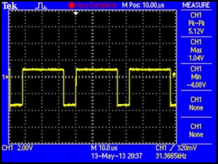
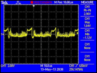
Failed seeed shield, with PWM signal measured at pin (left) and track voltage (right)
Wrapup
I’m not too happy about the way the Seeed shield died. I’d planned to use that model because it has a pin selection that is compatible with their relay shield. The Ardumoto may work with the Seeed relay shield (I need to look into that in more detail), but I am considering getting a DFRobot motor shield, which won’t, and that could cause me to go look for another relay shield.
I expect this adventure is far from done yet. Although I do want to start getting into actually using the sensors and some relays to control a train, given past experience, I likely have a number of other problems to surmount that I haven’t even discovered yet.
I’ve posted the source code for the motor library, along with the oscillate and simple_throttle example programs, on github in KensCode/TrainMotor.