JNS Forum Contest 2011
Status: September 2011 - Contest over, work incomplete
The Contest
The JNS forum folks are once again running a contest (discussed in the Summer 2011 Project Party thread). This time there’s no specific theme, beyond Japanese trains and model railroading, you just have to pick a project that can be completed in two months, plan it, and they spend July and August working on it and posting status updates. There will be a vote at the end to decided a winner. That’s about it, possibly a nominal prize, but mostly just an opportunity to drive some project to completion by talking about it every week.
I’m dithering (I’m good at dithering; everyone needs a talent). So far I’ve come up with three possible projects, but remain undecided which I’ll do:
- Complete my Urban Tram layout. This may be too much for a two-month project.
- Build the upper deck and roadway for my Expressway. This seems more achievable, and I’ve wanted to do it for some time now.
- Actually build the Riverside Commuter station I’d planned to do during last year’s contest, but never actually started. I don’t think I’m going to do this, but it’s an option.
As of late June, I’ve decided to go with #2. This seems like a manageable-size project. I’ll be working on #1 this summer also, but I suspect it’s going to be too large to have “done” by the end of the summer, and in any case I wanted to start working on it before July.
July 1: Start
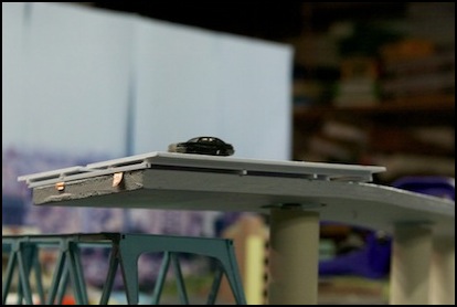
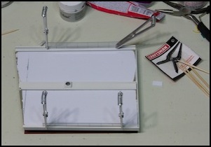
And construction formally starts. Here’s what I’m starting from: a four-foot-long strip of painted plywood held up by PVC tubes around a 1/4” threaded rod. My project is to build the roadway deck on this, along with associated details, signs, etc.
Starting position
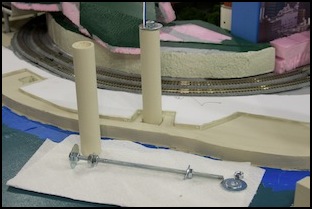
The support columns are held in place by washers, and one is drilled to allow a wire up for the lighting.
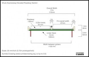
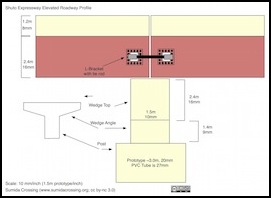
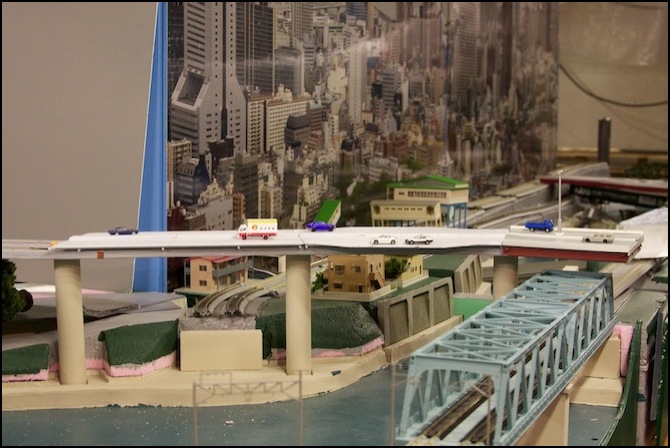
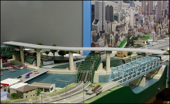
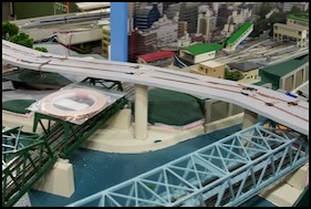
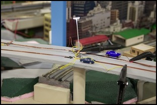
The deck, and a side view (see diagrams album for larger ver.)
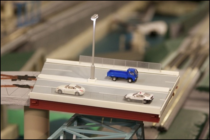
The deck will basically just be a set of segments that link together and sit atop the plywood strip, held in place by gravity. And each segment isn’t much more than some sheet styrene. The devil is going to be in the detail work, and painting, as this is going to be right in the face of anyone looking at the layout, and visible from just about every photographic angle I’d use, so it has to be one of the more detailed parts.
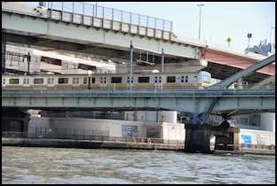

Photographers: ykanazawa1999, Ebiebi2
And the above photos give an idea of what I want it to look like.
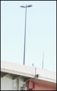
Streetlight Detail (from above photo)
First task: get the power wiring finished and hooked up, so I’ll be able to test out the lights as I get them installed.
July 10: Power Wiring and Test
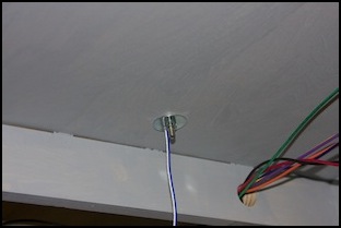
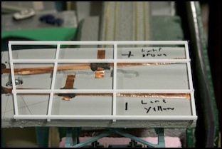
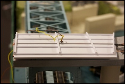
The first week’s project was to get the power for the eventual street lights atop the expressway wired up. I’m using one of my existing 12V DC lighting supplies (driven off a regulated 12V wall-wart, similar to this one but I use a 1.5Amp (1500 mA) model I found locally). Wires run to terminal strips on the underside of each table, and I just needed to connect to that, and bring the power up to the deck.
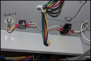
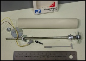
The left photo above shows the connection to the power bus (terminal strip on right), while the right photo shows the support post with its washers drilled to allow the wires to run up to the top. Also in the right photo is the Viessmann HO-scale streetlight I’m using. The left photo below shows how the wires come up to a socket; the matching plug has yet to be installed in this photo, but now has been. The plug/socket arrangement allows the deck to be removed without disturbing the support posts or wires, so work can be performed on it on the workbench.
The Viessmann lights also use a socket system, so the light poles can be removed when working on scenery. They even include a small plug (black cone in photo above) that snaps into the socket to protect it from paint or scenic materials when the lamp is removed.
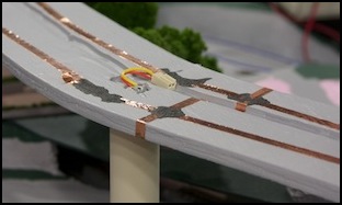
As you can see in the two photos above, 1/4” copper tape was run along the plywood to provide a power bus. Eventually the styrene expressway deck will sit above this, and make contact with the copper to provide power to the streetlights. Although not strictly necessary, where two strips touch I’ve reinforced the tapes own adhesive (which is conductive) with a dab of black “Wire Glue” (a water-based graphite glue that conducts electricity). The result had just 0.5 ohms of resistance along the 4-foot length of the expressway, with several tape-to-tape connections, far too low to be of concern. I’ve written up some earlier testing of this tape/glue combination of solder-free wiring separately. However, in this instance I actually did use solder to attach the plug assembly (not shown) to the copper tape, as I was afraid it would be under sufficient mechanical stress over time that the glue might fail (although my earlier tape/glue test rig has been kicking around on my workbench for a number of weeks, getting bumped repeatedly, and the wires glued to the copper tape with wire glue are still attached, even after the tape has started to peel away from the styrene, so it is a pretty solid bond.
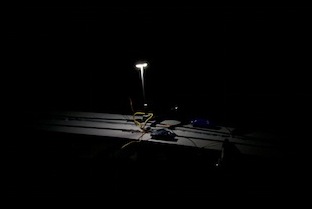
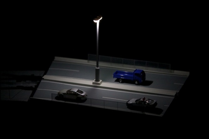
These two photos show the first test of the lighting. Although these LED-based lights are rated for 14-16 V DC, as expected they work find on 12V DC also. They throw a fairly bright light in roughly a four-inch circle, which is a nice match for my planned 8” spacing between lights. The color is a very white 5000°K, which will look slightly bluish; a reasonable color for an expressway, although a more yellowish color (which would look more like a Sodium arc light) might be preferable.
I’ve added larger versions of the above photos to the Highway Photos album.
So, a successful week. Now I need to get the first deck assembly together for week 2, and work out some remaining size/clearance issues. I may also experiment with painting the first deck assembly, depending on how things go.
July 17: Deck Prototype
Now it’s time to start building the deck itself. First I’m going to make a “prototype”, in the sense of a trial version, not a 1000mm to the meter prototype expressway! That wouldn’t quite fit in the basement.
To do this I started by making a pattern using a sheet of thin cardboard (cut from a cereal box) and used it to plan the spacing of the support frame. That’s a change from earlier plans, since I realized the deck needed to sit higher to clear the wiring from the lamp pole and to provide a way to make contacts for the power feeds.
The sheet styrene was cut using a scribing tool. And about 30 passes were needed to get 2mm styrene thin enough to snap; I'm considering investing in a model-sized table saw due to the amount of cutting needed on this project (and the expectation that it will be useful for future projects).
Following that I built a median strip. It differs from the diagram slightly, being assembled from some 0.040" (1mm) square stock to lift it up, and with two strips of 0.080" (2mm) square stock flanking a section of 0.080"x0.250" (6.3mm) strip to form the top, which was needed as I realized the median had to be wider than originally planned to permit the lamp socket to be mounted.
Finally, I cut two roadway surface elements from 0.030" (0.75mm) sheet stock. This notches under the edge of the median (and also under the edge of the not yet build side railing structures) to form a removable roadway surface that can be painted separately from the expressway deck itself.
In test-fitting the roadway I discovered that despite working from the same pattern, I'd cut them at a slightly different angle than the underlying support (not quite sure how I managed that). Some work on the frame with a file removed the bit that stuck out (I don't care if they're an exact match, as long as the top overhands the support slightly and not the other way around).
After this the roadway parts were cleaned (soap and water) and painted with several coats of what I thought was a white primer, which turned out to be a beige, and then re-painted with "matt white" model paint, which turned out to be a lighter beige (I swear, nobody seems able to make a white, "white").
July 23: Deck Prototype II
Work on the initial segment continued this week, with creation of the sidewalls and “support beams” (which mostly hide the plywood when viewed edge on), installation and wiring of the lamp-pole socket, and painting. In fact, rather a lot of painting.
The deck assembly itself still lacks the center guardrail, but it has now been painted and is taking on its final appearance. The sidewalls, median and other exposed “concrete” parts were first painted concrete. That came out too dark for sun-bleached concrete, so instead I used the “matt white” I’d first put on the roadways for “white” stripes. Painted over an underlayer of the darker color, this resulted in a reasonable-looking color, although it took the remainder of the can of white paint (it doesn’t cover a dark color well without a half-dozen or more coats), and it still a bit too light (and photographs make it seem whiter).
Dark “concrete” color sidewalls and median
Then I added the stripes and roadway color, by applying 1/16” art tape over the “matt white” I’d painted the roadway sections last week. This is a low-tack “crepe” tape that can be easily removed and serves well for masking narrow lines. The 1/16” size was the narrowest I could find at my local store, and about twice the width I wanted (it equates to a scale 24cm or 9+ inches). However, the end result doesn’t look too bad. After spraying, I let the paint dry for several hours, until it was dry to the touch but not fully cured, then I carefully pulled up each section of tape (pulling at a 180° angle to minimize “lift” on the paint coating the tape) and left the roadways to dry.
(I forgot to take any photos of the stripe painting; see below for the finished look)
BTW, on the prototype the length and gaps of the dashed centerline vary, but (measured using Google Earth) 4.3m long stripes separated by 5.8m long gaps are typical. This equates to 29mm stripes and 39mm gaps, and that’s roughly what I used.
Power wiring was connected to some pickups made from copper foil tape using Wire Glue, and once dry this was covered with a layer of super-glue to strengthen it. After that, the protective fencing above the tracks was installed. The fencing is a Casco Pipe Fence, which is transparent plastic printed with the fence pattern that needs to be cut out. I scraped some paint off the side walls and used a small drop of styrene cement at each end to attach it.
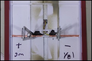
Gluing power pickups (left) and railings (right)
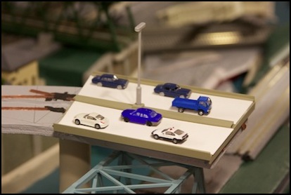
Finally, after building the two underside girders I painted these, and then glued them to the assembled deck. The cylinders on each end are a feature of some, but not all, roadway segments on elevated highways in Tokyo. I suspect these are spring-loaded linkages (there’s a rod between adjacent cylinders) to absorb lateral forces during an earthquake and keep roadway sections from falling off supports. They seem most typical above railways, roads and water, where a falling section would do the most damage.
I still haven’t made the guardrail that goes in the median.
Finished (mostly) roadway section
And with the streetlight lit at night
In all, this section has required 35 different parts so far (including the lamp assembly as one part), many of them cut by hand using the scribe-and-snap approach as they were wider than any available stock. As noted last time, I’m going to make some changes on future segments to simplify this, but I really need a good saw that can cut long, straight strips of plastic at a constant width. I’m considering a very high-grade modeler’s table saw and may put the remaining work on hold until I get one (which will probably take a couple of weeks).
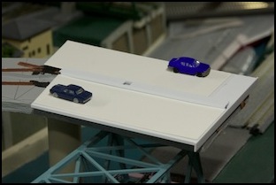
September 2011
I stopped making notes on this page as I’d switched to the new website software, and this page wasn’t initially brought over to the new system. I’d bought the new saw mentioned above, and used it to makes a couple of additional segments, but hadn’t fully completed them when the contest ended. And I promptly got distracted with several other things I’d set aside while working on the highway, so it remained as seen below for a number of months. Work will eventually resume.